Table of Contents
Advertisement
Quick Links
Advertisement
Table of Contents

Related Manuals for Lithium Grim The Senator


Summary of Contents for Lithium Grim The Senator
- Page 1 The Senator Building instructions v1.0...
-
Page 2: Table Of Contents
The Senator v1.0 Table of contents PCB layout ............................... 3 Components ............................4 Power section ............................5 Hardwire voltages ..........................5 9V only ..............................5 Build sequence ............................5 Enclosure (drilling) ..........................6 Off board wiring ............................7 Potentiometers non PCB mounted ..................... 7 Potentiometers PCB mounted ...................... -
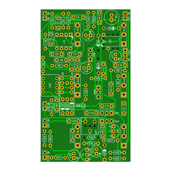
Page 3: Pcb Layout
The Senator v1.0 PCB layout Dimensions: 84 mm x 49,6 mm 3.31 inch x 1.95 inch Manufacturers and product names are mentioned solely for circuit identification, and where applicable their trademarks are the property of their respective owners who are in no way associated or affiliated with the author. No cooperation or endorsement... -
Page 4: Components
The Senator v1.0 Components Name Value Comment Name Value Comment SMF/MKT/Wima TL072 see modifications 100n SMF/MKT/Wima LT1054 120p MLCC B100k Gain 220n SMF/MKT/Wima A10k Treble 100n SMF/MKT/Wima A10k 220p MLCC A10k Bass 220n SMF/MKT/Wima B100k Level SMF/MKT/Wima C25k Boost SMF/MKT/Wima... -
Page 5: Power Section
The Senator v1.0 Power section IC2 can be either a LT1054 or a (cheaper) ICL7660S. If you want to use the 7660S then you’ll need to connect both pads of J1 I do not advise to use a battery in this build as the charge pumps will do strange things when the battery is depleted. -
Page 6: Enclosure (Drilling)
The Senator v1.0 Enclosure (drilling) I suggest you now drill the holes in your enclosure so you can use it during the off board wiring. Here is a suggestion for drilling: Pots need a 7 mm hole and switches (Caps, Push, Variac) need 6 mm holes. Diameters might differ with different brands. -
Page 7: Off Board Wiring
The Senator v1.0 Off board wiring You can either mount the potentiometers directly to the PCB with special potentiometers or use the more traditional solderlug potentiometers. Potentiometers non PCB mounted In the pictures below you see the correct pin numbering of the pots (Alpha 16mm style). -
Page 8: Switches
The Senator v1.0 Switches The PCB was designed so that 3 single pole switches will fit easily in the enclosure. There is a special gap made in the PCB which will fit almost all types of miniature single pole switches. There are a lot of configurations possible, and you are free to experiment. - Page 9 The Senator v1.0 R led1 R led2 Sleeve Sleeve Output Ring Input Note that R led1 and R led2 are 4k7 resistors. You can change these values depending on the type of LED you use but 4k7 is safe enough for almost all LEDs @9V.
-
Page 10: Modifications
The Senator v1.0 Modifications Transistors Q1 is based on the BS170P as used in a lot of Zvex™ pedals. You could use the regular BS170 instead of BS170P but note that the pinout is different (reversed)! Op amp You could use a OPA2134 instead of the TL072. Actually you can use almost any dual opamp as long as the pinout is similar to the TL072 and can handle up to +18V. -
Page 11: Pots
The Senator v1.0 Pots C25k PCB mounted pots are very hard to find. You could use a regular C25k alpha pot and mount it to the PCB with some spare leads like this: Troubleshooting All PCB’s have been 100% factory e-tested and out of every batch I receive I build an effect to double check, so there should not be a connection problem on the PCB itself. -
Page 12: Schematic
The Senator v1.0 Schematic Manufacturers and product names are mentioned solely for circuit identification, and where applicable their trademarks are the property of their respective owners who are in no way associated or affiliated with the author. No cooperation or endorsement...
Need help?
Do you have a question about the The Senator and is the answer not in the manual?
Questions and answers