
Subscribe to Our Youtube Channel
Related Manuals for ZKTeco Notus


Summary of Contents for ZKTeco Notus
- Page 1 Quick Start Guide Notus Date: June 2021 Version: 1.2 Due to regular upgrades of systems and products, ZKTeco could not guarantee exact consistency between the actual product and the written information in this manual.
-
Page 2: Installation Environment
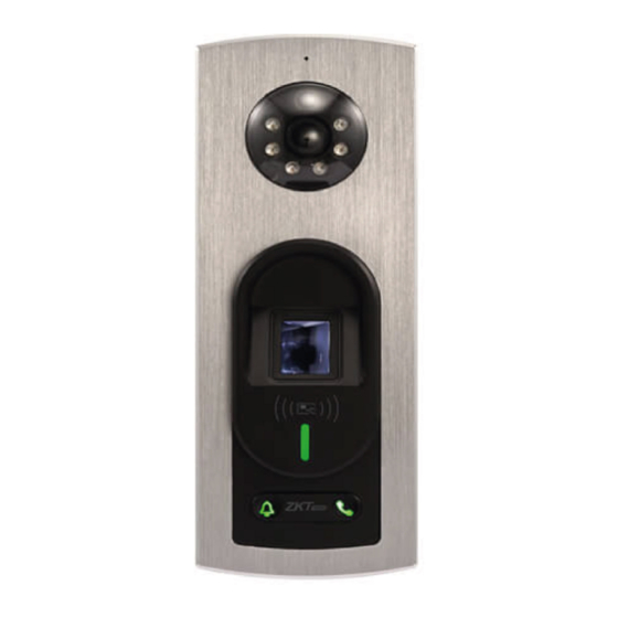
Overview Microphone Light Sensitive Diode Reset Camera Button Speaker Fingerprint Sensor Card Reading Area Indicator Call Key Doorbell Button Auxiliary Input Wiegand Out BELL- Doorbell 485B BELL+ RS485 Sensor 485A Exit Button 12V-Out Lock INWD0 Wiegand In INWD1 Alarm +12V Power In Installation Environment This product is suitable for semi-outdoor environment. -
Page 3: Device Installation
Device Installation ① 1.2m ② Attach the mounting template sticker to the wall, and drill holes ① according to the mounting paper. Fix the back plate on the wall using the wall mounting screws. Attach the device to the back plate. ②... -
Page 4: Lock Relay Connection
Door Sensor, Exit Button & Alarm Connection Detector Power BELL- Smoke Detector BELL+ Door Sensor Exit Button Alarm Alarm Power Lock Relay Connection The system supports Normally Opened Lock and Normally Closed Lock. The NO LOCK (normally opened at power on) is connected with 'NO1' and 'COM' terminals, and the NC LOCK (normally closed at power on) is connected with 'NC1' and 'COM' terminals. - Page 5 RS485 Connection 485- RS485 485B 485+ 485A Reader Wiegand Reader & Power Connection Access Controller 485B 485A +12V INWD0 INWD1 Wiegand Reader +12V 12V 3A DC Recommended ower supply is 12V - 3A To share the power with other devices, use a power supply with higher current ratings.
- Page 6 DIP Switch Connection (1) To prevent the interference, the last component in the RS485 bus is a 120 Euro resistor. That is turn the switch ‘6’ (terminal resistor switch) to ‘ON’ . (2) The RS485 terminal no. is shown in the PC software. You can change it as follows.
-
Page 7: Ethernet Connection
Ethernet Connection Network interface ZKBioAccess Note: In LAN, IP addresses of the server (PC) and the device must be in the same network segment when connecting to ZKBioAccess software. -
Page 8: User Registration
User Registration Register on ZKBioAccess software 1. Click [Access] > [Access Device] > [Device] > [Search Device] to add the device to the software. The device can be added automatically once the server address and port have been con gured on the computer. 2. - Page 9 Connect to ZSmart Users can use the ZSmart App for video intercom. Connect to ZSmart App After downloading and installing the Z Smart App on the phone, open it and add the device by scanning the QR code on the back cover of the device or scan the Video Intercom QR Code in [Device]>...
-
Page 10: Web Server
Video Door Phone Connection Visitors press the on the device to make a call and the phone will ring. The user can accept or decline the call. After the user accepts the call, it will open the video door phone interface. Webserver The user can enter the web application to set the relevant parameters of the device. - Page 11 Enter the Username and Password. Username: admin (default) Password: admin@123 (default) The Password must be changed when logging in for the rst time. Comm & Wi-Fi & Cloud Settings Click [Device]>[Comm Settings] to set the network parameters.
- Page 12 Click [Device]>[Cloud Server Settings] to set the server address and server port, that is, the IP address and port number of the server after the software is installed. For more details, please refer the Notus User Manual.
- Page 13 ZKTeco Industrial Park, No. 32, Industrial Road, Tangxia Town, Dongguan, China. Phone : +86 769 - 82109991 : +86 755 - 89602394 www.zkteco.com Copyright © 2021 ZKTECO CO., LTD. All Rights Reserved.
Need help?
Do you have a question about the Notus and is the answer not in the manual?
Questions and answers