Advertisement
Advertisement
Table of Contents

Related Manuals for ZKTeco BioPro SA20


Summary of Contents for ZKTeco BioPro SA20
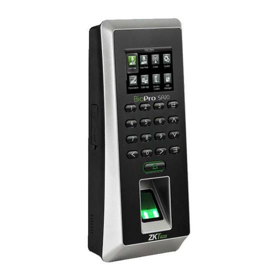
- Page 1 QUICK START GUIDE 2.4 Inch TFT Terminal Time Attendance & Access Control...
-
Page 2: Safety Precautions
Safety Precautions The following precautions are to keep user safe and prevent any damage. Please read carefully before installation. Do not install the device in a place subject to direct sun light, humidity, dust or soot. Do not place a magnet near the product. Magnetic objects such as magnet, CRT, TV, monitor or speaker may damage the device. -
Page 3: Product Pin Diagram
Product PIN Diagram 2.4-Inch TFT LCD USB Storage Device Port Keypad Reset Button Doorbell & LED Indicator Fingerprint Sensor & Card Reader Speaker Security Screw holes (for securing the device onto the back plate) - Page 4 Product PIN Diagram RS485 8 pin Cable connectors RS232 Wiegand Out 4 pin Cable connectors Ethernet (TCP/IP) Beep, LED 7 pin Cable connectors Wiegand In Power Out 485B 485A 2 pin Cable connectors Power In Alarm Lock 12pin Cable connectors Exit Button Door Sensor Doorbell...
-
Page 5: Product Dimensions & Installation
Product Dimensions & Installation Product Dimensions 7.34in 8.07in (186.5mm) (205mm) 1.78in 3.39in 3.0in (45.1mm) (86mm) (76.1mm) Mounting the device onto the wall Fix the back plate onto the wall using wall mounting screws Note: We recommend drilling the mounting plate screws into solid wood (i.e. -
Page 6: Power Connection
Power Connection Without UPS 485B 485A 12V DC 12V DC Adaptor With UPS (Optional) 485B 485A 12V DC 12V DC Adaptor Recommended power supply 12V ± 10%, at least 500mA. To share the power with other devices, use a power supply with higher current ratings... -
Page 7: Ethernet Connection
Ethernet Connection LAN Connection 485B 485A Network Cable Adaptor Ethernet Cable PIN DESCRIPTION WIRE 1 RJ45-6 Black Software 2 RJ45-3 3 RJ45-2 Green Yellow 4 RJ45-1 Note: The device can be connected to PC directly by ethernet cable. - Page 8 RS485 Connection PC Connection 485B 485A PIN DESCRIPTION WIRE 485B Yellow 485A Blue 3 GND Black Purple Gray 6 GND Black White Green Do not use Important Notes: RS485 communication wires should be a shielded and twisted pair of cable. RS485 communication wires should be connected in a bus cascade instead of a star form, to achieve a better shielding e ect by reducing signal re ec- tion during communications.
- Page 9 RS485 Connection FR1200 Connection PIN DESCRIPTION WIRE PIN DESCRIPTION WIRE BEEP Brown 485B Yellow GLED Gray 485A Blue RLED Blue 3 GND Black IWD1 Green Purple Do not use IWD0 White Gray Black 6 GND Black +12V White Green 485B 485A FR1200...
- Page 10 RS485 Settings System Settings for FR1200 Connection Select > Comm Select > Serial Comm Select > RS232/485 Change > RS485 to (master unit) DIP Settings There are six DIP switches on the back of FR1200, switches 1-4 are for RS485 address, switch 5 is reserved, switch 6 is for reducing noise on long RS485 cable.
-
Page 11: Lock Relay Connection
Lock Relay Connection Device Does Not Share Power With The Lock COM1 12V DC 485B 485A 12V DC Adaptor PIN DESCRIPTION WIRE Sensor 1 AL+ Black 2 AL- 3 NC1 Gray 4 COM1 Black 5 NO1 White 6 BUT Blue 7 GND FR107 8 SEN... - Page 12 Lock Relay Connection Device Shares Power With The Lock COM1 485B 485A 12V DC PIN DESCRIPTION WIRE 1 AL+ 2 AL- Black 3 NC1 Gray 4 COM1 Black 5 NO1 White 6 BUT Blue Sensor 7 GND 8 SEN Yellow 9 BELL+ Orange 10 BELL-...
-
Page 13: Wiegand Output Connection
Wiegand Output Connection 485B 485A PIN DESCRIPTION WIRE 485B Yellow 485A Blue 3 GND Black Purple Gray 6 GND Black White Green Do not use... -
Page 14: Standalone Installation
Standalone Installation Software Software RS232/485 RS485 Ethernet Converter ALARM Sensor No Touch EXIT Lock Exit Button Doorbell... -
Page 15: Device Operations
Device Operations Date / Time Settings Press M/OK > System > Date Time to enter Date Time setting interface. Adding User Press M/OK > User Mgt. > New User to enter the adding New User interface. Settings include inputting user ID , choosing user role (Super Admin / Normal User), registering ngerprint / badge number / password, taking user photo, and setting access control role. - Page 16 Device Operations & Troubleshooting Access Control Settings Press M/OK > Access Control to enter the Access Control setting interface. To gain access, the registered user must meet the following conditions: 1. User's access time falls within either user's personal time zone or group time zone. 2.
Need help?
Do you have a question about the BioPro SA20 and is the answer not in the manual?
Questions and answers