Advertisement
Quick Links
InBio160 Installation and Connection Guide
1.Cautions
Please note the following cautions. Mis-operation may lead to personal injury or
equipment failure:
1)Do not energize the system before installation is complete; never carry out
installation activities when the system is energized.
2)All peripheral devices must be grounded.
3)The conduits of wires under relay must be matched with metaled conduits, other wires
can use PVC conduits.
4)It is strongly recommended that the length of exposed part of any connection cable
should not be longer than 4 mm. Professional clamping tools may be used to avoid
unintentional contact of exposed wires to avoid short-circuit or communication failure.
5)It is recommended that card readers and buttons be installed at height of 1.4m-1.5m
above ground.
6)It is recommended to use the power supply for control panel, and external power
supply for each lock.
7)The appliance shall be installed and wired in accordance with national electrical
code and by qualified personnel only
Description of normal working state:
Connect the system to the power supply. If the system works properly, the POWER
indicator (red) is lit constantly and the RUN indicator (green) flashes.
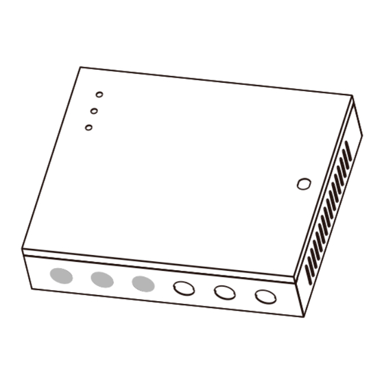
2.Components
State Indicator
Box Lock Hole
Heat
Dissipation Hole
Thread Hole
Panel Box Appearance
Version: 1.3 Date: Nov., 2015
Valve regulated lead-acid battery:
Constant voltage charge voltage regulation
Cycle use : 14.5V~14.9V(25)
Initial current: less than 2.88A
Standby use: 13.6V~13.8V(25)
Capacity: 12V, 7.2Ah/20hr
Battery Type: LC-RA127R2T1
Caution:
Do not charge in a gas tight container.
Do not short the battery terminals.
Do not incinerate
Flush with water at once if contact is made with
electrolyte (Acid)
Do not attempt to disassemble the battery.
Backup Battery
Control Panel
Temper Switch
Air Switch
Panel Track
Power Supply
Get the Panel off the track
Panel Box Insaid
3.Installation
After the following installation, fix the panel to the track first, and then install other components .
Thread holes
1) Get through the thread hole
4.LED Indicators and Wire Illustration
1) Meaning of LED indicators:
LINK indicator (green): Constant light always indicates TCP/IP communication is normal.
ACT indicator (yellow): Flashing indicates data is transmitting through TCP/IP communication.
EXT RS485 indicator (yellow&green): Flashing indicates it is sending or receiving data through RS485 communication.
PC RS485 indicator (yellow&green): Flashing indicates it is sending or receiving data through RS485 communication.
POWER indicator (red): Light always indicates the control panel is power on.
RUN indicator (green): Flashing indicates that system is working normally.
CARD indicator (yellow): Flashing indicates a card is punched on reader.
2) Recommended use of wires:
Interface
Power (A)
Wiegand (B)
Control Panel
Electric Lock (C)
1
Button (D)
EXT485 (E)
2
3) The auxiliary input may be connected to infrared body detectors, alarm switches, etc.
4 The auxiliary output may be connected to door bells, alarms, etc.
)
5) State Indicators are connected to the panel box, that is power indicator, run status indicator and communication status indicator.
1
Screws
2) Fix the box
Wire Specification
Network cable
Maximum length
18AWG*2PIN
/
1.5M
24AWG*6PIN
CAT-5 or above network cable, one
(6PIN, 8PIN, 10PIN for different
way DC impedance is less than 100Ω
100M
readers)
/KM
18AWG*2PIN+24AWG*2PIN,
18AWG*2PIN for lock connection,
/
50M
24AWG*2PIN
for
door
sensor
connection.
24AWG*2PIN
/
100M
CAT-5 or above network cable, one
20AWG*2PIN+24AWG*2PIN,
Share power with control panel: 100M
way DC impedance less than 100 Ω
20AWG*2PIN
for
reader
power
Use
independence
/KM. In wire connection, +12V and
supply, 24AWG*2PIN for RS485
(connect RS485 signal interface only):
GND of power supply need to be
communication
1000M
parallel and use double wires.
Control Panel
1
Panel Track
2
3) Install other components
power
supply
2
Advertisement

Related Manuals for ZKTeco InBio160


Summary of Contents for ZKTeco InBio160
- Page 1 3.Installation InBio160 Installation and Connection Guide After the following installation, fix the panel to the track first, and then install other components . Version: 1.3 Date: Nov., 2015 Screws Control Panel 1.Cautions Please note the following cautions. Mis-operation may lead to personal injury or...
- Page 2 5.DIP Switch Settings AUX Output 1 connect to alarm, door bell and so on; AUX Input 1 connect to the infrared human 1) Switches1-6 are used to set the control panel number in RS485 communication: It is adopted binary coding and Port (NO, COM, NC) Electrical Parameters: body induction, wireless exit button, windows MAX Voltage: 36V(DC)
- Page 3 8.Equipment Communication Insert a screw driver to the rectangular hole in the four corner of the panel back, push it in until hearing the “click” sound. Then remove the case from the panel. The following is “ we t m ode” lock connection with external power supply. The PC software can communicate with the panel according to the communication protocols (RS485 and TCP/IP) for data exchange and remote management.
Need help?
Do you have a question about the InBio160 and is the answer not in the manual?
Questions and answers