Cadel LORD 7 Installer Manual
Hide thumbs
Also See for LORD 7:
- User manual (48 pages) ,
- Installer manual (40 pages) ,
- User manual (44 pages)
Table of Contents
Advertisement
Quick Links
INSTALLER MANUAL
Pellet Stove
EN
©2020 CADEL srl | All rights reserved - Tutti i diritti riservati
LORD 7/7.0 - SWEET
7/7.0 - PERLA
7/7.0, - CRISTAL
7/7.0 -
3
3
3
ONE AIRTIGHT - BEAM AIRTIGHT - ACCENT AIRTIGHT
SHARP AIRTIGHT - LEE AIRTIGHT - SOUND
5/7 UP
3
CHROME 5/7 AIRTIGHT - ROUND 5/7 AIRTIGHT - FLOYD 5.0/7.0
Advertisement
Table of Contents

Subscribe to Our Youtube Channel
Related Manuals for Cadel LORD 7


Summary of Contents for Cadel LORD 7
- Page 1 INSTALLER MANUAL Pellet Stove ©2020 CADEL srl | All rights reserved - Tutti i diritti riservati LORD 7/7.0 - SWEET 7/7.0 - PERLA 7/7.0, - CRISTAL 7/7.0 - ONE AIRTIGHT - BEAM AIRTIGHT - ACCENT AIRTIGHT SHARP AIRTIGHT - LEE AIRTIGHT - SOUND 5/7 UP CHROME 5/7 AIRTIGHT - ROUND 5/7 AIRTIGHT - FLOYD 5.0/7.0...
-
Page 2: Table Of Contents
7.0 - ONE AT - BEAM AT - ACCENT AT - ACCENT K AT) ....19 5.7 REMOVAL/ASSEMBLY OF SIDE PANELS (CRISTAL - LORD 7.0) ...............19 5.8 REMOVAL/ASSEMBLY OF SIDE PANELS (SHARP AT - LEE AT) ................20 REMOVAL/ASSEMBLY OF BACK PANELS (PERLA 7.0) -
Page 3: Manual Simbology
MANUAL SIMBOLOGY USER AUTHORISED TECHNICIAN (ONLY to interpret or the Stove-manufacturer or the Authorized Techni- cian of Technical Assistance Service approved by the Stove-manufacturer) SPECIALIZED STOVE-REPAIRER CAUTION: READ CAREFULLY THE NOTE CAUTION: DANGER OR IRREVERSIBLE DAMAGE POSSIBILITY • The icons with the stylized figures indicates whom the subject dealt in the paragraph is addressed to (between the User and/ or the Authorized Technician and/or the Specialized Stove-repairer). -
Page 4: Stove Handling
STOVE HANDLING Both whether the stove is packed or not it is necessary to observe the following instructions for handling and transporting the stove from its sale point to its installation point and for any future movements: • The stove must be handled with idoneous means paying attention to the existing safety regulations; •... -
Page 5: Technical Features
TECHNICAL FEATURES Fig. 3 - Inclined roof LEGEND Fig. 3 Height over the ridge of the roof = 0,5 mt Roof inclination ≥ 10° 90° Measured distance at 90° from the roof surface = 1,3 mt • The chimney flue must be sealed from fumes. •... -
Page 6: Height-Depression
Fig. 4 - Example of label HEIGHT-DEPRESSION The depression (draught) of a chimney flue depends also on its height. Check the depression with the values provided at FEATU- RES a pag. 33. Minimum height 3,5 meters. MAINTENANCE • The fumes extraction pipes (fumes conduit + chimney flue + chimney pot) must always be cleaned, scrubbed and checked by an expert stove-repairer, in compliance with current regulations, with the instructions of the stove-manufacturer and the directives of your insurance company. -
Page 7: Chimney Components
CHIMNEY COMPONENTS Fig. 6 - Chimney components LEGEND Fig. 6 Chimney pot Fume outlet Chimney flue Termal insulation External wall Chimney union Fume pipe Heat generator Inspection door T-union with inspection plug CHIMNEY FLUE CONNECTION Your pellet stove works through a fume draught forced by a fan. It is obligatory to check that all pipes are realized in compliance with the following regulation on material selection: EN 1856-1, EN 1856-2 e UNI/TS 11278. -
Page 8: Examples Of Correct Installation
SYSTEM TYPE Ø80 mm PIPE Ø100 mm PIPE Minimum vertical length 1,5 mt 2 mt Maximum length (with 1 union) 6,5 mt 10 mt Maximum length (with 3 unions) 4,5 mt 8 mt Maximum number of unions Level section (minimum inclination 3%) 2 mt 2 mt Installation at a height above 1200 m a.s.l. - Page 9 Fig. 8 - Example 2 LEGEND Fig. 8 Insulating material Inspection plug Chimney inspection entrance Minimum safety distance = 0,5 mt Inclination ≥ 3° Level section ≤ 1 mt • Old chimney flue with an inserted pipe of minimum Ø100/120 mm and with an external door which enables the chimney cleaning.
-
Page 10: Combustion Air
We recommend to check with your chimney flue manufacturer the safety distances which must be respected and the type of insulating material. The aforesaid regulations are valid also for holes made on the wall (EN 13501 - EN 13063 - EN 1856 - EN 1806 - EN 15827). COMBUSTION AIR EXTERNAL AIR INLET Fig. -
Page 11: Combustible Air Inlet For Sealed-Chamber
COMBUSTIBLE AIR INLET FOR SEALED-CHAMBER INSTALLATION Fig. 11 - Air inlet for sealed-chamber installation LEGEND Fig. 11 ≥ 1,5 mt ≥ 0,3 mt Sectional view Shield grid Curve inlet to turn downwards Check if the purchased stove has a sealed-chamber. If the stove is endowed with a sealed-chamber and you want also the whole installation with sealed chamber, please read the following instructions: •... -
Page 12: Combustible Air Inlet For Sealed-Chamber
COMBUSTIBLE AIR INLET FOR SEALED-CHAMBER INSTALLATION How to connect to the stove in the sealed chamber with concentric system: Fig. 12 - Phase1 • Connect the air intake pipe to the combustion air pipe of the stove and tighten everything with a clamp (see [Fig. 12). INSTALLATION INTRODUCTION •... -
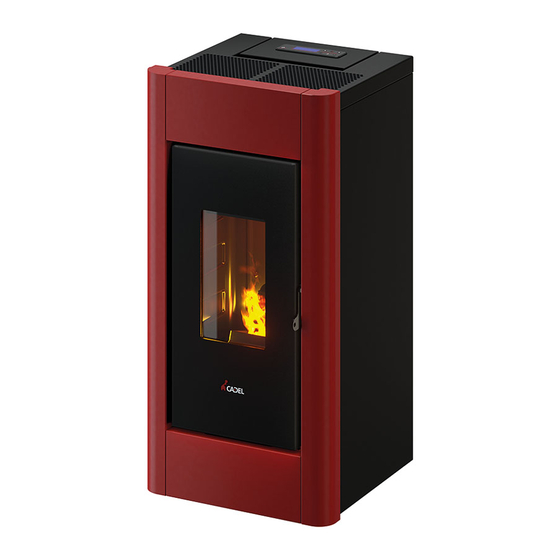
Page 13: Overall Dimensions
OVERALL DIMENSIONS Fig. 13 - General dimensions: LORD 7 - 7.0 LEGEND Fig. 13 90,7 cm 45,2 cm 45,7 cm 18,2 cm 31,4 cm 12,9 cm 20,2 cm Exhaust fumes d.8 cm Hole combustion air inlet d.6 cm Fig. 14 - General dimensions: SWEET 7 - 7.0... - Page 14 Fig. 15 - General dimensions: PERLA 7 - 7.0 LEGEND Fig. 15 94 cm 52,1 cm 45,6 cm 21,3 cm 32,4 cm 16,5 cm 20,5 cm Exhaust fumes d.8 cm Hole combustion air inlet d.6 cm Fig. 16 - General dimensions: CRISTAL 7 - 7.0 LEGEND Fig.
- Page 15 Fig. 17 - General dimensions: SHARP AIRTIGHT - LEE AIRTIGHT LEGENDE Fig. 17 Exhaust fumes d.8 cm Hole combustion air inlet d.6 cm Fig. 18 - General dimensions: SOUND3 5UP - 7UP LEGENDE Fig. 18 Exhaust fumes d.8 cm Hole combustion air inlet d.6 cm STUFE A PELLET...
- Page 16 Fig. 19 - General dimensions: CHROME 5-7 AIRTIGHT - ROUND 5-7 AIRTIGHT LEGEND Fig. 19 Exhaust fumes d.8 cm Hole combustion air inlet d.6 cm Fig. 20 - General dimensions: FLOYD 5.0 - 7.0 LEGEND Fig. 20 Exhaust fumes d.8 cm Hole combustion air inlet d.6 cm STUFE A PELLET...
- Page 17 Fig. 21 - General dimensions: ONE/BEAM AIRTIGHT LEGEND Fig. 21 95,2 cm 46 cm 45,2 cm 18,9 cm 31,4 cm 13,6 cm 20,2 cm Exhaust fumes d.8 cm Hole combustion air inlet d.6 cm Fig. 22 - General dimensions: ACCENT AIRTIGHT LEGEND Fig.
-
Page 18: General Installation
GENERAL INSTALLATION Fig. 23 - General installation LEGEND Fig. 23 Stove Minimum lateral distance = 300 mm Minimum rear distance = 200 mm Minimum front distance = 1000 mm • It is obligatory to install the stove away from walls and/or pieces of furniture, with a minimum air flow of 300 mm on the sides and 200 mm on the back, to enable an eficient appliance cooling and a good distribution of heat in the room (see Fig. -
Page 19: Removal/Assembly Of The Frame
Fig. 30 - Release the side panels Fig. 31 - Fastening teeth REMOVAL/ASSEMBLY OF SIDE PANELS (CRISTAL 7.0 - LORD 7.0) To disassemble the side panels, proceed as follows: • Undo the front screws (see Fig. 32). • Open the side panel (see Fig. 33) and release the rear teeth (see Fig. 34). -
Page 20: Lee At)
Fig. 32 - Remove the screws Fig. 33 - Rotate the side panels Fig. 34 - Remove the side panels REMOVAL/ASSEMBLY OF SIDE PANELS (SHARP AT - LEE AT) To disassemble the side panels, proceed as follows: • Unscrew the black rear profile (see Fig. 35) •... -
Page 21: Tiles Assembly (Perla 7.0)
Fig. 38 - Remove the screws Fig. 39 - Remove the side panels 5.10 TILES ASSEMBLY (PERLA 7.0) To disassemble the tiles, proceed as follows: • Place the tiles on a worktop and set the tile support above it. • Have the holes of the profile match those of the tiles and apply all the screws (see Fig. 40). •... -
Page 22: Mounting The Stand (Accent At)
Fig. 41 - Remove the screws Fig. 42 - Remove the profile 5.12 MOUNTING THE STAND (ACCENT AT) • Proceed as follows to disassemble the stand: • Lay the stove down on the ground. • Remove the stove’s feet. • Secure the stand with the screws supplied (see Fig. 43). Fig. -
Page 23: Installation Of Tee Fitting
5.14 INSTALLATION OF TEE FITTING (EXCLUDING SOUND UP - CHROME AT - FLOYD MODELS) For stoves with top exhaust, a tee fitting with inspection cap must be installed. The tee fitting must be blocked with the supplied clamp (see Fig. 46 Fig. 47) Fig. -
Page 24: 5.17 Electric Connection
• When the stove is not going to be used for a long period of time, it advisable to remove the plug from the socket on the wall. 5.18 CONNECTION TO THE EXTERNAL THERMOSTAT ( LORD 7.0 - FLOYD 5.0, 7.0 ) The stove works through a thermostat probe placed in its inner. -
Page 25: Connection To The External Thermostat
• Scroll with the P3 key up to: Pr46 Enable Remote "Pr46 rEMoto EnAbLEd ". • Press the P1 or P2 key to modify the status. • Confirm with the P3 key. • Scroll to MB Output "Mb EScAPE " with key P1 or P2. •... -
Page 26: Special Maintenance
NB: for good combustion, the depression values must be between + -5 Pa and the temperature values between + - 10°C. SPECIAL MAINTENANCE INTRODUCTION For a long working life of the stove, have a periodic cleaning of the stove as described in the following paragrafs. •... -
Page 27: Fume Passages Cleaning
• Extract the ash which has accumulated in the inner. • After cleaning repeat the operation in reverse order, checking the condition and efficiency of the gasket, and if necessary replace it. It is important to sealed the cap othrwise noxiuous fumes will propagate among the room. Fig. -
Page 28: Room Fan Cleaning
Fig. 61 - Clean with pipe cleaner Fig. 62 - Vacuum out the ash • Clean with a pipe cleaner and suction any ash accumulated inside (see Fig. 61 and Fig. 62). • After cleaning, repeat the operation in reverse making sure the gasket is intact and efficient: if necessary, provide for the replacement with original spare parts. -
Page 29: Fume Pipes Annual Cleaning
• Unscrew the side screws. (see dedicated chapters). • Remove dust build-up using a brush or a vacuum cleaner (see Fig. 65). FUME PIPES ANNUAL CLEANING Clean annually from soot with brushes. The cleaning operation must be executed by a specialized stove-repairer who will provide for the cleaning of fume pipe, chimney flue and chimney pot. - Page 30 PROBLEM CAUSE SOLUTION INTERVENTION Empty hopper Full the hopper. Open fire door or Close fire door and pellet door and check that there are no open pellet door pellet grains at the gasket level. Clogged stove Fume chamber cleaning Pellets do not reach the combu- Auger blocked by a stion chamber...
- Page 31 PROBLEM CAUSE SOLUTION INTERVENTION Check as following: probable obstructions of the combusti- Not sufficient ble air inlet from the back or from the bottom of the stove; combustion air burning pot obstructed holes with too ash remains. Have the fan blades and auger cleaned. The exhaust chimney is partially or totally obsturcted.
-
Page 32: Technical Datas
PROBLEM CAUSE SOLUTION INTERVENTION Routine main- Stove running and When this flashing message appears upon start-up, it means tenance alert (it display showing that the preset operating hours have elapsed before mainte- does not block the "SERVICE" nance. Contact the service centre. system) TECHNICAL DATAS REPAIR INFORMATION... -
Page 33: Features
FEATURES DESCRIPTION LORD 7 SWEET PERLA WIDTH 45,2 cm 47 cm 52,1 cm DEPTH 45,7 cm 45,2 cm 45,6 cm HEIGHT 90,7 cm 95 cm 93,8 cm WEIGHT 55 kg 56 kg 60 - 67 kg INTRODUCED THERMIC POWER (Min/Max) - Page 34 DESCRIPTION LORD 7.0 SWEET PERLA WIDTH 45,2 cm 47 cm 52,1 cm DEPTH 45,7 cm 45,2 cm 45,6 cm HEIGHT 90,7 cm 95 cm 93,8 cm WEIGHT 55 kg 56 kg 60 - 67 kg INTRODUCED THERMIC POWER (Min/Max) 2,8 - 7,7 kW...
- Page 35 DESCRIPTION CRISTAL CRISTAL WIDTH 47,7 cm 47,7 cm DEPTH 45,4 cm 45,4 cm HEIGHT 90,7 cm 90,7 cm WEIGHT 56 kg 56 kg INTRODUCED THERMIC POWER (Min/Max) 2,8 - 7,7 kW 2,8 - 7,7 kW NOMINAL THERMIC POWER (Min/Max) 2,6 - 7 kW 2,5 - 7 kW EFICIENCY (Min/Max) 92 - 90 %...
- Page 36 LEE AT - SHARP DESCRIPTION ONE AT- BEAM AT ACCENT AT WIDTH 46 cm 46 cm 46 cm DEPTH 45,2 cm 45,2 cm 45,2 cm HEIGHT 95,2 cm 95,2 cm 98,7 cm WEIGHT 56 kg 56 kg 59 kg INTRODUCED THERMIC POWER (Min/Max) 2,8 - 7,7 kW 2,8 - 7,7 kW 2,8 - 7,7 kW...
- Page 37 CHROME 5AT - DESCRIPTION SOUND3 5 UP FLOYD 5.0 ROUND5 AT WIDTH 50 cm 50 cm 50 cm DEPTH 59 cm 59 cm 59 cm HEIGHT 95 cm 95 cm 95 cm WEIGHT 76 kg 73 kg 65 kg INTRODUCED THERMIC POWER (Min/Max) 2,8 - 6,1 kW 2,8 - 7,7 kW 2,8 - 7,7 kW...
- Page 38 CHROME/ROUND DESCRIPTION SOUND3 7 UP FLOYD 7.0 - 7AT WIDTH 50 cm 50 cm 50 cm DEPTH 59 cm 59 cm 59 cm HEIGHT 95 cm 95 cm 95 cm WEIGHT 76 kg 73 kg 65 kg INTRODUCED THERMIC POWER (Min/Max) 2,8 - 7,7 kW 2,8 - 7,7 kW 2,8 - 7,7 kW...
- Page 39 NOTE...
- Page 40 Rev. 02 - 2021 CADEL srl www.cadelsrl.com 31025 S. Lucia di Piave - TV www.free-point.it Via Foresto sud, 7 - Italy www.pegasoheating.com Tel. +39.0438.738669 Fax +39.0438.73343...
Need help?
Do you have a question about the LORD 7 and is the answer not in the manual?
Questions and answers