Table of Contents
Advertisement
Quick Links
Introduction .................................................................... 1
Key Features ................................................................. 2
Chapter 2
Installation Instructions................................................... 5
1. External Connectors .................................................. 6
PS/2 Keyboard /Mouse Connector ................................ 6
USB1, USB2 and LAN Connectors ................................. 6
Parallel Port, Serial Port Connectors ............................. 6
Line-in jack, Mic-in jack, Speaker-out jack and
MIDI/Joystick Connector ................................................. 7
6-Channel Audio ............................................................ 7
Hard Disk LED Connector ( HD_LED ) .......................... 8
Reset Switch ( RESET ) ................................................. 8
Speaker Connector ( SPEAKER ) .................................. 9
Power LED Connector( PWR_LED ) .............................. 9
Green LED Connector( GREEN_LED ) ......................... 9
ACPI LED Connector( ACPI_LED ) ................................ 9
Hardware Green Connector ( SLEEP SW ) ................... 9
Key Lock Connector( KEYLK ) ....................................... 9
COM2,USB3 ,USB4 Connector ...................................... 10
Infrared Header ( IrDA ) ................................................. 10
Intruder Detect Switch( JINTR ) ...................................... 11
Wake-Up On LAN ( WOL ) ............................................. 12
Wake-Up On Internal Modem ( WOM ) .......................... 12
Audio Connectors (CD_IN1, CD_IN2, MODEM_IN ) ....... 13
4-pin SMBus Connector( SMBUS ) ................................ 13
Diagnosis LED ............................................................... 14
Hyper-Threading Detector ............................................. 14
Audio Interface ............................................................... 15
SPDIF Connector ...........................................................16
Chassis Security Switch(CHSSEC) ................................ 16
2. Jumper Settings .................................................. ..... 17
Advertisement
Table of Contents

Related Manuals for QDI PlatiniX P8/333 Series


Summary of Contents for QDI PlatiniX P8/333 Series
-
Page 1: Table Of Contents
Chapter 1 Introduction ..............1 Key Features ..............2 Chapter 2 Installation Instructions........... 5 1. External Connectors ..........6 PS/2 Keyboard /Mouse Connector ........ 6 USB1, USB2 and LAN Connectors ......... 6 Parallel Port, Serial Port Connectors ......6 Line-in jack, Mic-in jack, Speaker-out jack and MIDI/Joystick Connector .......... - Page 2 Advanced BIOS Features Setup..........31 Advanced Chipset Features Setup........33 Power Management Setup.............35 PnP/PCI Configurations Setup..........38 Integrated Peripherals............39 PC Health Status..............42 Password Setting..............44 Boot with BIOS defaults............44 Appendix QDI Driver CD............... 45 Norton AntiVirus..............45 LogoEasyII................46 BIOS-ProtectEasy..............47 RecoveryEasyII..............48 SpeedEasyII................53 BootEasy................54 StepEasyII................55 BootEasy(German)..............57 Platinix2E/333(Spanish)............
-
Page 3: Chapter 1 Introduction
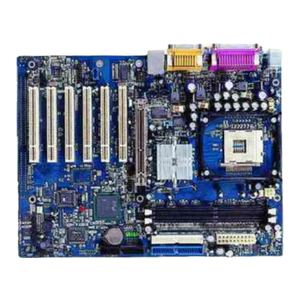
Chapter 1 Chapter 1 Chapter 1 Chapter 1 Chapter 1 Chapter 1 Introduction P8/333 series of mainboards utilize Intel ® 845GE chipset consisting of two components: the Intel 845GE Graphics Memory Controller Hub(GMCH) and the I/O Controller Hub4(ICH4), providing a fully compatible, high performance and cost-effective ATX platform. -
Page 4: Key Features
Introduction Introduction Introduction Introduction Introduction Key Features Form factor ATX form factor of 305mm x 232mm Microprocessor Supports Intel ® Pentium 4 (Hyper-Threading) socket 478 processors Supports Intel Pentium 4 (Willamette) socket 478 processors at 1.8/1.9/2.0GHz ® Supports Intel Pentium 4 (Northwood) socket 478 processors at 1.8/2.0/2.2/2.26/2.4/2.53/2.66 ®... - Page 5 Provides Diagnosis LEDs to indicate CPU, chipset, memory PCI device, clockgen and video status during system booting up Providing QDI innovations: RecoveryEasyII, BIOS-ProtectEasy, LogoEasyII, BootEasy, StepEasyII, SpeedEasyII CPU, AGP, DDR Voltage adjusting function with SpeedEasyII: Adjusting CPU, AGP and DDR core voltage in BIOS to improve system stability and overclocking ability.(optional)
- Page 6 Introduction Introduction Introduction Introduction Introduction BIOS Licensed advanced AWARD(Phoenix) BIOS, supports flash ROM, plug and play ready Supports IDE CDROM/SCSI/USB boot up. Green function Supports ACPI (Advanced Configuration and Power Interface) and ODPM (OS Directed Power Management) Supports ACPI power status: S0 (full-on), S1 (power on suspend), S3 (suspend to RAM), S4(suspend to Disk, depends on OS) and S5 (soft-off) Main Expansion Slots and Connectors Slot/Port (Quantity)
-
Page 7: Installation Instructions
Chapter 2 Chapter 2 Chapter 2 Chapter 2 Chapter 2 Chapter 2 Installation Instructions This section covers External Connectors and Jumper Settings. Refer to the mainboard layout chart for locations of all jumpers, external connectors, slots and I/O ports. Furthermore, this section lists all necessary connector pin assignments for your reference. -
Page 8: External Connectors
Installation Instr Installation Instr Installation Instr Installation Instr Installation Instruction uction uction uction uction External Connectors PS/2 Keyboard/Mouse Connector PS/2 keyboard connector is for the usage of PS/2 keyboard. If using a standard AT size keyboard, an adapter should be used to fit this connector. PS/2 mouse connector is for the usage of PS/2 mouse. -
Page 9: Midi/Joystick Connector
Chapter 2 Chapter 2 Chapter 2 Chapter 2 Chapter 2 Line-in jack, Microphone-in jack, Speaker-out jack and MIDI/Joystick Connector (Available on -A/-AL/ mainboard) The Line-in jack can be connected to devices such as a cassette or minidisc player to playback or record. -
Page 10: Atx 12V Power Supply Connectors & Power Switch
Installation Instr Installation Instr Installation Instr Installation Instr Installation Instruction uction uction uction uction ATX 12V Power Supply Connector & Power Switch (POWER SW) The power switch (POWER SW) should be connected to a momentary switch. When powering up your system, first turn on the mechanical switch of the power supply (if one is provided), then push once the power switch. -
Page 11: Speaker Connector (Speaker)
Chapter 2 Chapter 2 Chapter 2 Chapter 2 Chapter 2 Speaker Connector (SPEAKER) The connector can be connected to the speaker on the case. Power LED Connector (PWR_LED) When the system is in S0 status, the LED is on. When the system is in S1 status, the LED is blink;... -
Page 12: Com2,Usb3 ,Usb4 Connector
Installation Instr Installation Instr Installation Instr Installation Instr Installation Instruction uction uction uction uction USB3 ;USB4;Serial Port Connector(COM2) Besides USB1,2 on the back panel, P8/333 series of mainboards also have two 8-pin headers on board which may connect to front panel USB cable( optional ) to provide additional four USB ports. -
Page 13: Fan Connectors( Cpu_Fan , Sys_Fan, Pwr_Fan )
Chapter 2 Chapter 2 Chapter 2 Chapter 2 Chapter 2 Fan Connectors (PWR_FAN, CPU_FAN, SYS_FAN(optional)) The fan speed of these three fans can be detected and viewed in “PC Health” section of the CMOS SETUP. SYS_FAN +12V SENSE CPU_FAN +12V SENSE PWR_FAN +12V... -
Page 14: Wake-Up On Lan (Wol)
Installation Instr Installation Instr Installation Instr Installation Instr Installation Instruction uction uction uction uction Wake-Up On LAN (WOL) Through the Wake-Up On LAN function, a wake event occurring from the network can wake up the system. If this function is to be used, please be sure an ATX12V power supply and a LAN adapter which supports this function are used. -
Page 15: Audio Connectors (Cd_In1, Cd_In2, Modem_In )
Chapter 2 Chapter 2 Chapter 2 Chapter 2 Chapter 2 Audio Connectors (CD_IN 1, CD_IN 2(optional),MODEM_IN) (Available on -A/-6A/-AL/-6AL mainboard) CD_IN 1,and CD_IN 2 are Sony standard CD audio connectors, they both can be connected to a CD-ROM drive through a CD audio cable. The MODEM connector allows the onboard audio to interface with a voice modem card with a similar connector. -
Page 16: Diagnosis Led
Installation Instr Installation Instr Installation Instr Installation Instr Installation Instruction uction uction uction uction Diagnosis LED(optional) During the POST , the LED1~LED5 representing POST steps will light up in turn. please refer to the following table to learn the POST status: LED1 LED2 LED3 LED4 LED5 status blink... -
Page 17: Audio Interface
Chapter 2 Chapter 2 Chapter 2 Chapter 2 Chapter 2 Audio Interface(Optional) The audio interface provides three kinds of audio output choices: the FrontAudio, the RearAudio and the ActiveAudio. Their priority level is as sequence. When the FrontAudio is available, the RearAudio and the ActiveAudio( in-case speakers ) will be cut off. When the RearAudio is available, the ActiveAudio will be cut off. -
Page 18: Spdif Connector
Installation Instr Installation Instr Installation Instr Installation Instr Installation Instruction uction uction uction uction SPDIF Connector(optional) The SPDIF input allow your digital audio input from digital audio devices.(optional) The SPDIF output is capable of providing digital audio data or compressed AC3 data to an external Dolby digital decoder. -
Page 19: Jumper Settings
Chapter 2 Chapter 2 Chapter 2 Chapter 2 Chapter 2 Jumper Settings Jumpers are located on the mainboard, the clear CMOS jumper CLR_CMOS, enable key- board password power-on function jumper JKB etc. Pin 1 for all jumpers are located on the side with a thick white line (Pin1→... -
Page 20: Overclocking Jumper Setting(Jfs0,Jfs1)
For bus ratio unlocked processor, this overclocking feature can be implemented by setting FSB as 100x4/133x4/200x4MHz, meanwhile adjusting the bus ratio (multiplier) in “QDI Innovation features” in AWARD BIOS CMOS Setup and memory. You can also adjust the CPU frequency by running StepEasyII. We do not guarantee the stability of the overclocking system. -
Page 21: Bios-Protection Jumper (Bios_Wp)
Enabled Setting the jumper BIOS_WP as open(default), meanwhile disabling the “Flash Write Pro- tect” item from “QDI Innovation features ” in AWARD BIOS CMOS Setup, allows you to flash the BIOS to the Flash ROM. The DMI (Desktop Management Interface) system information such as the CPU type/speed, memory size, and expansion cards will be detected by the onboard BIOS and stored in the flash ROM. -
Page 22: Enable Keyboard Password Power-On Function(Jkb)
Installation Instr Installation Instr Installation Instr Installation Instr Installation Instruction uction uction uction uction Enable keyboard password power-on function (JKB) The mainboard provides the advanced keyboard password power-on function. Before using this function, set JKB with pin1 & pin2 closed. Otherwise, set JKB with pin2 & pin3 closed for disabling. -
Page 23: Clear Cmos(Clr_Cmos)
Chapter 2 Chapter 2 Chapter 2 Chapter 2 Chapter 2 Clear CMOS (CLR_CMOS) If you want to clear CMOS, unplug the AC power supply first, close CLR_CMOS (pin1 & pin2) once, set CLR_CMOS back to the normal status with pin2 & pin3 connected, then power on the system. - Page 24 T-- This page is intentionally left blank --his...
-
Page 25: Chapter 3 Bios Description
Chapter 3 Chapter 3 Chapter 3 Chapter 3 Chapter 3 Chapter 3 BIOS Description The mainboard uses AWARD BIOS Setup program that provides a Setup utility for users to modify the basic sys- tem configuration. The information is stored in CMOS RAM so it retains the Setup information when the power is turned off. -
Page 26: Awdflash.exe
1. Create a bootable system floppy diskette by typing Format A:/s from the DOS prompt under DOS6.xx or Windows 9x environment. 2. Copy AWDFLASH.EXE(version>=8 .22q) from the directory \Utility located on QDI Driver CD to your new bootable diskette. 3. Download the updated BIOS file from the Website (http://www.qdigrp.com). Please be sure to download the suitable BIOS file for your motherboard. -
Page 27: Award Bios Description
Chapter 3 Chapter 3 Chapter 3 Chapter 3 Chapter 3 If you require more detailed information concerning AWDFLASH Utility, for example, the different usage of parameters, please type A:\>AWDFLASH /? Because the BIOS Software will be updated constantly, the fol- Note: lowing BIOS screens and descriptions are for reference purposes only and may not reflect your BIOS screens exactly. - Page 28 BIOS Description BIOS Description BIOS Description BIOS Description BIOS Description Figure-2 Standard CMOS Setup Menu For the items marked, press enter, a window will pop up as shown below. You can view detailed information or make modifications. Figure-2-1 IDE Primary Master Setup Menu Hard Disk Primary Master/Primary Slave/Secondary Master/Secondary Slave These categories identify the HDD types of 2 IDE channels installed in the computer system.
- Page 29 Chapter 3 Chapter 3 Chapter 3 Chapter 3 Chapter 3 The Award BIOS supports 3 HDD modes: CHS, LBA and LARGE. Generic access mode in which neither the BIOS nor the IDE controller will make any transfor- mation during accessing. The maximum number of cylinders, heads and sectors for CHS mode are 1024,16 and 63.
- Page 30 BIOS Description BIOS Description BIOS Description BIOS Description BIOS Description Video Set this field to the type of video display card installed in your system. EGA/ VGA Enhanced Graphics Adapter / Video Graphic Array. For EGA, VGA, SEGA, SVGA or PGA monitor adapters. CGA 40 Color Graphic Adapter, powering up in 40 column mode.
-
Page 31: Qdi Innovation Features
Chapter 3 Chapter 3 Chapter 3 Chapter 3 Chapter 3 QDI Innovation features Figure-3 QDI Innovation features Menu The following indicates the options for each item and describes their meaning. Item Option Description [SpeedEasyII setting] CPU Clock Ratio x1~x99 Select the multiplication of processor core frequency. If a Ratio locked processor is installed, this item will be hidden. - Page 32 BIOS Description BIOS Description BIOS Description BIOS Description BIOS Description [BootEasy setting] QDI BootEasy Enabled PC boot in rapid speed, without any redunant feature feature waiting for the displaying of starting OS. Disabled PC boot in the legacy BIOS way.
-
Page 33: Advanced Bios Features Setup
Chapter 3 Chapter 3 Chapter 3 Chapter 3 Chapter 3 Advanced BIOS Features Setup Figure-4 Advanced BIOS Features Menu The following indicates the options for each item and describes their meaning. Item Option Description Virus Warning Enabled Guard against boot virus threats early in the boot cycle, before they have a chance to load into your system, ensuring your computer boots to a clean operating system. - Page 34 BIOS Description BIOS Description BIOS Description BIOS Description BIOS Description Swap Floppy Enabled If the system has two floppy drives, choose enable Drive Disabled to assign physical drive B to logical drive Aand vice- versa. Boot Up Keypad is used as number keys. NumLock Status Keypad is used as arrow keys.
-
Page 35: Advanced Chipset Features Setup
Chapter 3 Chapter 3 Chapter 3 Chapter 3 Chapter 3 Advanced Chipset Features Setup Figure-5 Advanced Chipset Features Menu The following indicates the options for each item and describes their meaning. Item Option Description DRAM Timing Manual DRAM timing is defined by user. Selectable By SPD DRAM timing is defined by SPD. - Page 36 BIOS Description BIOS Description BIOS Description BIOS Description BIOS Description System BIOS Enabled Besides conventional memory, the system BIOS area Cacheable is also cacheable. Disabled System BIOS area is not cacheable. Video BIOS Enabled Besides conventional memory, video BIOS area is Cacheable also cacheable.
-
Page 37: Power Management Setup
Chapter 3 Chapter 3 Chapter 3 Chapter 3 Chapter 3 Power Management Setup Figure-6 Power Management Setup Menu The following indicates the options for each item and describes their meaning. Item Option Description ACPI function Enabled Enable ACPI function. ACPI Suspend S1(POS) Select the ACPI suspend type. - Page 38 BIOS Description BIOS Description BIOS Description BIOS Description BIOS Description Video Off In The system will disable video when entering suspend Suspend mode. Do not turn off video when entering suspend mode. Suspend Type Stop Grant Select the Suspend type. PwrOn Suspend MODEM Use 3,4,5,7,9,10,11 Special Wake-up event for Modem.
- Page 39 Chapter 3 Chapter 3 Chapter 3 Chapter 3 Chapter 3 Power on by Enabled Allow the system to be powered on when a Ring indicator Ring/LAN signal comes up to COM1 or COM2 from external modem (to LAN Wake-up Header from LAN adapter or to modem Ring on Header from internal modem card).
-
Page 40: Pnp/Pci Configurations Setup
BIOS Description BIOS Description BIOS Description BIOS Description BIOS Description PNP/PCI Configurations Setup Figure-7 PNP/PCI Configurations Setup Menu The following indicates the options for each item and describes their meaning. Item Option Description Reset Configuration Enabled The system BIOS will reset configuration data once Data then automatically set this item as disabled. -
Page 41: Integrated Peripherals
Chapter 3 Chapter 3 Chapter 3 Chapter 3 Chapter 3 Integrated Peripherals Figure-8 Integrated Peripherals Menu The following indicates the options for each item and describes their meaning. Item Option Description On-Chip Primary/ Enabled On-Chip Primary/Secondary PCI IDE is enabled. Secondary PCI IDE Disabled On-Chip Primary/Secondary PCI IDE is disabled. - Page 42 BIOS Description BIOS Description BIOS Description BIOS Description BIOS Description Onboard LAN Auto The onboard LAN is enabled. Selection Disabled The function is disabled. Init Display First PCI Slot Initialize the PCI VGA first. Initialize the AGP first. IDE HDD Block Enabled Allow IDE HDD to read/write several sectors once.
- Page 43 Chapter 3 Chapter 3 Chapter 3 Chapter 3 Chapter 3 Use IR Pins IR-Rx2Tx2 Default is recommended. RxD2, TxD2 Onboard Parallel 378/IRQ7 Define parallel port address and IRQ channel. Port 278/IRQ5 3BC/IRQ7 Disabled Onboard parallel port is disabled. Parallel Port Mode SPP Define the parallel port mode.
-
Page 44: Pc Health Status
BIOS Description BIOS Description BIOS Description BIOS Description BIOS Description PC Health Status Figure-9 PC Health Status Menu The following indicates the options for each item and describes their meaning. Item Option Description CPU Warning C/122 An alarm will beep when the CPU temperature reaches Temperature C/127 the previous setting, 50... - Page 45 Chapter 3 Chapter 3 Chapter 3 Chapter 3 Chapter 3 Current PWRFAN RPM (Revolution Per Minute) Speed of fan which is Speed connected to the fan header, CPUFAN, CHSFAN or Current CPUFAN PWRFAN. Fan speed value is based on an assumption Speed that tachometer signal is two pulses per revolution.
-
Page 46: Password Setting
BIOS Description BIOS Description BIOS Description BIOS Description BIOS Description Password Setting When this function is selected, the following message appears at the center of the screen to assist you in creating a password. ENTER PASSWORD Type the password, up to eight characters, and press <Enter>. The password typed now will clear any previously entered password from CMOS memory. -
Page 47: Appendix
QDI Utility CD A QDI Utility CD is supplied with this mainboard, the contents contained in it are showed as below: 1. Driver Install Using this choice, you can install all the drivers for your mainboard . You should install the drivers in order, and you need to restart your computer until all the drivers are installed. -
Page 48: Logoeasyii
LogoEasy II LogoEasy II Thank you for using QDI upgraded innovation--- LogoEasy II, which is completely compat- ible with LOGOEASY. LOGOEASY II can be easily operated in a Windows environment, following in steps with the trend. It has added the functions of supporting JPEG images and true color display of 64K and 16M colors with regard to JPEG-format graphics files and the high-precision display equipment, which are now widely used. -
Page 49: Bios-Protecteasy
A. Using CBLOGO.EXE Utility (Under DOS ): 1. Copy “CBLOGO.EXE”and “AWDFLASH.EXE” from the directory \Utility located on QDI Driver CD to your hard disk. 2. Get the BIOS file from “AWDFLASH.EXE” or Download the BIOS file from the Website (http://www.qdigrp.com) and copy the BIOS file(xxxxxx.bin) to your harddisk. -
Page 50: Recoveryeasyii
Appendix Appendix Appendix Appendix Appendix RecoveryEasy II RecoveryEasy II RecoveryEasy II RecoveryEasy II RecoveryEasy II Introduction: RecoveryEasy II — the latest edition of RecoveryEasy, providing a more easy-tooperate and more secure and reliable tool for backing up and recovering the hard disk data. It will make your data on the hard disk more secure, and make your computer more reliable. - Page 51 Please press “DEL” key to enter CMOS setup during the POST(Power On Self Test), then user can see [RecoveryEasyII Setting] items of the “QDI Innovation features” menu, in which the language on RecoveryEasyII interface and hotkey could be selected .
- Page 52 Appendix Appendix Appendix Appendix Appendix 3. Hot key for Recovery There are 12 options, including NULL and F2~F12. Key F12 is default. If NULL is selected, Restore interface can not be used with pressing hotkey. If you select one key of the rest 11 options, you can enter Recover interface by pressing the hotkey you setup during POST.
- Page 53 1 Backup Partition Table It is used to backup partition table of current hard Disk. A partition table keeps the status of the hard disk partitions, such as the number of partitions, the type and size of each partition, etc. Itis the most important information of the hard disk data structure. The incorrectness or loss of the table will result in the failure of reading data from the hard disk partitions.
- Page 54 Appendix Appendix Appendix Appendix Appendix 1 Recover Partition Table 2 Recover System Partition 3 Recover Whole Disk 4 Recover CMOS Setup 5 Exit Backup Menu figure-5 Recover Interface 1.Recover Partition Table It used to restore the partition table data stored in backup area to current Hard Disk.
-
Page 55: Speedeasyii
6. Save and exit BIOS Setup, your system will now boot successfully. CPU SpeedEasyII Setup Menu Select <QDI Innovation features> item from the main menu and enter the sub-menu: QDI Innovation features Menu BIOS provides you with a set of basic values for your processor selection instead of the jumper settings. -
Page 56: Booteasy
OS. BootEasy is quite easy to use , choose the right option in CMOS SETUP, ( refer to QDI Innovation features) it can be easily booted quickly. BootEasy save all the information when PC first normally boot-up, and it restores all the pa- rameters for the system and thus let the PC boot freely and rapidly. -
Page 57: Stepeasyii
StepEasyII StepEasyII As one of the Legend QDI’s innovations, StepEasyII is a powerful and efficient Easy Technol- ogy for PC DIY fans. It provides a friendly interface for you that you can adjust the CPU fre- quency conveniently and directly. It is so powerful that you can change the CPU frequency just in a few seconds under the operating system(Windows 95/98/ME/2000/NT) and have no need to reset the PC or change the jumpers.In addition, StepEasyII can decrease the risk of chang-... - Page 58 5. When click on the "Min" button, the utility will minimize to an icon in the right-bottom task tray. Whenever user clicks the QSE(QDI StepEasyII abbr.) icon in the task tray, the utility will be activated in the current window.
- Page 59 QDI BootEasy(German) BootEasy ist eine Neuentwicklung von Legend QDI, die neue Innovation der QDI Easy- Technologien. BootEasy Setup Menu Mit der BootEasy- Technologie Technik wird der Bootvorgang nur noch vier bis fünf Sekunden in Anspruch nehmen, bis das Betriebssystem geladen wird. Der Grund für die lange Warterei liegt in den Routine-Abfragen, die das BIOS bei jedem Start abarbeitet.
-
Page 60: Platinix2E/333(Spanish)
(Consulte el apartado “Jumper Settings” en el manual de usuario de su placa QDI P8/333 en el capítulo 2). Inserte el procesador en el socket y conecte el ventilador del procesador en el conector de su placa base QDI P8/333 marcado como “CPUFAN”. - Page 61 10. Conecte los diferentes periféricos externos como el teclado PS/2, ratón PS/2, serie o USB, los dispositivos USB, el monitor y la impresora a la placa base QDI P8/333 (consulte el apartado “External Connectors” en el manual de su placa base QDI P8/333, en el capítulo 2).
- Page 62 Appendix Appendix Appendix Appendix Appendix Chipset software IAA Setup VGA Driver USB2.0 Driver(optional) Network Driver(optional) Audio Driver(optional) DirecrX 2. Accessorios QFlashV1.0 Norton AntiVirus 2002 3. Navegue por el CD Usted puede leer todos los documentos incluidos en este CD, incluidos Utility and Documents.
-
Page 63: Platinix2E/333(French)
Fixer la carte mère dans l’unité centrale de l’ordinateur grâce aux vis fournies avec cette dernière lors de son achat. S’assurer que la carte mère de la série QDI P8/333 est matériellement correctement configurée, pour cela vérifier que les cavaliers insérés sur les broches intégrées de cette dernière sont correctement positionnés. - Page 64 Connecter les câbles de l’unité centrale de l’ordinateur sur les broches intégrées à la carte mère de la série QDI P8/333 et prévues à cet effet. Dans ce but il est important de se référer à la section nommée « Connecteurs externes » du chapitre numéro 2 nommé...
- Page 65 QDI P8/333. 1. Driver Install : Avec cette option, il est possible d’installer les pilotes de la carte mère de la série QDI P8/333 aisément. Il est important d’installer les pilotes en respectant l’ordre prédéfinit et de redémarrer le système après avoir effectué l’installation de tous les pilotes.
- Page 66 Accessory : Applications contenues dans le dossier : QflashV1.0. Norton AntiVirus 2002. Browse CD : Avec cette option, il est possible de consulter l’ensemble des données contenues sur le CD-ROM d’installation QDI Applications contenues dans le dossier : Awdflash.exe. Cblogo.exe. Lf.exe.
-
Page 67: Platinix2E/333(Italian)
QDI P8/333 installazione mainboard (Italian): 1. Assicurarsi che la scatola sia completa: QDI P8/333mainboard, cavo IDE e Floppy, jumpers, manuale dell’utente della mainboard QDI P8/333 e cd-rom drivers. 2. Controllare che il cavo alimentazione proveniente dal computer-case sia sconnesso assicurarsi inolre di aver indossato corretamente il bracciale da polso collegato a massa. - Page 68 Dopo una giusta installazione accertarsi che non vi siano conflitti tra le periferiche in Dopo questo ultimo passo procedere all’installazione dei driver delle varie periferiche IL CD CONTENENTE I DRIVER DELLA VOSTRA MAINBOARD QDI E’CONTENUTO NELLA SCATOLA 1. Installazione driver E possibile installare tutti i driver della Vs.
- Page 69 Guardando il CD Questo manuale di installazionee’ disponibile anche nella sua versione elettronica all’interno del cd accompagnativo, insieme anche diverse utili quali: A. Awdflash.exe Cblogo.exe C. Lf.exe PlatiniX 8/333 PlatiniX 8/333 PlatiniX 8/333 PlatiniX 8/333 PlatiniX 8/333...
-
Page 70: Using 4/6-Channel Audio
Appendix Appendix Appendix Appendix Appendix Using 4/6-Channel Audio The motherboard is equipped with Realtek ALC650 chip, which provides support for 6-channel audio output, including 2 Front, 2 Rear, 1 Center and 1 Subwoofer channel. ALC650 allows the board to attach 4 or 6 speakers for better surround sound effect. The section will tell you how to install and use 4/6-channel audio function on the board. - Page 71 4. Click Finish to restart the system. Select this option Click here Attaching speakers To perform multichannel audio operation, connect multiple speakers to the system. You should connect the same number of speakers as the audio channels you will select in the software utility.
- Page 72 Appendix Appendix Appendix Appendix Appendix Line Out (Front channels) M IC Line In Description: Line Out, Line In and MIC functions all exist under 2-channel configuration. 4-Channel Analog Audio Output Line Out (Rear channels) Line Out (Front channels) Description: Line In is converted to Line Out function under 4-channel configuration.
- Page 73 6-Channel Analog Audio Output Line Out (Rear channels) Line Out (Center and Line Out (Front channels) Subwoofer channels) Description: Both Line In and MIC are converted to Line Out function under 6-channel configuration. Digital Audio Output Coaxial SPDIF jack Description: Connnet the SPDIF speakers to the Coaxial SPDIF jack.
- Page 74 Appendix Appendix Appendix Appendix Appendix Selecting 4- or 6-Channel Setting 1. Click the audio icon from the window tray at the bottom of the screen. 2. Select any surround sound effect you prefer from the “Environment” pull-down menu under the Sound Effect tab. Click here and the pull-down menu will appear...
- Page 75 4. The following window appears. ok ok ok ok 5. Select the multi-channel operation you prefer from No. of Speakers. 6. Click OK Testing the Connected Speakers To ensure 4- or 6-channel audio operation works properly, you may need to test each connected speaker to make sure every speaker work properly.
- Page 76 Appendix Appendix Appendix Appendix Appendix The following window appears. Subwoofer Front Left Front Right Rear Right Rear Left ok ok ok ok Center Select the speaker which you want to test by clicking on it. Playing KaraOK The KaraOK function will automatically remove human voice (lyrics) and leave melody for you to sing the song.
- Page 77 3. Select Voice Cancellation in the “KaraOK” column. Click this ok ok ok ok Click OK. PlatiniX 8/333 PlatiniX 8/333 PlatiniX 8/333 PlatiniX 8/333 PlatiniX 8/333...
- Page 78 Mainboard Layout P8/333 Note: The layout includes all options. It is for your reference only.
Need help?
Do you have a question about the PlatiniX P8/333 Series and is the answer not in the manual?
Questions and answers