Table of Contents
Advertisement
Quick Links
P6I440BX/BV
SETUP DELLA SCHEDA SPEEDEASY
Procedura di installazione:
®
TM
1. Inserite il microprocessore Pentium®II/ Intel
Celeron
come da istruzioni.
2. Modificate la configurazione del computer e ripristinate il sistema.
3. Premete il tasto <Del> e accendete il computer per entrare nel setup BIOS.
4. Entrate nel menu "SpeedEasy CPU* SETUP" per regolare la velocit... del
1
microprocessore.
Nota: se non regolate la velocità del microprocessore, il sistema funzionerà
con le regolazioni standard (Microprocessore da 200MHz con velocità di
"host bus" da 100MHz e microprocessore da 133MHz con velocità di "host
bus" da 66MHz).
5. Salvate e uscite dal Setup BIOS, e fate ripartire il computer.
*CPU= microprocessore
Manual for P6I440BX/BV
9
Advertisement
Table of Contents

Related Manuals for QDI P6I440BX


Summary of Contents for QDI P6I440BX
- Page 1 (Microprocessore da 200MHz con velocità di “host bus” da 100MHz e microprocessore da 133MHz con velocità di “host bus” da 66MHz). 5. Salvate e uscite dal Setup BIOS, e fate ripartire il computer. *CPU= microprocessore Manual for P6I440BX/BV...
- Page 2 (dell’accoppiamento). Potete selezionare manualmente la velocità del microprocessore sulla schermata “SpeedEasy CPU SETUP”. Avvertenza: non dovete regolare la frequenza del microprocessore pi alta di quella predisposa, altrimenti la casa produttrice non si farà carico di eventuali danni al micorprocessore. Manual for P6I440BX/BV...
- Page 3 Í Ë ³ ö BIOS£ ¬ Ï µ Í ³ ¾ Í ¿ É Ò Ô ° ´ Ä ã É è ¶ ¨ µ Ä Ë Ù ¶ È Ô Ë Ð Ð Á Ë ¡ £ Manual for P6I440BX/BV...
- Page 4 Ç ë Î ð ½ « Ö Ð Ñ ë ´ ¦ À í Æ ÷ µ Ä Æ µ Â Ê µ ÷ ½ Ú Ö Á ¸ ß ì ¶ Æ ä Õ ý ³ £ ¹ ¤ × ÷ Æ µ Â Ê £ ¬ · ñ Ô ò ± ¾ ¹ « Ë ¾ ½ « ² » » á ¸ º Ô ð Ó É ´ Ë ¶ ø ² ú É ú µ Ä È Î º Î Ë ð » Ù ¡ £ Manual for P6I440BX/BV...
- Page 5 Í Ë ³ ö BIOS£ ¬ Ï µ Í ³ ¾ Í ¿ É Ò Ô ° ´ Ä ã É è ¶ ¨ µ Ä Ë Ù ¶ È Ô Ë Ð Ð Á Ë ¡ £ Manual for P6I440BX/BV...
- Page 6 · ñ Ô ò ± ¾ ¹ « Ë ¾ ½ « ² » » á ¸ º Ô ð Ó É ´ Ë ¶ ø ² ú É ú µ Ä È Î º Î Ë ð » Ù ¡ £ Manual for P6I440BX/BV...
-
Page 7: Key Features
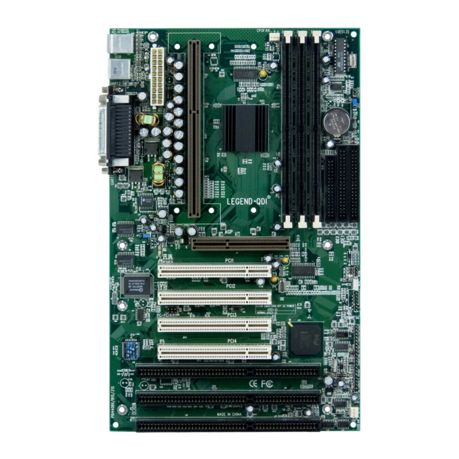
Introduction Introduction Overview The P6I440BX/BV is a high-performance, cost-effective, microATX motherboard which is centered on the Intel® 440BX AGPset. It provides 66MHz and 100MHz system bus support for all Intel Pentium® II and Celeron processors. Both 66MHz/100MHz SDRAM and 66MHz EDO DIMMs are supported. -
Page 8: On-Board Ide
Provides on-board Line-in Jack, Microphone-in Jack, speaker/Line-out Jack and MIDI/ Joystick Connector. Advanced features Provides Trend ChipAwayVirus® On Guard. Provides on-board PS/2 mouse and PS/2 keyboard ports. Two USB ports supported. Provides infrared interface. Supports Windows 95/98 software power-down. Manual for P6I440BX/BV... -
Page 9: Green Function
Supports IDE CD-ROM or SCSI boot up. Green function Supports ACPI (Advanced Configuration and Power Interface) and ODPM (OS Directed Power Management). Supports three green modes: Doze, Standby and Suspend. Expansion slots 2 PCI slots and 1 ISA/PCI shared slot. 1 AGP Slot Manual for P6I440BX/BV... - Page 10 -- This page is intentionally left blank -- Manual for P6I440BX/BV...
-
Page 11: External Connectors
You can enable/disable them and choose the IRQ or I/O address in “Integrated Peripherals” from AWARD BIOS SETUP. Parallel Port UART2 UART1 Manual for P6I440BX/BV... -
Page 12: Atx Power Supply Connector & Power Switch (Power)
Note: * If you change “soft-off by PWR-BTTN” from default “Instant-off” to “Delay 4 Secs” in the “POWER MANAGEMENT SETUP” section of the BIOS, the power button should be pressed for more than 4 seconds before the system powers down. Manual for P6I440BX/BV... -
Page 13: Reset Switch (Reset)
Hardware Green Connector (SLEEP) If the SecurityEasy function is enabled, push once the switch connected to this header and the system will enter lock status. If the lock function is disabled, push once the switch, the system enters suspend mode. Manual for P6I440BX/BV... -
Page 14: Infrared Header (Irda)
LAN adapter, set “Wake Up On LAN” as Enabled in the “POWER MANAGEMENT SETUP” section of the BIOS. Save & exit, then boot the operating system once to make sure this function takes effect. +5V standby Signal for waking up (active high) Manual for P6I440BX/BV... -
Page 15: Wake-Up On Internal Modem (Wom)
CD audio cable. AUXIN is an auxiliary audio connector. With the speakers con- nected to Line/Speaker-out jack, you can listen to audio from the CD-ROM drive. CDLIN(Sony) CD Right Channel CD Left Channel AUXIN AUX Right Channel AUX Left Channel Manual for P6I440BX/BV... - Page 16 (UART1) can’t be used. Sound Connector (PC-PCI)(manufacturing option) This connector is for the usage of PCI sound card. 5-GND SERIAL INTERRUPT REQUEST-6 PC/PCI DMA REQUEST-4 3-NC GND-2 1-PC/PCI DMA ACKNOWLEDGE Manual for P6I440BX/BV...
-
Page 17: Expansion Slots & I/O Ports Description
If you want to clear CMOS, unplug the AC power supply first, close JCC(pin1&pin2) once, set JCC back to the normal status with pin2&pin3 connected, then power on the system. Normal status: Clear CMOS: (Unplug the AC power supply) Manual for P6I440BX/BV... - Page 18 If you want to set the Line-out/Speaker-out jack as Line out, set JP10 & JP11 with pin2&pin3 closed. Otherwise, set JP10 & JP11 with pin1&pin2 shortened for Speaker out. JP10 JP11 Set as Line-out JP10 JP11 Set as Speaker-out Manual for P6I440BX/BV...
Need help?
Do you have a question about the P6I440BX and is the answer not in the manual?
Questions and answers