Table of Contents
Advertisement
Quick Links
Item Checklist
This item checklist is only available for retail market.Completely check your package,If you
discover damaged or missing items, contact your retailer.
Advance 10TM mainboard
QDI Driver CD 2000
User's manual
1 IDE ribbon cable
1 floppy ribbon cable
I/O shield(optional)
1 10-pin ribbon cable with bracket for USB3 and USB4(optional)
Notice
The information in this document is subject to change in order to improve reliability, design,
or function without prior notice and does not represent a commitment on the part of this
company. In no event will we be liable for direct, indirect, special, incidental, or consequen-
tial damages arising out of the use or the possibility of such damages.
All trademarks are the property of their respective owners.
If you need any further information, please visit our web-site: "www.qdigrp.com".
Advertisement
Table of Contents

Related Manuals for QDI Advance 10TM


Summary of Contents for QDI Advance 10TM
- Page 1 Item Checklist This item checklist is only available for retail market.Completely check your package,If you discover damaged or missing items, contact your retailer. Advance 10TM mainboard QDI Driver CD 2000 User’s manual 1 IDE ribbon cable 1 floppy ribbon cable...
- Page 2 þ EN 50082-1 Generic immunity standard Part 1: Residential, commercial and light industry European Representative: QDI COMPUTER ( UK ) LTD QDI COMPUTER ( SCANDINAVIA ) A/S QDI SYSTEM HANDEL GMBH QDI EUROPE B. V. QDI COMPUTER (FRANCE) SARL QDI COMPUTER HANDELS GMBH LEGEND QDI SPAIN S.L...
- Page 3 Declaration of conformity Trade Name: QDI Computer ( U. S . A. ) Inc. Model Name: Advance 10TM Responsible Party: QDI Computer ( U. S. A.) Inc. Address: 41456 Christy Street Fremont, CA 94538 Telephone: (510) 668-4933 Facsimile: (510) 668-4966...
-
Page 4: Table Of Contents
C O N T E N T S 1. Introduction.............1 Overview.................1 Key Features..............1 2. Installation Instructions ........4 External Connectors..........4 PS/2 Keyboard & PS/2 Mouse Connectors......4 USB1,USB2 connectors...........4 USB3,4Connectors............5 Parallel Port, Serial Port Connectors........5 Line-in, Microphone-in, Speaker-out jacks and MIDI/Joystick connector..........5 ATX Power Supply Connector &... - Page 5 Advanced Chipset Features Setup........29 Power Management Setup...........32 PNP/PCI Configuration Setup..........35 Integrated Peripherals............36 PC Health Status..............39 Password Setting..............40 Boot with BIOS defaults............40 Appendix ................41 QDI Driver Utility CD .............41 LogoEasy...................42 RecoveryEasy.................43 BIOS-ProtectEasy..............52 Norton AntiVirus..............52 ManageEasy................53 QDI SpeedEasy ..............54 QDI BootEasy................56 QDI StepEasy(optional)............57...
- Page 6 Caution 1. Be sure to add some Silicone Grease between the CPU and the heatsink of FAN to keep them fully contact , meanwhile to meet the heat sink requirement. 2. Never run the processor without the heatsink properly and firmly attached.
-
Page 7: Introduction
Chapter 1 Introduction Overview The Advance 10TM is a high performance, cost-effective and energy efficient mainboard for the implementation of desktop personal computer system from 66MHz, 100MHz to 133MHz based on Socket 370 processors. The green mainboard utilizes VIA Apollo Pro 133T chipset consisting of VT82C694T and VT82C686B. - Page 8 Provides onboard Line-in Jack, Microphone-in Jack, Speaker-out Jack with onboard amplifier and MIDI/Joystick Connector AGP Slot Supports AGP 4X AGP V2.0 compliant Advanced Features PCI- 2.2 compliant Provides Trend ChipAwayVirus® On Guard Supports wake-up on LAN Supports wake-up on internal/external modem Manual for Advance 10TM...
- Page 9 Chapter 1 Supports system monitoring( monitors system temperature, CPU temperature, voltages and fan speed ) Supports QDI innovations: SpeedEasy,ManageEasy, LogoEasy, RecoveryEasy ,BootEasy and BIOS-ProtectEasy,StepEasy(Optional) BIOS Licensed advanced AWARD(Phoenix) BIOS Supports Flash ROM with plug and play ready Supports IDE CDROM or SCSI bootup...
- Page 10 --This page is intentionally left blank--...
-
Page 11: Installation Instructions
Two USB ports are for connecting USB devices. USB1 USB2 Be sure to unplug the AC power supply before adding or removing expansion cards or other system peripherals, otherwise your motherboard and expan- sion cards might be seriously damaged. Manual for Advance 10TM... -
Page 12: Usb3,4Connectors
The Speaker-out jack allows you to connect to speakers or headphones for audio output from the internal amplifier.The MIDI/Joystick connector allows you to connect a game joystick or a MIDI device. MIDI/Joystick optional Microphone in Speaker out Line in Manual for Advance 10TM... -
Page 13: Atx Power Supply Connector & Power Switch(Power Sw)
The connector has an orientation. If one way doesn’t work, try the other way. Reset Switch (RESET) The connector connects to the case’s reset switch. Press the switch once, the system resets. Speaker Connector (SPEAKER) The connector can be connected to the speaker on the case. Manual for Advance 10TM... -
Page 14: Power Led Connector (Pwr Led)
The connector can be connected to the keyboard lock switch on the case for locking the keyboard. SPEAKER RESET GREEN LED KEYLK SLEEP POWER LED POWER ACPI LED SPEAKER GREEN LEDKEYLK RESET ACPI POWER POWER SLEEP Manual for Advance 10TM... -
Page 15: Wake-Up On Lan (Wol)
Then connect this header to the relevant connector on the modem card, set “Wake up on LAN/Ring ” as Enabled in the “POWER MANAGEMENT SETUP” section of the BIOS. Save & exit, then boot the operating system once to make sure this function takes effect. +5V Standby Signal for waking up Manual for Advance 10TM... -
Page 16: Audio Connectors ( Cd_In,Modem)
The fan speeds of CPUFAN and CHSFAN can be detected and viewed in “PC Health” section of the BIOS. They will be automatically turned off after the system enters suspend mode. FAN GND +12V BAKFAN FAN GND +12V CPUFAN SENSE SENSE FAN GND +12V CHSFAN Manual for Advance 10TM... -
Page 17: Infrared Header (Irda)
To avoid conflict, the onboard audio can be disabled in BIOS when using AMR Audio Riser card. AMR Slot Disable AMR Primary Sound Enable Onboard Audio Pin2-Pin3 closed Enable AMR Primary Sound Pin1-Pin2 closed Disable Onboard Audio Note: The Advance 10TM mainboard supports Primary AMR card only. Manual for Advance 10TM... -
Page 18: Audio Interface
Front LINE Out( R ) LINE Next( R ) Front LINE Out( L ) LINE Next( L ) GND (FLO) (Cut away ) FrontLineOutR LineNextR Speaker LineNextL (Active Audio) FrontLineOutL Front Audio jack FAUDIO (Audio Interface) 9 13 Manual for Advance 10TM... -
Page 19: Chassis Security Switch (Chssec)
If the chassis has been opened , the system will record the status and indicate the chassis has been opened. You can receive this information from QDI ManageEasy software. CHSSEC... -
Page 20: Jumper Settings
“Auto”, the system will detect the CPU FSB speed automatically. If they are set as “Jumper”, the CPU FSB speed can be set by jumpers manually. JFSB2 JFSB1 FSB SETTING JFSB2 JFSB1 Auto (Default) Close Close Jumper Open Open Manual for Advance 10TM... -
Page 21: Overclocking Jumper Setting (Jclk1, Jclk2)
Whether or not your system can be overclocked depends on your processor’s capability. We do not guarantee the overclocking system to be stable. Warning: Be sure your selection is right. CPU over speed will be dangerous! We will not be responsible for any damages caused. Manual for Advance 10TM... -
Page 22: Cpu Bus Ratio Selection(Jx1,Jx2,Jx3,Jx4)
Only unlocked processors can adjust specified bus ratio through hardware jumper setting. Warning: Be sure your selection is right. CPU over speed will be dangerous! We will not be responsible for any damages caused. Manual for Advance 10TM... -
Page 23: Clear Cmos(Jcc)
CPU well. If the jumpers are set as “Auto”, the system will detect the CPU core voltage automatically. The voltage listed in the table is theoretical value,”1-2” represents pin1 and pin2 closed; ”2-3” represents pin2 and pin3 closed,”open” represents all pins opened. Manual for Advance 10TM... - Page 24 1.775 open open 1.80 open open open 1.825 Auto Warning: To set CPU core voltage higher than its default core voltage is not suggested. If you do, we will not be responsible for any damages caused. Manual for Advance 10TM...
-
Page 25: Bios Protection Function Jumper (Jav)
DMI information update will be fail. The mainboard provides the BootEasy function.If you want to use this function,Please set the jumper JAV as open under PC will boot-up in normal way conditions. Refer to the BootEasy introduction. Manual for Advance 10TM... -
Page 26: Enable/Disable On-Board Audio (Jsd)
ACPI S3 by activating USB Device. Furthermore, the item “ USB Resume from S3”in BIOS should also be set correspondingly to enable or disable this function. Disable: 1 2 3 JUSB Enable: 1 2 3 JUSB Manual for Advance 10TM... -
Page 27: Bios Description
1. Create a bootable system floppy diskette by typing Format A:/s from the DOS prompt under DOS6.xx or Windows 9x environment. 2. Copy AWDFLASH.EXE (version>=7.73) from the directory \Utility located on QDI Mainboard Utility CD onto your new bootable diskette. -
Page 28: Award(Phoenix) Bios Description
The basic CMOS settings included in “Standard CMOS Features” are Date, Time, Hard Disk Drive Types, Floppy Disk Drive Types, and VGA etc. Use the arrow keys to highlight the item, then use the <PgUp> or <PgDn> keys to select the value desired in each item. Manual for Advance 10TM... - Page 29 ‘Manual’, the related information should be entered regarding the following items. Enter the information directly from the keyboard and press < Enter>: CYLS number of cylinders HEAD number of heads PRECOMP write pre-compensation LANDZ landing zone SECTOR number of sectors MODE HDD access mode Manual for Advance 10TM...
- Page 30 To support LBA or LARGE mode of HDDs, there must be some softwares involved which are located in Award HDD Service Routine(INT13h).It may fail to access a HDD with LBA (LARGE) mode selected if you are running under an Operating System which replaces the whole INT 13h. Manual for Advance 10TM...
- Page 31 The POST of the BIOS will determine the amount of base (or conventional) memory installed in the system. Extended Memory The BIOS determines how much extended memory is presented during the POST. Total Memory Total memory of the system . Manual for Advance 10TM...
-
Page 32: Cpu Speedeasy Setup
Disable Spread Spectrum. CPU Host/PCI Default Select the CPU host clock and PCI clock. Clock Warning: Do not set CPU frequency higher than its working frequency. If you do, we will not be responsible for any damages caused. Manual for Advance 10TM... -
Page 33: Advanced Bios Features Setup
Enables CPU L2 Cache ECC function. ECC Checking Disabled Disables CPU L2 Cache ECC function. ® Processor Enabled Pentium III Processor Number can be readable. ® Disabled Number Feature Pentium III Processor Number can be unreadable. Manual for Advance 10TM... - Page 34 Disabled Video shadow is disabled. l C8000~CBFFF Enabled Optional ROM will be copied to RAM by 16K bytes Shadow per unit..DC000-DFFFF Shadow: Disabled The shadow function is disabled. Manual for Advance 10TM...
- Page 35 BIOS from being attacked by severe virus such as CIH. Therefore disable this item only when wanting to flash BIOS, afterwards set this item as Enabled (default). Disabled Disabling this item allows you to upgrade the BIOS. Manual for Advance 10TM...
-
Page 36: Advanced Chipset Features Setup
Do not set this memory hole. l P2C/C2P Enabled Enabled P2C/C2P concurrency. Concurrency Disabled Disable P2C/C2P concurrency. Enabled System BIOS Beside conventioal memory, system BIOS area is Cacheable also cacheable. Disabled System BIOS area is not cacheable. Manual for Advance 10TM... - Page 37 Disable CPU to PCI Write Buffer. l PCI Dynamic Enabled Enable PCI Dynamic Bursting. Bursting Disabled Disable PCI Dynamic Bursting. l PCI Master 0 WS Enabled Enable PCI Master 0 WS Write. Write Disabled Disable PCI Master0 WS Write. Manual for Advance 10TM...
- Page 38 AGP Master 1 WS Enabled Enable AGP Master 1 WS Read. Disabled Read Disabled AGP Master 1 WS Read. Memory Parity/ECC Enabled Enables the Error Checking&Correction if ECC Check memory is used. Disabled Disable the ECC function. Manual for Advance 10TM...
-
Page 39: Power Management Setup
Defines the continuous idle time before the system enters Doze mode. Suspend Mode Disabled The system never enters Suspend mode by timer. 1Min ~ 1Hr Defines the continuous idle time before the system enters Suspend mode. Manual for Advance 10TM... - Page 40 Enabled USB Resume The system could be waken up by USB Device from S3 from the Suspend to RAM status. Disabled The system cannot be waken up by USB Device from the Suspend To RAM status. Manual for Advance 10TM...
- Page 41 RTC has no alarm function. Primary INTR Allows wake up from IRQ. Does not Allows wake up from IRQ. Press Enter Reloads global timer. IRQs Activity Monitoring IRQ3~IRQ15 Enabled Enables IRQ3~IRQ15 to wake up. Disabled Disables IRQ3~IRQ15 to wake up. Manual for Advance 10TM...
-
Page 42: Pnp/Pci Configuration Setup
Does not assign an IRQ for the VGA card, in order to release the IRQ. Assign IRQ For Enabled Assigns an IRQ for USB. If an USB device is used enables this item. Disabled Does not assign an IRQ for USB. Manual for Advance 10TM... -
Page 43: Integrated Peripherals
Initializes the PCI VGA first. If a PCI VGA card and an AGP card are installed together in the system, the one initialized first functions. Initializes the AGP first. IDE HDD Block Enabled Allows IDE HDD to read/write several sectors Mode at once. Manual for Advance 10TM... - Page 44 EPP1.7 Onboard Legacy Enabled the following item according as onboard audio to Audio set. Disabled Sound Blaster Enabled Enabled Sound Blaster. Disabled Disabled Sound Blaster. SB I/O Base 220H/240H Define SB I/O Base Address. 260H/280H Address Manual for Advance 10TM...
- Page 45 SB DMA Select DMA0~DMA3 Select SB DMA . MPU-401 Enabled Enable MPU-401. Disabled Disable MPU-401. MPU-401 I/O 300-303H Define MPU-401 I/O address..Address 330-333H Game port Enabled Enable game port. (200-207H) Disabled Disable game port. Manual for Advance 10TM...
-
Page 46: Pc Health Status
2.49 significant voltages of the mainboard. +3.3V, 3.3V 3.32V +2.5V, +12V and 5V are voltages from the 4.83V ATX power supply, Vcore Voltage is the 11.79V CPU core voltage from the on board switching power supply. Manual for Advance 10TM... -
Page 47: Password Setting
If you have made all the changes to CMOS values and the system can not boot with the CMOS values selected in setup, clear CMOS after power-down, then power on again. System will boot with BIOS default settings. Manual for Advance 10TM... -
Page 48: Appendix
Appendix QDI Driver CD 2000 A QDI Driver CD 2000 is supplied with this mainboard. Insert CD 2000 that came with your mainboard into your CD-ROM drive to bring up the screen, click the options to install. The contents contained in it are showed as below: Install Driver It’s recommended for most users that program will be installed with the most common... -
Page 49: Logoeasy
When you power on or reset your system, the picture shown below will be displayed on the screen. You can use “CBLOGO.EXE” (included on the QDI Mainboard Utility CD) to replace it by any other logo which you prefer. Please you follow these steps to use CBLOGO.EXE Utility: 1. -
Page 50: Recoveryeasy
RecoveryEasy Introduction: RecoveryEasy, the latest QDI innovation, is able to protect the system from being destroyed, by creating a so-called “mirror partition” for a current hard disk partition and backuping all the data to the mirror area. This ideal utility provides disk partition, disk data backup/recov- ery, CMOS settings backup/recovery and multi-boot functions. - Page 51 In Windows system 1,048,576 bytes equal 1 Megabyte, while in RecoveryEasy 1,000,000 bytes equal 1 Megabyte, therefore a smaller size will be displayed in Windows system compared with the size displayed in RecoveryEasy. Manual for Advance 10TM...
- Page 52 : After RecoveryEasy is uninstalled, all the mirror areas have been disconnected with the relate partitions. If no partition is deleted or changed in size, or no other partition is created, users have chance to “Recover existing RecoveryEasy settings” when next time entering RecoveryEasy partition Manual for Advance 10TM...
- Page 53 If the partition chosen has been backuped before, a warning message will be shown, and the time when last backup was done will be displayed in the status line. After confirming the warning message, the system performs the backup. By pressing “N” or “ESC” key, the system quits. Manual for Advance 10TM...
- Page 54 In order to implement this function, users need to enable the switch when installing the OS or modifying the partition properties. Please note: Do not create or delete partitions or change the partition size when modifying the partition properties. Manual for Advance 10TM...
- Page 55 : When two or more than two hard disks are installed on the system, use F5 key to choose the hard disk. When processing a certain hard disk, F5 key can be used to choose the partition. Manual for Advance 10TM...
- Page 56 This is a way to protect the system from the errors of data accessing caused by changing HDD access mode. When RecoveryEasy detects such things, the system will be locked, users could reboot the system and set the HDD access mode as the original one in BIOS SETUP. Manual for Advance 10TM...
- Page 57 For example on the hard disk, partition C contains DOS, partition D contains Windows 95 version, partition E contains Windows 98 version, when activating partition C in RecoveryEasy, the system enters DOS, when activating partition E, the system enters Windows 98 version. Manual for Advance 10TM...
- Page 58 Recovery User Interface. Remember to create a mirror partition and backup before virus attacks the system. Manual for Advance 10TM...
-
Page 59: Bios-Protecteasy
The list below shows the most important tasks Norton AntiVirus helps you perform:Scan for viruses on your computer;Remove viruses from your computer;Update your virus protection with LiveUpdate;Quarantine an infected file. you can go to the Symantec Web site to view an online tutorial: http://www.symantec.com/techsupp/tutorial/nav2001 Manual for Advance 10TM... -
Page 60: Manageeasy
Today, it is possible to monitor and manage your complex hardware from Windows 9X and Windows NT. QDI ManageEasy is a system tool, like a bridge between the complex hardware and OS, used to access hardware status and to execute some control functions. It supports stron- ger functions for Windows 9X and Windows NT. -
Page 61: Qdi Speedeasy
Switch on power to the system and press the <Del> key to enter BIOS Setup. 4. Enter “CPU SpeedEasy Setup” menu to set up the CPU speed. 5. Save and exit BIOS Setup, your system will now boot successfully. Manual for Advance 10TM... - Page 62 The processor speed can be manually selected on the “CPU SpeedEasy SETUP” menu screen. Warning: Do not set CPU frequency higher than its working frequency. If you do, we will not be responsible for any damages caused. Manual for Advance 10TM...
-
Page 63: Qdi Booteasy
Appendix QDI BootEasy BootEasy is a new member of legend QDI Easy series, which is the latest innovation comes from legend QDI. BootEasy Setup Menu BootEasy technology enormously improves the long BOOT process time of computers. Reducing the wait time every user has to suffer when starting their computer. BIOS without BootEasy has to perform many routines every time when the system starts, such as checking system core of the computer and initializing system peripherals. -
Page 64: Qdi Stepeasy(Optional)
Installation You can install the QDI StepEasy by the following two means: 1. Run CD, select the installation of QDI StepEasy, then, act step by step according to the interface prompt. 2. Browse CD and run the setup.exe in the relative directory. - Page 65 6. When click on the “Min” button, the utility will minimize to an icon in the right-bottom task tray. Whenever click on the QSE(QDI StepEasy ) icon in the task tray, the utility will be activated in the current window.
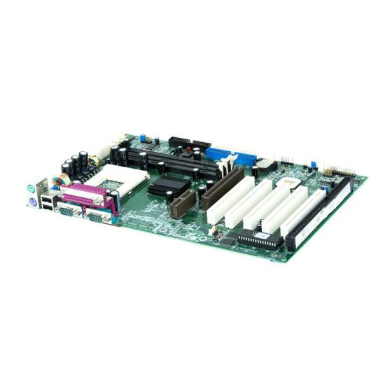
- Page 66 Mainboard Layout Mainboard Layout This layout is just for your reference...
Need help?
Do you have a question about the Advance 10TM and is the answer not in the manual?
Questions and answers