Table of Contents
Advertisement
Quick Links
Advertisement
Table of Contents

Related Manuals for QDI Brilliant IV


Summary of Contents for QDI Brilliant IV
- Page 1 ® PENTIUM P6I440BX/D Brilliant IV...
- Page 2 Notice The information in this document is subject to change in order to improve reliability, design, or function without prior notice and does not represent a commitment on the part of this company. In no event will we be liable for direct, indirect, special, incidental, or consequential damages arising out of the use or the possibility of such damages.
- Page 3 Residential, commercial and light industry European Representative: QDI COMPUTER ( UK ) LTD QDI COMPUTER ( SCANDINAVIA ) A/S QDI SYSTEM HANDEL GMBHQDI COMPUTER ( NETHERLANDS) B. V. QDI COMPUTER (FRANCE) SARL QDI COMPUTER HANDELS GMBH QDI COMPUTER (ESPANA) S.A.
- Page 4 Trade Name: QDI Computer ( U. S . A. ) Inc. Model Name: P6I440BX/DP Brilliant IV Responsible Party: QDI Computer ( U. S. A.) Inc. Address: 41456 Christy Street Fremont, CA 94538 Telephone: (510) 668-4933 Facsimile: (510) 668-4966 Equipment Classification:...
-
Page 5: Table Of Contents
Contents 1. Introduction--------------------------------------------------------------1 Overview --------------------------------------------------------------------1 Key Features ----------------------------------------------------------------1 2. Power Supply Requirements ------------------------------------------7 Power ------------------------------------------------------------------------7 Currents ---------------------------------------------------------------------7 3. SecurityEasy -------------------------------------------------------------9 System Password -----------------------------------------------------------9 SecurityEasy ----------------------------------------------------------------9 4. Quick Installation-------------------------------------------------------11 Quick Jumper Setting -----------------------------------------------------12 CPU Frequency Multiple table -------------------------------------------13 5. System Setting by Jumper ---------------------------------------------15 CPU Frequency Selection -------------------------------------------------15 Clear CMOS ----------------------------------------------------------------17 Memory Configuration ----------------------------------------------------17... - Page 6 Contents Speaker Connector---------------------------------------------------------22 Power LED Connector ----------------------------------------------------22 Key Lock Connector -------------------------------------------------------22 Status LED Connector-----------------------------------------------------23 Green/Lock Connector ----------------------------------------------------23 Infrared Header-------------------------------------------------------------23 Cooling Fan Connectors --------------------------------------------------24 Chassis Security ------------------------------------------------------------24 Wake On Internal Modem Connector-----------------------------------24 I/O Port and Slot Description --------------------------------------------25 7. AWARD BIOS Description ------------------------------------------29 Entering Setup--------------------------------------------------------------29 Load Setup Defaults -------------------------------------------------------29 Standard CMOS Setup ----------------------------------------------------30...
-
Page 7: Introduction
Chapter 1 Chapter 1 Introduction Overview P6I440BX/DP Brilliant IV mainboard is designed for servers and workstations. It is a high-performance and powerful system for dual ® Pentium II processors, which provides onboard LAN for fast Ethernet network at 10/100Mbps, onboard Ultra Wide SCSI at 40MB/sec, RAID and system health monitor support. - Page 8 Introduction System memory • Four 168-pin DIMM sockets • 3.3V only DIMM DRAM configuration. • Synchronous 100-MHz or 66-MHz SDRAM • 4-Mbit, 16-Mbit, 64-Mbit and 128-Mbit DRAM devices. • For up to 512MB standard SDRAM memory. • For up to 1GB Registered SDRAM DIMM memory. •...
- Page 9 Chapter 1 Onboard SCSI • Adaptec AIC-7880 PCI to SCSI controller which is equivalent to Adaptec AHA-2940UW PCI SCSI Controller. • Both Ultra wide, narrow SCSI interface • Data transfer rate up to 40MB/Sec • Driver for Netware, Windows NT, OS/2, SCO Unix, Unixware. With 1 RAID port, RAID function (RAID0, 1, 0/1 and 5) are supported •...
- Page 10 Introduction • On board LM80 supports system monitoring (monitor system voltages, temperature, chassis intrusion and FAN speed)) • Provides LogoEasy function • ® Provides ManageEasy function ( optional) • LM75 monitors the temperature of the CPU (Optional) • Supports LDCM(LanDesk Client Manager) software (Optional) •...
- Page 11 Chapter 1 • Complies with the A.G.P specification Rev 1.0 • Support for +3.3V A.G.P -66/133 devices • Synchronous complying with the host bus frequency Expansion slots • 2 x ISA slots and 4 x PCI slots • 1 AGP Slot •...
- Page 12 Introduction -- This page is intentionally left blank --...
-
Page 13: Power Supply Requirements
Chapter 2 Chapter 2 Power Supply Requirements The Brilliant IV green mainboard supports the industry standard ATX power supplies. Check the ratings of the power supply installed to ensure that they meet the following requirements. Power Normally the maximum rating power for the power supply installed should be at least 250W. - Page 14 Power Supply Requirements -- This page is intentionally left blank --...
-
Page 15: Securityeasy
CMOS setup menu. SecurityEasy The Brilliant IV provides additional SecurityEasy function to protect the system from unauthorized entry or use. If the Lock function is enabled, there are two ways to enter LOCK status. - Page 16 SecurityEasy Please read the notes below thoroughly. Note 1: The Green function and the Lock function can not be enabled at the same time. Note 2: If no Administrative Password has been set by user, the system will never enter the LOCK status. Note 3: When entering the Administrative password to exit the LOCK status, you must use the normal <Enter>...
-
Page 17: Quick Installation
Chapter 4 Chapter 4 Quick Installation The Brilliant IV is shipped with the following manufacture default: • CPU frequency multiple at 3x (200/66MHz or 300/100MHz Pentium®II) • LAN Chip(Intel 82558) Enabled • SCSI Chip(Adaptec 7880) Enabled Duplicate the following steps to perform a quick installation of your computer. -
Page 18: Quick Jumper Setting
Exit the “ Setup Menu ” screen and save the setup data. Step 8. Enjoy the Brilliant IV The Brilliant IV is a high-performance, powerful system. *Note: Please refer to Chapter 6 for details on Hardware Installation. - Page 19 Chapter 4 *Note: Please refer to chapter 5 for details on jumper setting .
-
Page 20: Cpu Frequency Multiple Table
Quick Installation CPU Frequency multiple table FREQ.MUT CLOSE CLOSE CLOSE CLOSE OPEN CLOSE CLOSE CLOSE 3 (default) CLOSE OPEN CLOSE CLOSE OPEN OPEN CLOSE CLOSE CLOSE CLOSE OPEN CLOSE OPEN CLOSE OPEN CLOSE CLOSE OPEN OPEN CLOSE OPEN OPEN OPEN CLOSE... - Page 21 Chapter 4 -- This page is intentionally left blank --...
-
Page 23: System Setting By Jumper
Chapter 5 Chapter 5 System Setting by Jumper The Brilliant IV offers a set of jumper settings to facilitate clock frequency adjustment and other important selections. CPU Frequency Selection According to CPU’s specification, set the CPU clock speed carefully. If only one CPU is used, the GTC(GTL Terminator Card) must be plugged into the other slot. - Page 24 System Setting by Jumper ® ® ® ® Pentium II350MHz=3.5x100MH Pentium II 400MHz= 4x100MH JX4 JX3 JX2 JX1 JX4 JX3 JX2 JX1 ® ® Pentium II450MHz=4.5x100MH JX4 JX3 JX2 JX1 Warning Set CPU’s clock speed according to its specification. CPU over speed will be dangerous!
-
Page 25: Clear Cmos
CMOS. Memory Configuration The P6I440BX/DP Brilliant IV main board supports up to four 168PIN 3.3V un-buffered 100MHz/66MHz DIMM, provides a flexible size from 8MB up to 512MB SDRAM memory or 8MB up to 1GB Registered SDRAM memory. -
Page 26: Onboard Scsi Selection
System Setting by Jumper Onboard SCSI Selection JP10 enables or disables the onboard SCSI controller. Please see the table listed below. JP10 Comment Close (Default) Onboard SCSI controller is ENABLED. Open Onboard SCSI controller is DISABLED. SCSI Terminator Control JP17 powers-down or powers-up the onboard SCSI terminators. -
Page 27: Onboard Lan Selection
Chapter 5 Onboard LAN Selection JP15 enables or disables the onboard LAN controller . JP15 Comment Close (Default) Onboard LAN controller is ENABLED. Open Onboard LAN controller is DISABLED. - Page 28 System Setting by Jumper --This page is intentionally left blank --...
-
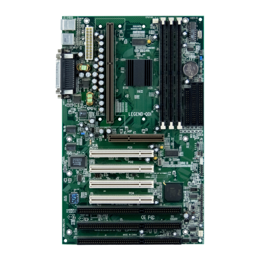
Page 29: Mainboard Connectors
Chapter 6 Chapter 6 Mainboard Connectors This section lists connector pin assignment and port description on the main- board. The discriptions of the connectors and ports are illustrated in the following figures. Before inserting these connectors, please pay attention to the directions. -
Page 30: Hard Disk Led Connector
Mainboard Connectors Hard Disk LED Connector(HD_LED) PIN NUMBER FUNCTION LED Anode LED Cathode LED Cathode LED Anode Reset Switch (RESET) SETTING FUNCTION CLOSE ONCE RESET THE SYSTEM OPEN NORMAL Speaker Connector(SPEAKER) PIN NUMBER FUNCTION SPKDATA Power LED Connector (PW_LED) PIN NUMBER FUNCTION LED Anode LED Cathode... -
Page 31: Status Led Connector
Chapter 6 Status LED Connector(GRN_LED) The LED connected to the “GRN_LED” shows the status of the system as the following table describes. Status LED Indication Meaning No power supply or the current of 5VSB is not strong enough. The system is in Power-up status. Flashing at a frequency about 1.5Hz The system is in soft Power-down status. -
Page 32: Cooling Fan Connectors
Chassis Security (J18): Leave it Open if the chassis is closed. Close it if the chassis is opened. Note* Please refer to QDI’s ManageEasy CD-ROM for more information about “Chassis Security”. Wake On Internal Modem Connector (WOM) PIN NUMBER... -
Page 33: I/O Port And Slot Description
Chapter 6 I/O Port and SLOT Description I/O Port and SLOT Description (See Board layout) (See Board layout) CONNECTOR FUNCTION IDE1 Primary IDE Port IDE2 Secondary IDE Port FLOPPY Floppy Drive Port PRINTER Parallel Port UART1 COM1/COM2/COM3/COM4 UART2 COM2/COM3/COM4/COM1 USB1 First USB Port USB2 Second USB Port... - Page 34 Mainboard Connectors used for RAID port card. RAID Port The mainboard with the embedded SCSI can be turned to assist the RAID ready by adding the Adaptec ARO-1130 adapter. This RAID port option after adding the Adaptec ARO- 1130 adapter can support: Bus Master DMA Up to 133 Mbyte/Sec Burst rate RAID 5, 1, 0 and 0/1...
- Page 35 Chapter 6 Note 3: Internal narrow SCSI peripherals and internal wide SCSI peripherals can be used at the same time. There is one exception here. When both internal SCSI peripherals and external SCSI peripherals are used (connected by the optional external wide SCSI cable with bracket) at the same time, only four kinds of configuration are executable.
- Page 36 Mainboard Connectors The SCSI ID0 is best used for the SCSI hard disk as your computer’s boot device; ID1 is best reserved for a secondary SCSI hard disk. (Only when you use the SCSI hard disks and devices.)
-
Page 37: Award Bios Description
Chapter 7 Chapter 7 AWARD BIOS Description Entering Setup Power on the computer, when the following message appears briefly at the bottom of the screen during the POST (Power On Self Test), press <Del> key or simultaneously press <Ctrl> + <Alt> + <Esc> keys. Press <Del>... - Page 38 AWARD BIOS Description Use the arrow keys to highlight the item, then use the < PgUp> or <PgDn> keys to select the value you want in each item. ROM PCI/ISA BIOS(2A69KQ19) STANDARD CMOS SETUP AWARD SOFTWARE, INC Date (mm:dd:yy) : Thu, Mar, 3, 1998 Time (hh:mm:ss) : 17:27:52 HARD DISKS...
- Page 39 Chapter 7 CYLS number of cylinders HEAD number of heads PRECOMP write pre-compensation LANDZ landing zone SECTOR number of sectors MODE HDD access mode Video There are two ways to boot up the system: I. When VGA is used as primary and monochrome is used as secondary, the selection of the video type is “EGA/VGA”...
- Page 40 AWARD BIOS Description Memory The category which is determined by POST (Power On Self Test) of the BIOS, is non-modifiable. Base Memory The POST of the BIOS will determine the amount of base (or conventional) memory installed in the system. Extended Memory The BIOS determines how much extended memory is presented during the POST.
-
Page 41: Bios Features Setup
Chapter 7 BIOS Features Setup ROM PCI/ISA BIOS (2A69KQI9) BIOS FEATURES SETUP AWARD SOFTWARE, INC. Virus Warning : Disabled Video BIOS Shadow :Enabled Pentium(R)II L1 Cache : Enabled C8000 CBFFF Shadow :Disabled Pentium(R)II L2 Cache : Enabled CC000 CFFFF Shadow :Disabled Pentium(R)II L2 Cache ECC : Enabled... - Page 42 AWARD BIOS Description Note:This function is available only for DOS and other OS that does not trap INT13. • Pentium(R)II Enabled Enables Pentium® II internal Level1/Level2 cache. L1/L2 Cache Disabled Disables Pentium® II internal Level1/Level2 cache. • Pentium(R)II Enabled Enables Pentium® II L2 cache ECC(Error Checking L2 Cache ECC and Correction) function.
- Page 43 Chapter 7 (Chars/Sec) second). • Typematic 250~1000 Sets the time of the typematic delay. Delay (Msec) • Password System The system will not boot and access to Setup will be Setting denied if the correct password was not entered when prompted.
-
Page 44: Chipset Features Setup
AWARD BIOS Description Chipset Features Setup ROM PCI/ISA BIOS (2A69KQI9) CHIPSET FEATURES SETUP AWARD SOFTWARE, INC. Auto Configuration : Enabled Auto Detect DIMM/PCI Clk : Enabled EDO DRAM Speed Selection : 60ns EDO CASx# MA Wait State EDO RASx# Wait State SDRAM CAS Latency Time DRAM Data Integrity Mode : Non-ECC... - Page 45 Chapter 7 not affected by this bit. Without additional wait state. • EDO RASx# Wait One additional wait state is inserted before State RASx# is asserted for row misses. This provides one clock of additional MAX[13:0] setup time to RASx# assertion. This bit does not affect page misses since the MAX[13:0] lines are setup several clocks in advance of RASx# assertion for page misses.
-
Page 46: Power Management Setup
AWARD BIOS Description Power Management Setup ROM PCI/ISA BIOS (2A69KQI9) POWER MANAGEMENT SETUP AWARD SOFTWARE, INC. ACPI function :Disabled ** Reload Global Timer Events ** Power Management :User Define IRQ [3-7,9-15], NMI :Enabled PM Control by APM :Yes Primary IDE 0 :Disabled Video Off Method :V/H SYNC+Blank... - Page 47 Chapter 7 are in their MAX values Max Saving Pre - defined timer values are used so that all timers are in their MIN value • PM Control System BIOS will ignore APM when Power by APM Management is enabled. System BIOS will wait for APM’s prompt before it enters any PM mode e.g.
-
Page 48: Pnp/Pci Configuration
AWARD BIOS Description • Suspend Mode Disabled The system will never enter Suspend mode. 1 Min ∼ 1Hr Defines the continuous idle time before the system entering Suspend mode. If any item defined in “Wake Up Events In Suspend” is On and activated, the system will be waken up. - Page 49 Chapter 7 ROM PCI/ISA BIOS (2A69KQ19) PNP/PCI CONFIGURATION AWARD SOFTWARE, INC PNP OS Installed : No PCI Slot 1 Use IRQ No. : Auto Resources Controlled By : Manual PCI Slot 2 Use IRQ No. : Auto Reset Configuration Data : Disabled PCI Slot 3 Use IRQ No.
- Page 50 AWARD BIOS Description this item as Disabled. Disabled Does not force updating ESCD. • ∼ IRQ-3 IRQ-15 assigned Legacy ISA The specified IRQ-x will be assigned to ISA only. PCI/ISA PnP The specified IRQ-x will be assigned to ISA or PCI. •...
-
Page 51: Integrated Peripherals
Chapter 7 Integrated Peripherals ROM PCI/ISA BIOS (2A69KQ19) INTEGRATED PERIPHERALS AWARD SOFTWARE, INC. IDE HDD Block Mod : Enabled Onboard Parallel Port : 378/IRQ7 IDE Primary Master PIO : Auto Parallel Port Mode : SPP IDE Primary Slave PIO : Auto IDE Secondary Master PIO : Auto IDE Secondary Slave PIO... - Page 52 AWARD BIOS Description • IDE Auto Ultra DMA mode will be enabled if ultra Primary/ Secondary DMA device is detected. Master/Slave UDMA Disabled Disables this function. • On-chip Enabled On-chip primary/secondary PCI IDE port is Primary/Secondary enabled. PCI IDE Disabled On-chip primary/secondary PCI IDE port is disabled.
-
Page 53: System Monitor Setup
Chapter 7 System Monitor Setup ROM PCI/ISA BIOS (2A69KQ19) SYSTEM MONITOR SETUP AWARD SOFTWARE , INC. Shutdown Temperature : Disabled Current CPU1 Temperature : 0°C/32°F Current CPU2 Temperature : 0°C/32°F Current System Temp. : 32°C/89°F Current CPUFAN1 Speed : 4821RPM Current CPUFAN2 Speed : 0 RPM Current Chassis Fan Speed... - Page 54 AWARD BIOS Description • Current CPUFAN1 RPM (Revolution Per Minute) Speed of fan Speed which is connected to the fan header Current CPUFAN2 CPUFAN1, CPUFAN2, CHSFAN Speed BAKFAN. Fan speed value is based on an Current Chassis FAN assumption that tachometer signal is two pulses Speed per revolution;...
-
Page 55: Securityeasy Setup
Chapter 7 SecurityEasy Setup ROM PCI/ISA BIOS (2A69KQ19) SecurityEasy SETUP AWARD SOFTWARE , INC. Lock Function select : Enable Administrative Password : Enter Keyboard Inactive Timer : Disable Floppy Access Control : Read Only Video Blanking Control : Enable ↑↓→← : Select Item ESC: QUIT F1 : Help PU/PD/+/- : Modify... - Page 56 AWARD BIOS Description • Keyboard Inactive Timer Disable The system will not enter the LOCK mode due to the Keyboard Inactive Timer. 1Min~ Set the continuous idle time of keyboard before 1Hour the system entering the LOCK mode. • Floppy Access Control The Floppy is Read/Writable.
-
Page 57: Password Setting
Chapter 7 Password Setting When you select this function, the following message will appear at the center of the screen to assist you in creating a password. ENTER PASSWORD Type the password, up to eight characters, and press <Enter>. The password typed now will clear any previously entered password from CMOS memory. -
Page 58: Ide Hdd Auto Detection
AWARD BIOS Description IDE HDD Auto Detection The Enhanced IDE features was included in all Award BIOS. Below is a brief description of these features. ROM PCI/ISA BIOS (2A69KQ19) CMOS SETUP UTILITY AWARD SOFTWARE, INC. HARD DISKS TYPE SIZE CYLS HEAD PRECOMP LANDZ SECTOR MODE Primary Master: Select Primary Master Option (N=Skip): N Option Size... - Page 59 Chapter 7 2. HDD Modes The Award BIOS supports 3 HDD modes: NORMAL, LBA and LARGE, also Auto detect. NORMAL Generic access mode in which neither the BIOS nor the IDE controller will make any transformation during accessing. The maximum number of cylinders, heads and sectors for NORMAL mode are 1024,16 and 63.
-
Page 60: Power-On Boot
AWARD BIOS Description Power - On Boot If you have made all the changes to CMOS values and the system can not boot with the CMOS values selected in Setup, restart the system by turning it OFF then ON or press the “RESET” button on the system case. You may also restart the system by simultaneously pressing the <... -
Page 61: Appendix. Utility Diskette
Appendix Appendix A. Utility Diskette You may use this diskette to update your BIOS when necessary. For the most updated and additional information about BIOS upgrade, please refer to “README” in the “Utility Diskette”. Warning: 1. We strongly recommend that you only upgrade BIOS when it is really necessary. -
Page 62: Installation Procedures
Appendix ® Retention Mechanism & Pentium II Processor Installation Procedures (Single CPU shown) 1. Insert the two Retention Mechanism Attach Mounts up through the bottom of the mainboard. Two Retention Mechanism Attach Mount 2. Place Plastic Guide with captive nuts on mainboard, then fasten all the four nuts. Plastic Guide with four nuts Note: Please pay attention to the direction of the window. - Page 63 Appendix HSSBASE 4. Insert Pentium ® II Processor in Slot1.
- Page 64 Appendix 5. Clip Plastic Bar onto the HSSBASE through the fins on the processors’ heatsink. 6. The Retention Mechnism installation procedure is completed as shown below. Remark: Please skip step3 and step5 for Boxed Pentium ® II Processor and refer to relevant details of this kind of processor for your installation.
-
Page 65: Logoeasy
If you prefer not to show any logo on the screen while booting up, set “Disabled” to the “Show Bootup Logo” option. Please refer to page 35. We reserve the right of modifying the default full-logo of QDI without further notification. -
Page 66: Manageeasy
AMA, the administrator can do remote monitoring and managing. Using AMA, you can detect or view system information and PC health status for any computer that has installed QDI ManageEasy system. If you have the privilege, special operations can be done on the remote computer, such as watching screen, sending message, shutdown or restart etc. - Page 67 Weitere Informationen sind abrufbar unter der QDI • Worldwide-Webseite: “ ” http://www.qdigrp.com Francais Plus amples renseignements peuvent être obtenus en • s’ adressant au site mondial de QDI désigné par “ ” http://www.qdigrp.com Italiano Per ottenere ulteriori informazioni, consultate il sito • Internet all’indirizzo “...
Need help?
Do you have a question about the Brilliant IV and is the answer not in the manual?
Questions and answers