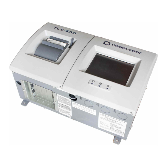
Veeder-Root TLS-4 Series Console Hardware Replacement
Hide thumbs
Also See for TLS-4 Series:
- Manual (699 pages) ,
- Troubleshooting manual (87 pages) ,
- Programming and troubleshooting (4 pages)
Summary of Contents for Veeder-Root TLS-4 Series
- Page 1 Manual No: 577013-956 ● Revision: B TLS-4xx Series Consoles Console Hardware Replacement...
- Page 2 Customer Service will work with production facility to have the replacement product shipped as soon as possible. If “lost” equipment is delivered at a later date and is not needed, Veeder-Root will allow a Return to Stock without a restocking fee.
-
Page 3: Table Of Contents
Table of Contents Introduction Contractor Certification Requirements ................1 Before You Begin ......................2 Safety Precautions ......................2 Precautions Against Static Electricity ................3 Before Turning Off Power ....................3 Replacing the Display Door Assembly (P/N 330020-625) ......4 Replacing the Printer Door Assembly (P/N 330020-626) ......6 Replacing the Power Supply (P/N 330020-623) ..........8... -
Page 4: Contractor Certification Requirements
This manual does not provide troubleshooting information. Contractor Certification Requirements Veeder-Root requires the following minimum training certifications for contractors who will install and setup the equipment discussed in this manual: Installer Certification: Contractors holding valid Installer Certification are approved to perform wiring and conduit routing, equipment mounting, probe and sensor installation, tank and line preparation, and line leak detector installation. -
Page 5: Before You Begin
Introduction Before You Begin Before You Begin Before you begin component replacement, read the following guidelines: • To avoid electrical shock, be sure AC power to the console is Off when performing the procedures in this manual. • Failure to comply with these requirements could result in death, serious personal injury, property loss, or equipment damage. -
Page 6: Precautions Against Static Electricity
Introduction Precautions Against Static Electricity Precautions Against Static Electricity Before removing electronic components from their antistatic bags read the following static electricity precautions. 1. Before handling any components, discharge your body's static electric charge by touching a grounded surface. 2. Do not remove parts from their antistatic bags until you are ready to install them. 3. -
Page 7: Replacing The Display Door Assembly (P/N 330020-625)
Replacing the Display Door Assembly (P/N 330020-625) 1. Switch Off power to the console. 2. Open the two front doors of the console as shown in Figure 2 956-1.eps Figure 2. Front doors Legend for numbered boxes in Figure 2 1. -
Page 8: Figure 3. Display Door Cables
Replacing the Display Door Assembly (P/N 330020-625) Before Turning Off Power Figure 3. Display door cables Legend for numbered boxes in Figure 3 1. Top Display door hinge shoulder screw 5. LED/Display cable 2. Grounding braid 6. Bottom Display door hinge shoulder screw 3. -
Page 9: Replacing The Printer Door Assembly (P/N 330020-626)
Replacing the Printer Door Assembly (P/N 330020-626) 1. Switch Off power to the console. 2. Open the left front door of the console as shown in Figure 2. 3. Disconnect grounding braid from the saddle clamp on the inside of the Printer door (see Figure 4). 956-3 eps Figure 4. - Page 10 Replacing the Printer Door Assembly (P/N 330020-626) Before Turning Off Power 4. Disconnect the two cables from the Printer door (see Figure 3). 5. Remove the top and bottom #8 taptite screws in the Printer door hinges and remove the door. 6.
-
Page 11: Replacing The Power Supply (P/N 330020-623)
Replacing the Power Supply (P/N 330020-623) 1. Switch Off power to the console. 2. Open the left front door of the console as shown in Figure 2. 3. Disconnect the USB connector and remove the CF card from the CPU board (see Figure 5). 956-4.eps Figure 5. -
Page 12: Figure 6. Remove Ac Channel Cover
Replacing the Power Supply (P/N 330020-623) Before Turning Off Power 4. Remove the two #8 taptite screws from the AC Channel cover and put the cover and screws aside (see Figure 6). 956-8.eps Figure 6. Remove AC Channel cover Legend for numbered boxes in Figure 6 1. -
Page 13: Figure 7. Removing Ac Input Module
Replacing the Power Supply (P/N 330020-623) Before Turning Off Power 5. Remove the three #8 taptite screws in the AC Input module (item 1 in Figure 7). 6. Lift the Power Supply shield up to disengage the two retention snap pins in its right side flange and remove it from the console (item 2 in Figure 7). -
Page 14: Figure 8. Removing Power Supply
Replacing the Power Supply (P/N 330020-623) Before Turning Off Power 8. Remove the three #6 taptite screws (item 1 in Figure 8) that secure the Power Supply board to the console housing. 9. Place fingers under the Power Supply board (at locations indicated by two arrows in Figure 8) and lift the board up until it is free of the two retention pins (item 3 in Figure 8). -
Page 15: Figure 9. Replacing Power Supply Shield Over Power Supply Board
Replacing the Power Supply (P/N 330020-623) Before Turning Off Power 12. Get the new Power Supply board and lower into console. 13. Attach the printer power supply cable to its connector (J1) on the upper right corner of the replacement Power Supply board. - Page 16 For technical support, sales or other assistance, please visit: www.veeder.com...


Need help?
Do you have a question about the TLS-4 Series and is the answer not in the manual?
Questions and answers