Table of Contents
Advertisement
Quick Links
Advertisement
Table of Contents

Related Manuals for Noblelift FE4P50N


Summary of Contents for Noblelift FE4P50N
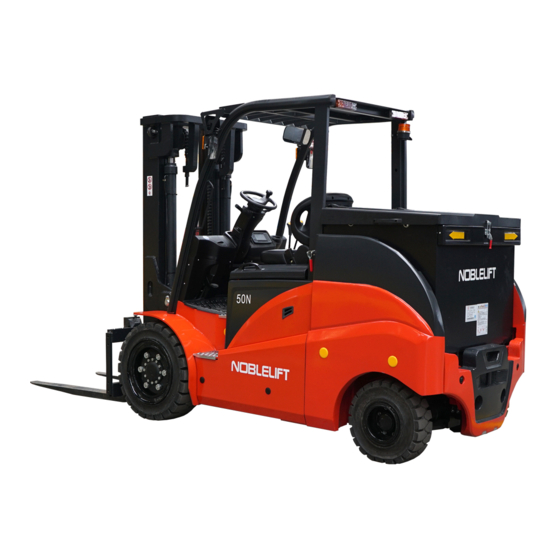
- Page 1 FE4P50-70N WARNING Do not use the pallet truck before reading and understanding these operating instructions. Keep for future reference. Operation and maintenance manual FE4P50-70 N series battery counter balanced forklift truck Noblelift Equipment Joint Stock Co., Ltd...
-
Page 2: Table Of Contents
Catalogue Forward ……………………………………………………………………………………………………… 4 Chapter one Attention when using the forklift truck ………………………………………………… 1、Transportation for forklift……………………………………………………………………………… 2、Deposit…………………………………………………………………………………………………… 5 3、Preparation before use………………………………………………………………………………… 4、Operation of truck……………………………………………………………………………………… 5、Battery charging………………………………………………………………………………………… 6 Chapter two The main performance parameters of forklift truck …………………………………… 7 Ⅰ、The truck’s outline dimension and performance parameters ……………………………………… 7 1.The truck’s outline dimension …………………………………………………………………………... - Page 3 5.Battery ………………………………………………………………………………………………… 40 5.1 Battery safety requirements ……………………………………………………………………… 5.2 Battery use requirements ………………………………………………………………………… ……… 5.3 Battery charging …………………………………………………………………………… Installation and replacement of battery …………………………………………………… 6.Hydraulic system …………………………………………………………………………………… 43 6.1 Sumarry ……………………………………………………………………………………………… 43 6.2 Oil pump ……………………………………………………………………………………………… 43 6.3 Multiway valve ……………………………………………………………………………………… 43 6.4 Lift cylinder and lift chains …………………………………………………………………………...
- Page 4 3.Switches ……………………………………………………………………………………………… 67 4.Control ………………………………………………………………………………………………… 68 5.Bodywork ……………………………………………………………………………………………… 70 Ⅲ、Safety issues…………………………………………………………………………………………… 72 1Operation place and working environment …………………………………………………………… 72 2.Safety rules …………………………………………………………………………………………… 72 3.Truck’ s transportation ………………………………………………………………………………… 82 4.Howtoavoidoverturning,howtoprotectyourself ……………………………………………………… 83 5. Safety problem in Maintenance ……………………………………………………………………… 84 6. Safety problem in battery usage ……………………………………………………………………… 86 7.Plate ……………………………………………………………………………………………………...
-
Page 5: Forward
Forward This manual briefly introduces the technical parameters as well as the construction,working principle and the requirements in operation and the maintenance of each main part of the four-wheel battery counter-balanced forklift truck of our company.Before operation,please read the manual carefully to ensure safe and efficient load portage by correct operation and maintenance,and to help the operator to use the battery forklift truck properly so as to make full use of it.It is hoped that the operator and the facility manager read the manual carefully before operation!Please perform strictly according to the attention matters in this manual,drive... -
Page 6: Chapter One Attention When Using The Forklift Truck
Chapter one Attentions when using the forklift truck The operator mast always keep in mind the principle of safety first.Conscientiously and cautiously read the maintenance manual.Undergo safe operate and canonical operate strictly following the demand in this manual 1 Transportation for forklift Pay attention to the following particulars when using container or automobile to convey forklift truck (1) Enable parking brake... -
Page 7: 5、Battery Charging
(11) No operation of truck and it’s additions without sitting on the driver’s seat (12) Push handle immediately to middle position when the mast has tilted forward or backward to the extreme position (13) No driving or turning when the mast is lifting (14) When travelling,pay attention to passers by,obstacles,irregular road and the clearance of upper side of forklift (15) Be careful of travelling on slope,when the angle of slope is more than10%,travel forward... -
Page 8: Chapter Two The Main Performance Parameters Of Forklift Truck
Chapter two The main performance parameters of forklift truck Ⅰ、The truck’s outline dimension and performance parameters 1. The truck’s outline dimension see figure 1-1 Figure 1-1 outline... - Page 10 2.2 FE4P50N Technical data(list 1-2) Model number FE4P50N Drive mode: Electromotion Operation mode: Seat-driving pattern Rated capacity Q(kg) 2500 Load center distance C(mm) Load distance x(mm) Wheelbase y(mm) 1500 Service weight including battery 4260 Axle loading,laden front/rear 6010/750 Axle loading,unladen front/rear kg...
- Page 11 2.3FE4P60-70N Technical data(list 1-3) Model number FE4P60N FE4P70N Drive mode: Electromotion Operation mode: Seat-driving pattern Rated capacity Q(kg) 3000 3500 Load center distance C(mm) Load distance x(mm) Wheelbase y(mm) 1650 1650 Service weight including battery 4850 5250 Axle loading,laden front/rear 6910/940 7700/1050 Axle loading,unladen front/rear kg...
-
Page 12: Ⅱ、The Construction,Principle And Adjustment Of The Truck's Main Parts
Ⅱ、The construction,principle and adjustment of the truck’s main parts 1. Drive system 1.1 Summarize The drive system consists of gear box assembly, differential mechanism assembly and drive axle, the reducer drive gear connects directly to drive motor.The travel speed increases with the increment of rotational speed of drive motor, And when the rotational direction of the motor changes, the travel direction changes too. -
Page 13: Drive Axle
1. differential 2.bearing seat 3.bolt 4.lock plate mechanism hub 5.gear 6.gear axle 7.washer 8.axle 9.gear 10. differential 11.gear ring 12.bolt mechanism hub 13.lock plate 14.bolt 15.lock washer 16.dowel pin 6×30 17.nut M10×1.25 18.bearing 6213 19.washer Figure 2-2 Differential mechanism 1.3 Drive axle The drive axle consists of axle shell,wheel hub and arrester. - Page 14 List 2-1) List 2-1The main technical parameter Truck model FE4P50N FE4P60N FE4P70N Construction pattern of drive front wheel drive,axle body is fixed with truck frame full...
-
Page 15: Installation Of Wheel Hub
1.4 Installation of wheel hub (1) Fill the wheel hub with 100ml grease,and then fix it on the axle.see figure 2-4. (2) Screw up adjust nuts with 9.8N.m of twist moment,then reverse them 1/2 coil (3) Hang the weighter on the bolt to measure the starting moment of the wheel hub,when it reachs the defined value,start to screw up the nut. -
Page 16: Malfunction Analysis
1.rim 2.rim 3.nut M16 4.washer 16 5.bolt 6.轮胎 figure 2-6 tyre assemble 1.5 Malfunction analysis List 2-2 malfunction diagnose and adjustment malfunction possible reason adjusting method items shake a lot the fastening bolts loosen Tighten gear oil deteriorates replacing Too high of Un usual Oil level Supplying or reducing temperature... -
Page 17: Brake Base Pump
1. brake oil cup 2. brake support 3. brake sensor 4. bolt 5. brake pedal 6. brake pump figure 2-7 brake paddle assembly 2.3 Brake base pump(figure 2-8) Base pump consists of a valve support,a one-way-valve,a rebound spring and base leather cup,piston,assistant leather cup.The end of the base pump is fixed with lock washer and lock steel wire,And the outside of it is protected with rubber dust preventing cover.The base pump works under the assistance of pushing rod by operating brake paddle,Step down the brake paddle,the... -
Page 18: Brake Staff
1.latch nut 2.pushing rod 3.antidust cover 4.locking steel wire 5.locking 6.assistant 7.piston 8.base leather washer leather cup 9.spring 10.cheak valve 11.valve 12.pump body supporter figure 2-8 base brake pump 2.4 Brake The brake staff adopted is two shoe brake installed in the two sides of drive axle.The brake staff consists of two groups of brake shoes,subsidiary brake pumps and regulators,one end of the brake shoe,which holds back the parking brake parts through rebound spring and Pressure spring,contacts with fixing pin and another end of it contacts with regulator,In addition,there are... - Page 19 (1) Motion of brake stuff The brake drum is pressed by the leading brake shoe and the secondary brake shoe with the same force from subsidiary brake pump,when the top side of the brake shoe is stopped by the fixed pin,the brake shoe will move toward brake drum until being stopped by the fixed pin,then the friction between wearing piece and brake drum will increase.
-
Page 20: Parking Brake Operating Device
2.5 Parking brake operating device(figure 2-15) Parking brake handle is cam in pattern.Adjuster lying at the end of handle is available to adjust the brake force. Turning the adjuster clockwisely,the brake force increases;Turning the adjuster counter clockwisely,the brake force decreases. Pulling force:196N~294N figure 2-14 gap-self-regulating device figure 2-15 parking brake handle... - Page 21 regulator and regulating spring.See figure 2-19 figure 2-18 figure 2-19 (5) Disassemble the brake tube from the driven brake pump,and disassemble the assembling bolts on the subsidiary brake pump.Then disassemble the subsidiary brake pump from brake device motherboard.See figure 2-20 (6) Disassemble the E baffle ring to fast the brake dragline from brake device motherboard.Then disassemble brake device motherboard bolts,and disassemble brake device motherboard from drive axle.
- Page 22 figure 2-23 figure 2-24 2.6.3 Assembling brake device (1) Wipe brake liquid on cup leather and piston of brake sub-pump, assembling spring, piston cup leather, piston and defend ring. (2) Install brake sub-pump on motherboard. (3) Mount motherboard on drive axle. (4) Wipe anti-heat lubricate grease on the region instructed in figure 2-25.
-
Page 23: Adjusting For Brake Pedal
figure 2-28 figure 2-29 2.6.4 Operating trial for self-adjustor of clearance See figure 2-30 (1) Adjust diameter of brake hoof close to the regulation size first, rotate adjustor by pulling adjusting bar, when releasing hand, adjusting bar return original place but adjustor gear doesn’t rotate. -
Page 24: Malfunction And Cause
Bolt Push rod Pedal figure 2-31 (5) Adjusting brake switch as figure 2-32 (a) After adjusting brake pedal height,release lock nut of brake switch (b) Pull off plug to separate wire (c) Rotate switch to make clearance into A=1mm (d) To be sure when step pedal down, the light of brake shall be open. (e) Tighten the nut. -
Page 25: Maintenance
Brake badness Adjusting Mal-touching between brake drum and friction slice again 5 Dirt on friction slice Repair or replace 6 Impurity is in liquid Check brake liquid 7 Bad-regulate for brake pedal(inching valve) Regulate Repair or 1 Friction slice impurity or case hardening replace Repair or 2 Motherboard deformation or bolt loose... -
Page 26: 3.Steering System
(a) Check brake drum to see whether there is destructive abrasion. (b) Check brake shoe for abrasion,if it can not reach the operating requirement,replace the brake shoe at once. (c) Check whether the axle shell is normal,if the oil level is less than normal,supplement the ⑤... -
Page 27: Steering Axle
valve in valve body to be used to prevent damage on equipment when hydraulic pressure is too high produced by impact of outside force which is from ground to wheels during travelling. Both safety valve and two-way overloading valve are regulated in optimum by manufacturer, so, users shall not regulate it randomly. - Page 28 1.steering axle 2.connecting rod 3.steering cylinder 4.anti vibration pad assembly 5.steering axle fixing 6. right knuckle 7. bearing 51208 8.bearing 943/32 plate assembly 9.kingpin 10.dowel pin 10×20 11.adjusting pad 12.oil seal 13.kunckle adjusting 14.nut M12 15.dust cover 16. bearing 17. bearing 18.
- Page 29 (1) Kunckle Kunckle,combined by kunckle king pin,conical roller bearing,anti-dust cover,O ring,locates between upper and down side of the steering axle body terminals. the upper end of king pin is fastened on axle body by stop pin,and the lower end of it is fasten on axle body by forelock. The supporter is supported by conical roller bearing which is pressed-in the axle body.(see figure 2-36)...
-
Page 30: Gist For Adjustment And Maintenance
(3) Wheel hub Wheel Hub is fitted on kunckle by taper bearing, wheel is fitted on wheel hub by wheel rim, there is oil seal inside of bearing to keep lubricate greese in cavity of wheel hub and kunckle. There is nut to adjust bearing for elasticity. 3.4 Gist for adjustment and maintenance (1) See figure 2-38, lubricate inner cavity of wheel hub, inside or outside bearing and cover of wheel hub, meanwhile, lubricate oil seal... -
Page 31: Diagnose Of Steering System
3.6 Diagnose of steering system(list2-4) List 2-4 problem cause elimation damage or malfunction of oil pump replace steering wheel can not move hose connector is damaged or plug of pipeline replace or cleaning safety valve pressure is too low adjust pressure air in oil circuit exhaust air steering wheel... -
Page 32: 4.Electrical System
4. Electrical system 4.1 Summary Electrical system of FE4P50N is powered by 48V battery set, Electrical system of FE4P60-70N is powered by 80V battery set .traction power of the truck is powered by AC motor, lifting power is produced when AC motor is driving the oil pump to produce oil pressure. Lighting system is powered by battery 48V(80V) to 24V voltage. -
Page 33: Electrical System Of Direct Current Driving Electric Forklift Truck
4.2 Electrical system of direct current driving electric forklift truck (Fig.2-42) (Fig.2-42) 4.2.1 Forklift traction is AC variable-frequency motor, steering is AC variable-frequency motor controller, the dashboard display screen and AC drives adopes products from Curtis, the world's leading supplier of electric vehicle system in the United States. The adopted AC variable-frequency motor is high efficient, durable and maintenance free, basically because it has no DC motor commutator (commutator can limit the acceleration performance of truck, especially in high speed situation, it will limit braking torque), so its accelerating ability is faster. -
Page 34: Combination Indicator
brake can be achieved by properly releasing the accelerating pedal.The presenting back of electric power to battery prolongs the one-charge-travelling distance of it. 4、 Function of backward slip preventation on slope,when the vehicle is stopped on slope,it will slip downward the slop acceleratedly if hand brake or food brake pedal is released. The function of backward slip preventation can prevent the phenomenon of slipping downward acceleratedly and ensure that electric forklift slips downward uniformly with a low speed. - Page 35 Figure 2-44 CURTIS instrument 1) 、 “TRVAL”means the situation of traction controller, digital code indicates controller failure, specific code please refer to 4.4 failure analysis. 2) 、“HYD”means situation of pump controller, digital code indicates controller failure, specific code please refer to 4.4 failure analysis. 3)...
-
Page 36: Fault Analysis
4.4 Failure analysis 1232SE/1234SE Controller fault table and diagnostics guide Code Code display on display on Troubleshoot Fault cause the programmer instrument 1、motor outside U,V or Wconnection shour current Controller controllercurrentoverload Overcurrent 2、motor parameter mismatching 3、controller failure 1, motor U、 V、 W truck circuit, lead Current Sensor Current sensor failure to current leakage... - Page 37 large 5, battery connection is disconnected 6, the fuse is disconnected, or main contactor is not connected 1, during the process of regenerative braking, regenerative braking current lead the Voltage too high, as a battery voltage to rise Overvoltage result the performance is 2,...
- Page 38 1. connected load is open circuit or Drive 2 output linkng coil Coil2 Driver short circuit is open circuit or short Open/Short3.3 2. connecting pin is stained circuit 3. wrong wiring 1, connected load is open circuit Electromagnetic brake or short circuit EMBrake coil is open circuit or Open/Short...
- Page 39 1,The key start, interlock, direction, and the accelerator input HPD/Sequencing High pedal protection order is wrongly setted. Fault /operation order failure 2, Wiring, switch key, interlock, direction, or accelerator input failure 1,Emergency reverse operation is Emergenvy reverse high over, but the forward, reverse input Emer Rev HPD pedal protection and interlock of the accelerator are...
- Page 40 8= Controller cannot detect the encoder signal, channel signals disappears 9= Motor parameter settings exceed the scope 1,motor type(Motor_Type) Motor Type Fault Motor type failure parameters exceed the scope 1,VCL and OS of the controller VLC/OS Mismatch VCL/OS not matched program are not matching 1,...
-
Page 41: 5.Battery
5.Battery Battery framework see figure 2-45. figure2-45 battery 5.1 Battery safety requirements Good ventilation is necessary. Because hydrogen and oxygen take place at the later △ period of charging battery, so, sparks will lead to explosion. There is acid mist taking place during charging,please exhaust it and cleaning battery △... -
Page 42: Battery Charging
Rub-up dust of battery by cloth, if there is electrolyte stains, rub-up or cleanse by hot water, then dry it by cloth. Clean dirt and oxide of pole, rub-up lead and lead clip. Dredge venthole of oil inlet. Apply a thin industrial Vaseline on pole and lead clip. Check battery for liquid level. - Page 43 Warning: Slowly infuse strong sulphuric acid into distill water and stir liquid by a glass rod or lead cover wood stick, do not infuse distill water into sulphuric acid absolutely, otherwise, there will be liquid boiling and splashing to injure people. To be sure the polarity of connection between charger and battery is correct, that is anode to anode and cathode to cathode,a reliable connection is necessary.
-
Page 44: Installation And Replacement Of Battery
5.4 Installation and replacement of battery Battery installation shall fix fastened, prohibit to overturn; Prohibit to hammer terminal and leading clips; Avoid impact during transporting. 6. Hydraulic system 6.1 Sumarry Hydraulic system consists of pump, multiway valve, lift cylinder, tilt cylinder and pipeline ect. See figure 2-46,Hyduaulic liquid supplied by pump and multiway valve distribute liquid to each cylinder. - Page 45 1. Safety valve 2. Inching switch support 3. Spill pore 4. Lift timing sensor cover figure 2-47 Multiway valve outline (1) Operation of Slide valve (To tilting slide valve,for example) (a) Neutral (figure 2-50) In this case,high pressure liquid out of pump to tank through neutral (b) Push slide valve in (figure 2-51) Then, neutral chunnel is closed, liquid from oil inlet to open one-way valve flow to cylinder joint B, liquid from cylinder joint A flow to tank through low pressure chunnel, supported by...
- Page 46 Figure 2-52 (3) Motion of tilting self-locked valve There is tilting self-locked valve in tilting cylinder valve slice to prevent mast fall down suddenly when cylinder cavity take place negative pressure and danger when mal-operating tilting valve stick. Because this self-locked valve, if even thrusting joy stick, mast cannot be tilted when forklift motor stop work.
-
Page 47: Lift Cylinder And Lift Chains
1. tilting rod operation 2. lifting rod operation 3. accessary rod operation 4. connecting shaft 5. connecting rod 6. bracket figure2-55 multiway operation (5) adjust safety valve pressure Adjusted pressure for safety is 13.5/16.8MPa Safety pressure had been set it up by manufacturer, user shall not be setup by themself. - Page 48 left lifting cylinder right lifting cylinder 1. anti-dust ring 2. axes seal 3.steel cap 1. O-ring 5.bearing 6.cylinder 7.piston rod 8.adjusting 9.O ring 10.spring bushing 11. circlip 12.spring 13.piston 14.support ring 15.valve seat core 16.circlip 17.hole seal 18.check 19.circlip 20.valve valve 21.O ring 22.speed...
-
Page 49: Tilt Cylinder
Normal cylinder Cut off 1.lifting cylinder body 2.pressure spring 3.valve core figure 2-57 isolating valve 6.5 tilt cylinder Ttilting cylinder,whose piston rod connects to mast through earbob,is double-acting in pattern. The bottom of tilting cylinder connects to framework with pin. There are two tilting cylinders on each side of forklift. - Page 50 1.cylinder 2.respirator 3.cylinder 4.cylinder flap 5.seal pad 6.filter 7.washer 8.drain plug Figure 2-60 6.7 Hydraulic oil pipeline Hydraulic system hydraulic oil pipelice. See figure 2-61。 1. joint 25-G1-Φ32 2. rubber hose (oil suction) 3. Hose clamp QC/T390-(40-45) 4.Hose clamp QC/T390-(22-26) 5.
-
Page 51: Hydraulic Hose
9. joint 8-2xM16x1.5-60° 10. hydraulic hose assembly 8-L2700-1SC-60° 11. hydraulic hose assembly 8-L3000-1SC-60° 12. hydraulic hose assembly (90°)13-L2750-2SC-60° 13. joint 12-G1/2-M22x1.5-60° 14. transition pipe welding 15. washer GB97.1-6-200HV 16. washer GB93-6 17. screw GB70.1-M6x20-8.8 18. joint 16-M22x1.5-%c25 19. rubber hose 20. - Page 52 lining board groove oil-in side of inlet port side of outlet port oil-out Figure 2-64 Figure 2-65 (c) Front and behind pupm cover If colour changing(brown)extent of inner surface lining sleeve is more than 150°, please replace it. (d) Check drive wheel and driven gears If abrasion badly, to replace a pair.
-
Page 53: Fault Analysis
1. pump body 2. drive gear 3. driven gear 4. front end cover 5. rear end cover 6. lining slice 7. seal 8.spacer ring 9. oil seal 10. elastic collar 11. bolt 12. washer Figure 2-67 gear pump (4) Commissioning Commissioning includes running in pump by commissioning, checking running for normal, it is better to test pump on test-bed, but testing at forklift also to be available as follows: (if pump abrasion badly or locking attributed to hydraulic liquid and being disassembled, you... - Page 54 Fault Cause Elimination Slide valve get stuck Break up, cleaning Lift pressure too low Oil pore jam Break up, cleaning Slide valve get stuck Break up, cleaning Vibration Pressure up too slowly Exhaust not enough Exhaust enough Slide valve get stuck Break up, cleaning Vibration Pressure up too slowly...
-
Page 55: 7.Lifting System
7. Lifting system 7.1 Summarize Lift system consist of dual mast (inner and outer mast respectively), roller lift and lower vertically, and fork. 7.2 Inner and outer mast (figure 2-68) inner and outer mast constructed by welding. Bottom of outer mast fit on drive axle by brace. Middle of outer mast connect with frame through tilting cylinder and it can tilt forward and backward actuated by tilting cylinder. -
Page 56: Roller Position
1. load guard 2. plain washer 3. spring washer 4. bolt 5. roller 6. elastic collar for axes 7. combination roller 8. fork carriage 9. fork assembly Figure 2-69 fork carrier 7.4 Roller position (figure 2-70) There are two rollers: outer frame roller unit as well as inner frame and fork carriage roller unit, witch is fitted on outer mast as well as inner mast and fork carriage respectively. -
Page 57: Maintenanceandregulation
1. Fork carriage 2. Outer mast 3. Outer frame roller unit 4. Inner mast 5. Inner frame and fork carriage roller unit figure 2-70 Roller position Notice: (a) Adjust clearance of side roller for 0.5mm; (b) Lubricate grease on main roller surface and working surface of mast. 7.5 Maintenance and regulation 7.5.1 Adjustment of lift cylinder See figure 2-71 It is needed to readjust journey of lift cylinder after dismantle or replace lift cylinder, inner mast... - Page 58 Inner mast Tyre fork carriage main roller fork Figure 2-72 (3) Lowering fork on ground and tilting it backward at max. angle. Keep both of two chains be same tension by adjusting nut which locate upper end of adjust chain. 7.5.3 Replacement of fork carriage roller (1) Place a pallet on fork and park forklift on level ground.
-
Page 59: Instructionsofinstallingaccessaries
8.2 Hoisting location for parts disassembled (1) Hoisting directions for lifting system see figure 2-75 outline dimension figure 2-75 Type Weight (kg) length×width×height(mm) FE4P50N 2000×1080×463 FE4P60-70N 2050×1180×485 (2) Roof guard hoisting directions see figure 2-76 outline dimension Type Weight(kg)... - Page 60 FE4P50N 480×1135×1000 FE4P60N 520×1135×1000 1250 FE4P70N 560×1135×1000 1650 (4) Hoisting for battery box See figure 2-78 outline dimension Weight Type length×width×height(mm) (kg) Lifting hole FE4P50N 980×538×760 FE4P60-70N 980×688×760 1530 figure 2-78 Battery has the function of counterweight,so users can not replace it at will otherwise it will affect the balance of entire vehicle and other performances.
-
Page 61: Chapter Three Operation,Use And Safety For Forklift
Chapter three Operation,use and safety for forklift Ⅰ、 Driving and operation There are some information for operating normally as below and it favor you about good running performance, using safely, running economically. 1. Usage of new vehicle ·All of the parking parts from the new vehicle should be reclaimed according to the establishment of local government. -
Page 62: 5.Transportingandloadingforforklift
backrest or rigidity loading goods frame, or low lift height. 5. Transporting and loading for forklift (1) Transportation of forklift ·Transporting with truck,Wedge forklift wheel or tighten forklift by rope to prevent it moving during transportation. ·Pay attention to obey regulation of full-length, full-width, full-height of forklift during transportation on traffic road. -
Page 63: 8.Parking And Temporary Parking
·Do not startup or brake suddenly to prevent cargo falling down . (2) Speed slow down Release accelerator slowly. If necessary, step brake pedal down. Except emergency brake, release accelerator to make slow down slowly until parking. If even release accelerator suddenly, emergency brake is also impossible. -
Page 64: 9.Usage Of Battery
cloth on fork prong forward dead corner. ·Pay attention for road surface slide or cave in. ·To lower fork after parking perfectly, it is very dangerous to lower fork during traveling. ·Do not jump off vehicle. ·When get off forklift, you have to face vehicle and take favour of footboard. ·Slow down first and step brake pedal down and standstill and put gearshift on “N”. -
Page 65: 10.Stacking
·According to 《operation and maintenance manual》of the used charger to break charging procedure. ·Do not pull out charger plug during charging, otherwise there will be spark take place to lead to danger. (2) Replace bettery When forklift has been used continuously for a working period and the battery has entirely excharged,replace the battery with another fully charged one and charge the battery been replaced. -
Page 66: 11.Unstacking
(b) Backing forklift for distance of 1/4 length of fork. (c) Lift fork 50—100mm up and drive forklift forward for stacking to be optimum. (8) Look at rear space, backing forklift in order to avoid impact between fork and pallet or goods. (9) Ensure fork prong to be off goods or pallet, lower fork to avail driving.(from ground 150—200mm) 11.... -
Page 67: Ⅱ、Using Instruction Ofoperatingdevices
(c) Rub anticonosive oil on bared surface of piston rod and shaft ect. (d) Cover parts prevent raining and wet. (e) Startup vehicle at least once a month, install battery, clean the grease on piston and shaft, startup engine and preheating, make vehicle move forward and backward slowly, meanwhile operating hydraulic control for several times. -
Page 68: 1. Components,Schematicdiagramforoperatingdevices
2. Instrument unit see figure 2.4 Electrical system( page 30) 。 3. Switches (1)Emergency stop button When emergency, press red mushroom-head button down to cut off power to stop function of traveling, turning, lifting. To resume the function,rotate the botton according to the arrowhead indication. (2)Key switch key can turn on or turn off controlling power Turn off (0FF): In this position,power is cut off and key can be inserted... -
Page 69: 4.Control
Tail light switch is a single gear which controls on&off of the light. Pull switch up, light open; push down, light off. 4. Control Ssteering wheel①and steering wheel handlebar② Steering wheel operation is traditional: steering wheel turn right, vehicle move right; steering wheel turn left,vehicle move left.There is steering wheel at backside of forklift to make backside of forklift swing toward outside when turning. - Page 70 (4) Parking brake handle⑥ In order to prevent forklift from moving,when park forklift,pull up entirely parking brake handle. It is necessary to push parking brake handle to end before driving. ·When operating the parking barke handle,step down the parking paddle. (5) Brake paddle⑦and accelerating paddle⑧...
-
Page 71: 5.Bodywork
(6) Lifting handle⑨ Pull backward lifting handle,fork lifts,and push forward lifting handle,fork lowers.lifting and lowering speed depend on tilting angle of handle,the larger the angle,the faster the speed is. ·Lifting operation cann’t be made,if push or pull lifting handle when turn on ignition key. ·Don’t lower fork suddenly or stop suddenly when lowering fork. - Page 72 (4) Traction rod Only in the following situation shall be possible to use traction rod. ·To escape from the trouble of being not able to travel(for example wheel trapped in ditch) ·Forklift need to be loaded on or be unloaded from lorry. ·No using for towing or to be towed operation absolutely.
-
Page 73: Ⅲ、Safety Issues
Ⅲ、Safety issues Safety is your business and responsibility. This section describes the typical forklift often used in the basic safety regulations and warnings, but also applies to the door frame with special specifications. 1 Operation place and working environment (1) Ground conditions The operation place of forklift should be ground with flat and firm surface,a good ventilation is needed. - Page 74 Vigilant: injuries, the ambulance! Do not change parts on forklift arbitrary Read the instruction manual carefully before without permission. driving! Turn off the engine before maintenance! Understand traffic regulations Before use, please check on the truck! Do not move the overhead guard!
- Page 75 To keep driver’s cap clean! Do not drive an unsafe forklift! Drivers should have a healthy body! Be sure your truck is safe! Work in specified area Do not drive a damaged truck! Hold tightly when get on the truck! Start forklift correctly!
- Page 76 Adjust seat before driving! Make sure your forklift is in safe operating condition! Appropriate fasten seat belts! Always pay attention to the height of work place! Turn on lights in dark area! Do not put arm and body outside of the overhead guard during work! Avoid driving on soft ground, only Keep body under the guards!
- Page 77 Avoid eccentric loading! Pay attention to encounter item by front fork when loading! Check fork pin position! Note the security of the work region! Do not run on smooth or slippery ground! Note the horizontal driving stability of the truck when it is un-load! Be especially careful when handling long Forbid handling people!
- Page 78 or wide cargo! If can not see the front when turning, Use appropriate pallets or sleeper when please whistle and drive slowly. handling small objects! Do not chase each other through the traffic! Not allowed to stand on the goods! Not allowed to gaze around while driving! Do not use the forklift to do stunt! when goods is so high to keep out line...
- Page 79 direction of others when loading,travel forward in upgrade Pay attention to the steep uphill slopes and backward in downgrade and goods lifting height! When no-load,travel backward in upgrade Note using brake when start truck on and travel forward in downgrade! the slopes! Not turn when driving on a slope! People or things moving on road should...
- Page 80 While turning a high speed can cause People are not allowed to start in work place! accident because of unstable center of gravity! Notice the change of rated load weight Pay attention to the area where forklift before use forklift. is driven! Use the fork correctly when loading! Slow down when loading!
- Page 81 someone in front of the truck! the elevatory fork! Do not load the goods which is higher Please bind the goods which is difficult than the goods rest. to fix before load! Do not carry the goods from forklift by Do not let people to carry the goods have manpower! been damaged!
- Page 82 Do not extend any part of body outside Drive the truck smoothly to avoid sudden when driving! acceleration and deceleration! Must use special equipment to lift people Do not overload! safely to lift people safely to work at height! Do not lift when there is excessive wind! Not allowed to work in explosive environments! The faulty trucks should be put into the park the forklift to the indicated area!
-
Page 83: 3.Truck' S Transportation
Do not park the forklift on the slope! When the forklift is not in use,please do the follow. — Brake — Put direction pole in neutral position. — Lower the fork to the ground — Frame forward tilt. — Take off the key 3. -
Page 84: 4.Howtoavoidoverturning,Howtoprotectyourself
·When lifting the truck, be sure not to wire rope and overhead guard around together. ·Wire rope and lifting equipment to be very strong, enough to secure bearing fork lift, because the truck is extremely heavy. ·Do not use the cab (overhead guard) to hoist the forklift. ·Forklift upgrade, do not enter the truck underneath. -
Page 85: Safety Problem In Maintenance
When moving, the distance between fork and whether load or no-load,don’t turn in a high ground should less than 150mm to 200mm! speed or in a large radian ! when no-load fork is lifted,please turn with Be sure to fasten seat belts! a narrow range. - Page 86 (2) Precautions before maintenance ·No smoking ·Wear all protective equipment (helmets, shoes, glasses, gloves and boots), and suitable clothing. ·Wipe out the oil in time. ·When add lubricating oil, you should clean out dirty oil or dust with a brush or cloth, then add oil.
-
Page 87: 6. Safety Problem In Battery Usage
6. Safety problem in battery usage (1) No smoking ·Batteries produce hydrogen gas. Short circuit will produce sparks when lit cigarette near the battery, it will cause an explosion and fire. (2) Avoid electrical attack · Battery with high voltage, when the installation and maintenance, do not touch the battery conductor, which can cause serious burns. -
Page 88: 7.Plate
(8) Battery electrolyte is harmful ·Battery electrolyte is made of diluted sulfuric acid, be careful when handling. ·When electrolyte adhesion conglytination on eyes, skin and clothing, it will result in vision loss and burns. (9) Emergency dealing methods ·When the accident occurred, deal according to the following methods of emergency treatment and contact a doctor immediately. - Page 89 Left safety mark Right safety mark Usage of forklift Forklift nameplate Lubrication system signs Load graph signs Add hydraulic oil signs hoisting signs prohibiting hoisting signs...
- Page 90 Truck hoisting signs Prohibiting climbing signs Handbrake signs Tyre pressure signs Tyre removal signs Note signs of injury...
-
Page 91: Chapter Four Truck's Regular Check And Maintenance
Chapter four Truck’s regular check and maintenance Conduct a comprehensive pre-inspection of forklift trucks and forklifts to avoid failure and fail to produce the life it deserves. Maintenance program is based on the number of hours listed in forklift work 8 hours a day, working 200 hours a month the case may be, in order to maintain safe operation and maintenance procedures should be maintained on the forklift. -
Page 92: Checking Procedure
2. Checking procedure (1) Check the brake pedal Check brake condition and to ensure a fully depresses the brake pedal when the plane from the floor counting down the brake pedal travel should be more than 50mm, no-load forklift truck braking distance about 2.5m. - Page 93 (4) Check the steering wheel rotation case The steering wheel clockwise and counterclockwise rotating gently, check whether there is rebound phenomenon, a suitable spring trip to 50-100mm. Steering wheel before and after the trips of about 7 °, if the above situation, turn the steering wheel shall be normal. (5) Check the function of steering system The steering wheel clockwise and counterclockwise rotation, check the power steering work.
- Page 94 (10) Check tires (pneumatic tires) Unplug the nozzle cap, measuring tire pressure with a tire air pressure. After check air pressure, nozzle mouth should ensure that gas will not leak before installed the cap. ·Forklift tire pressure is higher than the car’s; it should not exceed the prescribed pressure value.
- Page 95 Check whether the normal bright lights, speakers is normal (when pressing the horn button, horn ring) Check whether the emergency stop is normal. left steering light is bright neutral right steering light is bright (14) Check instrument panel features Normally, after a few seconds turn the key switch, the dashboard will be the following graph shows Tips locking...
-
Page 96: Ⅱ、Check After Operation
In addition to checking lights and operating conditions, the key switch must be turned off and disconnect the battery plug before check the electrical system. Ⅱ、Check after operation After the completion of the work remove the dirt on forklift and check the forklift according to the follow items:... -
Page 97: Ⅳ、Regular Maintenance
·If moisture penetration into the motor, you must first remove the moisture, to prevent short circuits Moisture will reduce brake performance, brake truck briefly to drying the brake. After cleaning Ⅳ、 ·Thoroughly dry water stains on the truck (use compressed air as a example). ·Start the forklift according to the procedures. - Page 98 At the Check if the malfunction begin- analysis system is normal ning of 2 years (3)Motor Every- Every Every Three Maintena- Maintenance item Tools week month months months nce item (8h) (50h) (200h) (600h) (1200h) Remove the eyewinker from √ √...
- Page 99 Every- Every Every Three Maintena- Maintenance item Tools week month months months nce item (8h) (50h) (200h) (600h) (1200h) Check clearance √ √ √ √ √ Check axis loose √ √ √ √ √ Steering wheel Check radial losse √ √...
- Page 100 Wear of reduction gearbox √ √ connectors Damage, leakage, rupture √ √ √ pipe Loose situation of connection and clamping √ √ √ parts Leakage situation √ √ √ √ √ Check oil level, √ √ √ × oil changing. Brake Pump situation √...
- Page 101 Check the chain tension state, whether deformation, √ √ √ √ √ corrosion damage Fuel chain √ √ √ Chain and Rivet pin and loose √ √ √ chain wheel conditions Chain wheel deformation, √ √ √ damage If Bearings of chain wheel √...
-
Page 102: Regular Replacement Of Key Safety Parts
(8h) (50h) (200h) (600h) (1200h) Measur- Overhead Installation is firmly √ √ √ √ √ guard and hammer load Check the deformation, backrest √ √ √ √ √ cracking, damage Indicator light for Work and installations √ √ √ √ √... -
Page 103: Ⅴ、Area Lubricated And Lubricant Recommended
Ⅴ、Area lubricated and lubricant recommended 1. Area lubricated ○:Change FO: Hydraulic oil ○:reinforce GO: Gear oil □:Check and adjust CG: Grease BO: Brake fluid W: Distilled water Lifting chain CG Direction pipe column CG Tilt cylinder pin CG Battery □W Mast bearing support CG Drive axle □CG Brake cylinder BO... - Page 104 Maintenance record Date Maintenance content Noter...
- Page 105 Noblelift North America 2461 S. Wolf Road Des Plaines, IL 60018 T: 847-595-7100 F: 847-595-7200 parts@nobleliftna.com www.nobleliftna.com...