
Subscribe to Our Youtube Channel
Related Manuals for Beckhoff CP26 Series


Summary of Contents for Beckhoff CP26 Series
- Page 1 Installation and Operating instructions for CP26xx Multi-touch built-in Panel PC Version: 1.5 Date: 2023-09-28...
-
Page 3: Table Of Contents
Table of contents Table of contents 1 Foreword Notes on the Documentation 1.1.1 Liability Conditions 1.1.2 Trademarks 1.1.3 Patent Pending 1.1.4 Copyright 1.1.5 State at Delivery 1.1.6 Delivery conditions Description of safety symbols Basic safety measures Operator’s obligation to exercise diligence 1.4.1 National regulations 1.4.2... - Page 4 5 Troubleshooting 6 Assembly dimensions 7 Technical Data 8 Appendix Beckhoff Support and Service 8.1.1 Beckhoff branches and partner companies 8.1.2 Beckhoff company headquarters Approvals for USA and Canada FCC Approvals for the United States of America FCC Approval for Canada...
-
Page 5: Foreword
Modifications to hardware or software configurations other than those described in the documentation are not permitted, and nullify the liability of Beckhoff Automation GmbH. 1.1.6 Delivery conditions In addition, the general delivery conditions of the company Beckhoff Automation GmbH apply. CP26xx... -
Page 6: Description Of Safety Symbols
Foreword 1.2 Description of safety symbols The following safety symbols are used in this operating manual. They are intended to alert the reader to the associated safety instructions. Acute risk of injury! If you do not adhere the safety advise adjoining this symbol, there is immediate danger to life and health of individuals! DANGER Risk of injury! -
Page 7: Basic Safety Measures
Foreword 1.3 Basic safety measures Before the Panel PC is switched off, software that is running must be properly closed. Otherwise it is possible that data on the storage medium is lost. Please read the section Switching the Panel PC on and off. -
Page 8: Operator's Obligation To Exercise Diligence
• the operation manual is in good condition and complete, and always available for reference at the location of the product. Do not open the housing of the Panel PC! For technical support contact Beckhoff Service. Note 1.4.1 National regulations Depending on the type of machine and plant in which the Panel PC is used, national regulations governing the controllers of such machines will apply, and must be observed by the operator. -
Page 9: Product Description
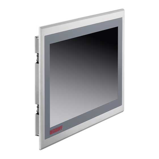
2.1 Product overview The compact multi-touch built-in Panel PC The new Beckhoff Panel PC generation with industry-standard multi-touch display offers a feature-laden solution for any application. The wide selection of models offers different display sizes and formats as well as custom designs. Even for single-touch users, this new Panel PC generation offers an excellent price-to-performance ratio and represents an economical alternative to other systems. -
Page 10: Appropriate Use
Product Description 2.2 Appropriate Use The multi-touch built-in Panel PC CP26xx is designed for industrial application in machine and plant engineering. A multi-touch display is accommodated in an aluminium housing. The Panel PC is installed in the front of control cabinets. Risk of explosion! The Panel PC must not be used where there is a risk of explosion. -
Page 11: Interfaces
Product Description 2.4 Interfaces X107 X104, X105 X102 X101 Ground COM1 LAN1 Power X103 EtherCAT 2.4.1 Power Supply (X101) The power supply for the Panel PC is established via the socket (X101). The power supply connector is included in delivery. Signal Signal Power Supply... -
Page 12: Access To The Battery And The Plug-In Card Slot
Product Description 2.5 Access to the battery and the plug-in card slot The battery and the plug-in card slot are located behind the cover plate beside the connectors of the Panel PC: screw (1) battery cover plate (2) MicroSD card For replacing the battery and installation of the Micro-SD card first unloose the cross-head screw (1). -
Page 13: 1-Second Ups
Compact Flash/CFast/MicroSD card. The 1- second UPS only works for a few seconds. The UPS can be controlled from the PLC with the function block FB_S_UPS_CB3011. More detailed information can be found in the Beckhoff Information System under the following link: https://infosys.beckhoff.com/english.php?content=../content/1033/tcplclib_tc2_sups/2220095883.html&id= CP26xx... -
Page 14: Installation
4. Please keep the associated paperwork. It contains important information for handling the unit. 5. Check the contents for visible shipping damage. If you notice any shipping damage or inconsistencies between the contents and your order, you should notify Beckhoff Service. CP26xx... -
Page 15: Installation In The Control Cabinet
Installation 3.2 Installation in the control cabinet The Panel PC CP26xx is designed for mounting in control cabinets in machine and plant engineering applications. The ambient conditions specified for operation must be observed (see chapter Technical Data). 3.2.1 Preparation of the control cabinet The control cabinet wall must be prepared with the required mounting opening according to the Panel PC’s dimensions (see chapter Assembly... -
Page 16: Mounting Of The Panel Pc
Installation 3.2.3 Mounting of the Panel PC The Panel PC is installed in the cabinet wall with clamping levers. For the cutout dimension of the Panel PC see chapter Technical Data, the wall thickness is between 1 mm and 5 mm. 1. -
Page 17: Fitting The Power Supply Cable
Installation 3.3 Fitting the power supply cable Fit the cables for the power supply of the Panel PC, using the included material for assembling the connectors: Material for assembling the connector Plug connector 5-pole Stain relief housing with lacing cord Conductive cross-section The connector is specified for 16 A and can lift conductive cross-sections until 1.5 mm Note... -
Page 18: Connecting The Panel Pc
Installation 3.4 Connecting the Panel PC The mains plug must be disconnected Please read the documentation for the external devices prior to connecting them! Attention During thunderstorms, plug connector must neither be inserted nor removed! When disconnecting a plug connector, always handle it at the plug. Do not pull the cable! 3.4.1 Connecting cables The connections are located at the bottom of the Panel PC and are documented in the chapter Interfaces. -
Page 19: Operating Instructions
Operating Instructions 4 Operating Instructions 4.1 Switching the Panel PC on and off 4.1.1 Switching on The Panel PC does not have its own mains power switch. As soon as the power supply is switched on the Panel PC is activated. 4.1.2 Shutting down and switching off Control software such as is typically used on Industrial PCs permits various users to be given different rights. -
Page 20: Servicing And Maintenance
Operating Instructions 4.3 Servicing and maintenance 4.3.1 Cleaning Disconnect power supply Switch off the device and all connected devices, and disconnect the device from the power supply. DANGER The device can be cleaned with a soft, damp cleaning cloth. Do not use any aggressive cleaning materials, thinners, scouring material or hard objects that could cause scratches. -
Page 21: Troubleshooting
No power supply to the Panel PC Check power supply cable Cable not connected Correctly connect cable Call Beckhoff Service Panel PC boots, software starts, but Cause of the fault is either in the Call the manufacturer of the control does not operate correctly... -
Page 22: Assembly Dimensions
6 Assembly dimensions For the assembly dimensions of the Panels PC please visit our homepage. Here you will find the actual drawings using the link: http://www.beckhoff.de/german/download/technical_drawings.htm Notice mounting orientation The assembly of the unit must take place with the orientation diagrammed here. -
Page 23: Technical Data
Technical Data 7 Technical Data Risk of explosion! Do not use the Panel PC in areas of explosive hazard! Danger Pixel errors Pixel errors in the TFT display are production-caused and represent no complaint- reason! Note Anomalies of the Touchscreen Anomalies of the touchscreen sensor are production-caused and represent no complaint-reason! Note... -
Page 24: Appendix
Please contact your Beckhoff branch office or partner company for local support and service on Beckhoff products! The contact addresses for your country can be found in the list of Beckhoff branches and partner companies: www.beckhoff.com. You will also find further documentation for Beckhoff components there. -
Page 25: Approvals For Usa And Canada
Appendix 8.2 Approvals for USA and Canada 8.3 FCC Approvals for the United States of America FCC: Federal Communications Commission Radio Frequency Interference Statement This equipment has been tested and found to comply with the limits for a Class A digital device, pursuant to Part 15 of the FCC Rules.
Need help?
Do you have a question about the CP26 Series and is the answer not in the manual?
Questions and answers