Advertisement
Quick Links
.
6,000
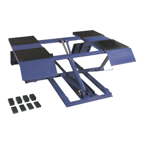
Easy frame lifting on padded runways. Great for wheel and brake work,
LB
tire and wheel changing as well as new car preparation.
L
-
OW
RISE
P
L
AD
IFT
6,000
.
Mid-rise models lift cars, vans and light-duty trucks. They are ideal for tire,
LB
wheel and brake related repairs, collision repair work and new car preparation.
M
-
L
ID
RISE
IFT
S
PECIFICATIONS
Lifting capacity
Overall width
Overall length
Maximum height
Low pad height
Lifting speed
Motor
Width between runways
Runway width
Collapsed height
Shipping weight
MR 6 K- 4 8
LR- 26 -PAD
6,000 lbs.
6,000 lbs.
73"
39
5
⁄
"- 57"
8
86"
96
1
⁄
"
2
26"- 30"
48
1
⁄
"- 54"
2
NA
7"
35 sec.
40 sec.
1hp/110 vac
1hp/110 vac
35"
NA
19"
NA
5"
4
3
⁄
"
4
955 lbs.
943 lbs.
Features:
6,000 lb. lifting capacity
Automatic safety locks
Low drive-over height
for approach of
low vehicles
High speed motor lifts
from 3"-26" in only
35 seconds
LR- 26 -PAD
2 sets of rubber
Low-rise
riser blocks
Pad lift
Features:
6,000 lb. lifting capacity
Portable trolley supports
pump and moves lift
Twin hydraulic cylinders
and scissors lift design
for maximum strength
MR 6 K- 4 8
Mid-rise lift
and stability
Easily adjustable sliding
radius arms
Automatic two-position
safety locks
Swivel pads come
standard. Optional
drop-in height adapters
are also available
Advertisement

Subscribe to Our Youtube Channel
Related Manuals for Tuxedo MR6K-48


Summary of Contents for Tuxedo MR6K-48
- Page 1 6,000 Easy frame lifting on padded runways. Great for wheel and brake work, tire and wheel changing as well as new car preparation. RISE Features: 6,000 lb. lifting capacity Automatic safety locks Low drive-over height for approach of low vehicles High speed motor lifts from 3”-26”...
- Page 2 MR6K-48 6000 lb Capacity Mid-Rise Scissor Lift ASSEMBLY & OPERATION MANUAL...
- Page 4 6,000 Easy frame lifting on padded runways. Great for wheel and brake work, tire and wheel changing as well as new car preparation. RISE Features: 6,000 lb. lifting capacity Automatic safety locks Low drive-over height for approach of low vehicles High speed motor lifts from 3”-26”...
- Page 5 There is no other express warranty on the Tuxedo lifts and this warranty is exclusive of and in lieu of all other warranties, expressed or implied, including all warranties of merchantability and fitness for a particular purpose.
-
Page 6: Product Specifications
PORTABLE MID-RISE SCISSOR LIFT INTRODUCTION MR6K-48 Portable Mid-rise Scissor Lift is a hydraulic lift, equipped with twin hydraulic cylinders for maximum strength and stability. It raises straight up without fore and aft movement. Low-profile, mid-rise and portable with rolling power cart, it is ideal for wheel and brake work, tire and wheel changing service with easy mobility. -
Page 7: General Safety Warnings And Precautions
SAVE THIS MANUAL: You will need this manual for the safety warning and precautions, assembly, operating, inspection, maintenance and cleaning procedures, parts list and assembly diagram. Keep your invoice with this manual. Write the invoice number on the inside of the front cover. Keep this manual and invoice in a safe and dry place for future reference. - Page 8 clothing, and gloves away from moving parts. Loose clothes, jewelry, or long hair can be caught in moving parts. AVOID ACCIDENTAL STARTING. BE SURE THE POWER SWITCH IS OFF BEFORE PLUGGING IN. KEEP HANDS AND FEET CLEAR. Remove hands and feet from any moving parts. Keep feet clear of lift when lowering. Avoid pinch points.
- Page 9 operate damaged equipment. Tag the damaged equipment “Do not use” until repaired. CHECK FOR MISALIGNMENT OR BINDING OF MOVING PARTS, BREAKAGE OF PARTS, AND ANY OTHER CONDITION THAT MAY AFFECT THE EQUIPMENT’S OPERATION. IF DAMAGED, HAVE THE EQUIPMENT SERVICED BEFORE OPERATION. Many accidents are caused by poorly maintained equipment.
- Page 10 Double insulated tools are equipped with a polarized plug (one blade is wider than the other). This plug will fit in a polarized outlet only one way. If the plug does not fit fully in the outlet, reverse the plug. If it still does not fit. Contact a qualified electrician to install a polarized outlet.
- Page 11 Make sure you know the weight of the vehicle you are going to lift before using the Lift. Do not exceed the maximum lift capacity (6000 pounds) for the Lift. Overloading the Lift could cause personal injury and / or property damage. Be aware of dynamic loading! If a weight suddenly falls onto the Lift.
- Page 12 allow at least two seconds after the Motor starts to raise or lower the Lift. Failure to do so may cause the Motor to burn out. PRIOR TO BEGINNING A JOB, MAKE SURE THE SAFETY LOCK ASSEMBLY (36B) AND ITS SAFETY CATCHES ARE IN THE PROPER POSITION. Never work underneath a vehicle without using additional safety support devices to support the vehicle.
- Page 13 UNTIL THE RUBBER SADDLES SECURELY CONTACT THE VEHICLE’S LIFTING POINTS. Then, lift the vehicle to the desired working height. Always lift the vehicle high enough for the Safety Lock Assembly (36B) to operate properly. DO NOT USE THE LIFT AS A PERMANENT STAND FOR A VEHICLE. Use the Lift only while making repairs.
- Page 14 ASSEMBLY INSTRUCTIONS DETERMINE THE PROPER LIFT LOCATION: DO not use the Lift on any asphalt surface. Make sure the Lift is used on a dry, oil/ grease free, flat, level, concrete surface capable of supporting the weight of the Lift. Do not use the Lift on concrete expansion seams or on cracked, defective concrete.
- Page 15 Cap on the Oil Tank. Add a premium quality hydraulic oil until the level of the oil is even with the Oil Tank's fill hole. Then, replace the Oil Tank Fill Cap. Before the first use and before all subsequent uses, check the hydraulic oil tank to make sure the Oil Tank is properly filled.
- Page 16 (13B) lower the Lift fully to the floor. NOTE: When working properly, you must BOTH squeeze in and hold the Brake Lever and press in and hold the Pressure Relief Valve Handle to lower the Lift. POSITION, LIFT AND LOWER A VEHICLE ON THE LIFT: Before driving a vehicle onto the Lift make sure that the Lift is fully lowered, and position the Plates (42B) and Rubber Saddles (39B) inward.
- Page 17 Once the repair work to the vehicle is completed make sure to remove all tools, safety jack stands, and materials form under the vehicle and Lift. Also, make sure the work area is clear and it is safe to lower the vehicle. To lower the Lift, use the POWER SWITCH and raise the vehicle slightly to take weight off the Safety Lock Assembly, and then release pressure.
-
Page 18: Inspection, Maintenance, And Cleaning
INSPECTION, MAINTENANCE, AND CLEANING WARNING! Always unplug the Power Cord from its electrical outlet before performing any inspection, adjustments, maintenance, or cleaning. BEFORE EACH USE, inspect the general condition of the Lift. Check for loose screws, misalignment or binding of moving parts, checked or broken parts, damaged electrical wiring and hoses, and any other condition that may affect its safe operation. -
Page 19: Troubleshooting Guide
TROUBLE-SHOOTING GUIDE PROBLEM CAUSE SOLUTION Replace the cable, the end of No power supply wire or fuse box The voltage is incorrect Apply the correct voltage Motor dose not run The operate button damaged Replace the operate button Motor windings burned out Replace Motor Change Motor rotation by Motor runs in reverse rotation... - Page 20 MR6K-48 Kernel Edtion 1.0 Mar.2008 Spare Parts List ITEM DESCRIPTION ITEM DESCRIPTION Table Scissor inside Retaining ring Wheel pin Locking nut Big wheel Oil pipe connector Small wheel Branch inlet pipe Wheel pin Oil pipe connector Conecion pin Oil supply fitting...
- Page 21 MR6K-48 Kernel Edtion 1.0 Mar.2008 Spare Parts List ITEM DESCRIPTION ITEM DESCRIPTION ITEM DESCRIPTION Lock wheel Lock sheath Spring Washer Lock block Bolt Bolt Lock pole Steel wire cable Check valve * Easily Worn Parts Page 2 of 2...
- Page 23 IMPORTANT POWER UNIT PRIMING PROCEDURE THE PROBLEM: Power unit runs fine but will not pump any fluid. Step 1 – Locate the check valve, the flush plug to the left of the lowering valve. (See drawing below.) Step 2 – Using an Allen wrench and shop towel – with shop towel in place to catch fluid –...
Need help?
Do you have a question about the MR6K-48 and is the answer not in the manual?
Questions and answers