ITRON 500W ERT Remote Installation Manual
Hide thumbs
Also See for 500W ERT:
- Installation manual (45 pages) ,
- Installation manual (50 pages) ,
- Installation manual (48 pages)

Related Manuals for ITRON 500W ERT


Summary of Contents for ITRON 500W ERT
- Page 1 500W ERT Module ® Remote Installation Guide Includes OpenWay Riva ® and Gen™X Network Information ITRON INSTALLATION GUIDE 30 June 2021 815-0005-00 REV 008 Itron, Inc. Page 1 of 45...
- Page 2 All other product names and logos in this documentation are used for identification purposes only and may be trademarks or registered trademarks of their respective companies. For more information about Itron or Itron products, go to www.itron.com. If you have questions or comments about a software or hardware product, contact Itron Technical Support Services. Contact Email: support@itron.com...
- Page 3 About the 500W ERT Module OpenWay® Riva Gen™5 Description Related Documents Itron Security Manager (ISM) Battery Life Low Battery Transmission Modes Mobile Mode Network Mode Operating Modes Firmware Functionality OpenWay Riva 30 June 2021 815-0005-00 REV 008 Itron, Inc. Page 3 of 45...
-
Page 4: Table Of Contents
Direct-mounting to the Meter Register Direct-mounting on the ABB Scancoder, InVision, or Digital Direct-Mount Direct-mounting to a Badger Direct-Mount Register Completing Gel-cap Connections Using the Itron Splice Kit Required Materials Using the Itron Cable Armor Installing the Itron Cable Armor... - Page 5 March 2020 ■ Added GSR 5.1 compatibility information to Firmware Functionality on page 13 January 2020 ■ Added Australia, ACMA Spectrum Compliance on page 7 July 2019 First publication. 30 June 2021 815-0005-00 REV 008 Itron, Inc. Page 5 of 45...
- Page 6 To ensure system performance, this device and antenna shall not be changed or modified without the express approval of Itron. Per FCC and ISED rules, unapproved modifications or operation beyond or in conflict with these instructions for use could void the user's authority to operate the equipment.
- Page 7 500W ERT Module Remote Installation Guide 1 Important Safety and Compliance Information Canada, ISED Spectrum Compliance Compliance Statement Canada Déclaration de Conformité This device complies with Innovation, Science and Le présent appareil est conforme aux CNR d'Industrie Economic Development Canada (ISED) license- Canada applicables aux appareils radio exempts de exempt RSS standard(s).
- Page 8 Itron device. Do Not Drop Warning! While Itron modules are designed to withstand a drop, dropping the module may damage the device and void the warranty. 30 June 2021 815-0005-00 REV 008 Itron, Inc.
- Page 9 Water Module. The UI associated with this device may reflect the former name. Gen™5 Itron Gen5 500W ERT modules are radio-frequency (RF) water modules that connect to the Gen5 Network as a leaf on a continuously powered device (CPD). The modules choose one CPD as a gateway to the Gen5 network.
- Page 10 ■ Authentication. Authentication is the process of confirming that an artifact is genuine or valid. Authentication in the 500W ERT module is the process of verifying a request is from a valid source and in its original form. ■...
- Page 11 Firmware Functionality on page Transmission Modes The 500W ERT module is an IPv6 Wisun compliant device that operates in Mobile Mode or Network Mode. Mobile Mode In Mobile Mode, the module transmits every nine seconds over multiple RF channels to report ■...
- Page 12 Caution: If you perform a Switch to Network Mode or Switch to Mobile Mode operation, it results in a loss of interval data. The 500W ERT module operates using the 902 to 928 MHz in the ISM band frequency band and does not require an FCC license.
- Page 13 If a remote 500W ERT module installed in quiet mode is not bubbling up SCM+ messages, it may be due to zero consumption on the remote 500W ERT module , such as a vacant or vacation home. Initiate a two-way command (for example, perform a Read ERT with FDM) before removing the unit.
-
Page 14: Genx
■ GSR 5.1 compatibility Firmware: 8.8.4.0 Encoder Image: 3.1.9.0 GenX This section lists the GenX 500W ERT module firmware information and lists functionality by version. Note: Each new version contains the features associated with the previous GSR. Table 1 GenX firmware details Part number... -
Page 15: Events And Alarms
(self-discharge) of the 500W ERT module . The low battery warning allows the utility to easily identify which 500W ERT modules are nearing end-of-life in a mixed population and gives the utility the opportunity to schedule replacement. - Page 16 500W ERT Module Remote Installation Guide 2 About the 500W ERT Module ■ Reverse flow ■ Zero consumption ® For more information about the extended alarms, see the OpenWay Collection Manager Device Interface Guide. 30 June 2021 815-0005-00 REV 008 Itron, Inc. Page 16 of 45...
-
Page 17: Initializing And Connecting
Itron Mobile Radio (IMR) connected to a user-supplied computer or Bluetooth device For normal activation, connect the remote 500W ERT module to the water meter register. The module polls for a register every hour and automatically activates after it detects a register. -
Page 18: Encoder-Type Register Connections
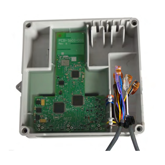
Do not place the programmer antenna directly on the remote module. Encoder-type Register Connections Connect the wires from the 500W ERT remote module to the register screw terminals according to the following table. Note: Itron recommends 19-26 gauge, pre-bonded or solid conductor wire with a maximum diameter of .082"... - Page 19 500W ERT Module Remote Installation Guide 3 Initializing and Connecting Remote 500W ERT module wire color Brown (data) Gray Yellow (ground) (power/clock) Register manufacturer Register screw color designator Elster AMCO evoQ4 Mag White Black Itron (Actaris) Cyble Coder Green Black...
-
Page 20: Pulser-Type Register Connections
Order the 25-foot inline connector extension cable assembly (CFG-0151-404) to extend the cable of the 500W ERT module . Verifying Operation Use one of the following programming devices to verify that the remote 500W ERT module is correctly recording consumption data. ■... - Page 21 500W ERT Module Remote Installation Guide 3 Initializing and Connecting ERT module , please keep in mind the 500W ERT module 's consumption value is updated once an hour when it is in Run Mode. Caution: Verifying the remote 500W ERT module operation requires an FC300SR handheld computer or Itron Mobile Radio running FDM v4.0 or higher.
-
Page 22: Installing The Remote 500W Ert Module
500W module prior to discharging any static buildup on your person. To discharge electrostatic buildup, touch a grounded metal object such as the metal water pipe or an earth-grounded metal structure. Install the remote 500W ERT modules using one of the following mounting options: Remote 500W ERT module mounting options Pipe mount... -
Page 23: Installing The Module Cable Strain Relief
SCR-0010-001 Installing the Module Cable Strain Relief After you complete the 500W ERT module to register connections, install a cable tie to the meter cable just below the exposed colored lead wires on the cable insulation. The cable tie provides a cable strain relief to reduce the risk of destructive tension on the lead wires. - Page 24 5. If your cable tie gun does not have a clipping feature, remove the cable tie from the cable tie gun. Using a side cutter pliers, clip the excess cable tie. 6. Place the cable connection into the remote 500W ERT module housing with the cable ties to the inside.
-
Page 25: Installing The Backplate
500W ERT Module Remote Installation Guide 4 Installing the Remote 500W ERT Module Installing the Backplate After the connections are made to the register and optional telemetry device, attach the remote 500W ERT module's backplate. Mount the remote module after the backplate is attached. - Page 26 500W ERT Module Remote Installation Guide 4 Installing the Remote 500W ERT Module 3. Align the remote module backplate with the mounting screw holes. Verify that the Itron logo is not upside down. 4. Insert a backplate mounting screw in one corner and tighten the screw two or three turns.
-
Page 27: Pipe Mount Installation
1. Remove the pipe bracket and band clamp from the pipe mount kit (Itron part number CFG- 0005-003). Pipe brackets may be black or gray. These instructions show a black pipe bracket. - Page 28 500W ERT Module Remote Installation Guide 4 Installing the Remote 500W ERT Module 2. Loosen the band clamp screw until the end of the band releases. 3. Push the end of the clamp's band through the holes in the pipe bracket.
- Page 29 If the pipe is horizontal, install the adapter plate as shown. Mounting on the Adapter Plate 1. Locate the two 1-inch remote 500W ERT module mounting screws in the pipe mount kit. 2. Slide the remote 500W ERT module back cover onto the adapter, pushing up to secure the lug adapter in the lug slot.
-
Page 30: Openway Riva Leak Sensor (Ols) Installation
4. Tighten the screws to 9 to 12 inch-pounds of torque. OpenWay Riva Leak Sensor (OLS) Installation Installation of the OLS with a remote 500W ERT module requires an OLS with flying lead ends (Itron part number LDS-1601-002). For the remote module installation instructions, see OpenWay Riva Leak Sensor Installation Guide. -
Page 31: Completing The Set Valve Wire Connections
Using a back plate, create a template by drilling through a back plate lug slot to mark the position of the screw. Use the drilled back plate as your mounting template. The arrow on the remote 500W ERT module must point up when installation is complete. Installing on a Flat Surface 1. - Page 32 500W ERT Module Remote Installation Guide 4 Installing the Remote 500W ERT Module 4. Slide the remote 500W ERT module lug slot onto the mounting screw, pushing the remote 500W ERT module upward until the screw head is all the way into the slot.
-
Page 33: Direct-Mounting To The Meter Register
Note: Verify that you have an Elster/AMCO meter with a register designed for direct- mount remote 500W ERT module . Always install the remote 500W ERT module right side up with the arrow on the housing pointed upward. The register may or may not be mounted on the meter when performing the following steps. - Page 34 500W ERT Module Remote Installation Guide 4 Installing the Remote 500W ERT Module 1. Push the hollow pin (1) completely out of its location and separate the remote 500W ERT module mounting bracket (2) from the meter register collar (3).
-
Page 35: Direct-Mounting To A Badger Direct-Mount Register
500W ERT Module Remote Installation Guide 4 Installing the Remote 500W ERT Module Caution: Install the wires around the screws in a clockwise direction (as shown) or the wires may come out from under the screw heads as you tighten them. - Page 36 500W ERT module to the Badger ADE register wire connections (see Encoder-type Register Connections on page 18). 3. After the wires are connected, carefully tuck the connectors into the remote 500W ERT module housing. 30 June 2021 815-0005-00 REV 008 Itron, Inc.
- Page 37 500W ERT module housing. 5. Place the remote 500W ERT module on the register, ensuring that the edge of the remote 500W ERT module housing is seated properly around the perimeter of the register as shown.
- Page 38 500W ERT Module Remote Installation Guide 4 Installing the Remote 500W ERT Module Warning! Use Itron mounting screws (SCR-0010-005). Using the wrong mounting screws could crack the plastic module housing. 8. If you have not already done so, connect the register to the water meter and fully tighten the mounting screw (1) as directed by Badger Meter.
- Page 39 500W ERT Module Remote Installation Guide 4 Installing the Remote 500W ERT Module 9. If the standard Torx screw is used (1), a wire seal is not necessary. If the optional slotted and drilled RTR screw is used, install a wire seal through the drilled screw from (1) to (2), or as specified by utility policy.
-
Page 40: Completing Gel-Cap Connections Using The Itron Splice Kit
E-9R 3M® gel connector crimping tool (or other 3M approved crimping tool) ■ Itron splice kit (part number OEM-0034-002) 1. Push two wires as far as possible into the connector. Caution: Do not strip insulation from the ends of the wires before inserting them into the connector. - Page 41 The sealant may cause minor eye and skin irritation. Avoid eye contact. Avoid prolonged or repeated skin contact. Contact Itron Support for Safety Data Sheets (SDS). 5. After the 500W ERT module to register or meter wire connections are completed, arrange the connectors in a single file. 30 June 2021 815-0005-00 REV 008 Itron, Inc.
- Page 42 500W ERT Module Remote Installation Guide 5 Completing Gel-cap Connections Using the Itron Splice Kit 6. Insert the connectors and wires into the splice tube until the connectors and wires are completely immersed in the non-conductive gel material. 7. Separate the cable wires to the sides and close the splice tube cover.
-
Page 43: Using The Itron Cable Armor
Warning! Itron cable armor is stainless steel and may have sharp edges. Use caution when you are installing the cable armor. If you remove the connection from the remote 500W ERT module to install the cable armor, you must use an Itron handheld to reprogram the 500W ERT module using FDM Endpoint Tools. - Page 44 A cut cable could cause an remote 500W ERT module or register communication failure. 5. Continue to twist the cable armor onto the remote 500W ERT module cable until the cable armor covers the entire cable.
-
Page 45: Troubleshooting
T roubleshooting This information will help you troubleshoot issues related to the remote 500W ERT module. The following table describes possible issues and provides suggested actions to resolve the issue. Issue Action Cannot program the remote 500W Check the programming device and software version. Program remote ERT module.
Need help?
Do you have a question about the 500W ERT and is the answer not in the manual?
Questions and answers