ITRON OpenWay Riva 500W ERT Installation Manual
Hide thumbs
Also See for OpenWay Riva 500W ERT:
- Installation manual (45 pages) ,
- Remote installation manual (45 pages) ,
- Installation manual (48 pages)

Related Manuals for ITRON OpenWay Riva 500W ERT


Summary of Contents for ITRON OpenWay Riva 500W ERT
- Page 1 500W ERT Module Pit ® Installation Guide Includes OpenWay Riva® and Gen™X Network Information ITRON INSTALLATION GUIDE 30 June 2021 815-0006-00 REV 007 Itron, Inc. Page 1 of 50...
- Page 2 All other product names and logos in this documentation are used for identification purposes only and may be trademarks or registered trademarks of their respective companies. For more information about Itron or Itron products, go to www.itron.com. If you have questions or comments about a software or hardware product, contact Itron Technical Support Services. Contact Email: support@itron.com...
- Page 3 OpenWay® Riva Gen™5 Description Related Documents Itron Security Manager (ISM) Battery Life Low Battery Transmission Modes Mobile Mode Network Mode Operating Modes Firmware Functionality OpenWay Riva GenX Events and Alarms 30 June 2021 815-0006-00 REV 007 Itron, Inc. Page 3 of 50...
-
Page 4: Table Of Contents
Initializing, Connecting, and Programming the Pit Module Start Up Programming Extending the Cable Encoder-type Meter Register Connections Pulser-type Register Connections Verifying Operation Using the Itron Cable Armor Warning Installing 30 June 2021 815-0006-00 REV 007 Itron, Inc. Page 4 of 50... - Page 5 500W ERT Module Pit Installation Guide Table of Contents Connecting the Inline Connector Completing Gel-cap Connections Using the Itron Splice Kit Required materials Troubleshooting 30 June 2021 815-0006-00 REV 007 Itron, Inc. Page 5 of 50...
- Page 6 GSR 5.3 support REV 002 February 2020 Added GSR 5.1 compatibility information to Firmware Functionality on page 14 REV 001 January 2020 Added Australia, ACMA Spectrum Compliance on page REV 000 July 2019 First publication. 30 June 2021 815-0006-00 REV 007 Itron, Inc. Page 6 of 50...
- Page 7 To ensure system performance, this device and antenna shall not be changed or modified without the express approval of Itron. Per FCC/ISED rules, unapproved modifications or operation beyond or in conflict with these instructions for use could void the user's authority to operate the equipment.
- Page 8 When this device is sold and shipped to New Zealand, it is configured and labeled accordingly to be compliant with RCM Standards for the Radio, EMC and RF Exposure. This includes 30 June 2021 815-0006-00 REV 007 Itron, Inc. Page 8 of 50...
- Page 9 Itron device. Do Not Drop Warning! While Itron modules are designed to withstand a drop, dropping the module may damage the device and void the warranty. 30 June 2021 815-0006-00 REV 007...
- Page 10 Water Module. The UI associated with this device may reflect the former name. Gen™5 Itron Gen5 500W ERT modules are radio-frequency (RF) water modules that connect to the Gen5 Network as a leaf on a continuously powered device (CPD). The modules choose one CPD as a gateway to the Gen5 network.
- Page 11 Water Meter and Telemetry Module Compatibility List Itron Security Manager (ISM) Users have the option of enabling enhanced security in 500W ERT pit modules. Itron Security Manager (ISM) is a feature that ensures certain pit module commands are issued through secure radio communications between the handheld computer, Mobile Collector, or Network.
- Page 12 In Gen5 Network Mode, the module supports 5, 15, 30, or 60-minute intervals. It provides storage and reporting for up to 62 days of 15-minute interval data and associated event data, or 8 months of hourly interval data. 30 June 2021 815-0006-00 REV 007 Itron, Inc. Page 12 of 50...
- Page 13 The 500W ERT Pit Module transmitted message is dependent on its factory settings or setting programmed with FDM for standard consumption messages (SCM+). For SCM+ (Mobile), the pit module default bubble-up rate is 10 seconds. 30 June 2021 815-0006-00 REV 007 Itron, Inc. Page 13 of 50...
- Page 14 ■ 4.5 2.1.10.0 compatibility ■ Bug fix to Leak Sensor compatibility FMW-1604-006 4.3.15.0 DFW-1604-006 ■ Intelis Water meter encoder support ■ 1 Minute sub hourly support (Network Mode only) 30 June 2021 815-0006-00 REV 007 Itron, Inc. Page 14 of 50...
- Page 15 (GSR) version FMW-1606-001 6.6.0.0 DFW-1606-001 ■ Firmware download ■ 100S Mobile Modes ■ 1, 5, 15, 30, 60-minute interval data ■ Extended Meter Alarms 30 June 2021 815-0006-00 REV 007 Itron, Inc. Page 15 of 50...
-
Page 16: Mobile Mode
ERT module . The extended alarms include: Extended meter alarms are only available when a 500W is in Network Mode. ■ Empty pipe ■ Temperature ■ High flow ■ Meter low battery ■ Meter tampering 30 June 2021 815-0006-00 REV 007 Itron, Inc. Page 16 of 50... - Page 17 500W ERT Module Pit Installation Guide 2 About the 500W ERT Module ■ Reverse flow ■ Zero consumption ® For more information about the extended alarms, see the OpenWay Collection Manager Device Interface Guide. 30 June 2021 815-0006-00 REV 007 Itron, Inc. Page 17 of 50...
-
Page 18: Installing The 500W Ert Pit Module
For 500W ERT pit boxes, the type of installation method is based on the location of the meter in the pit box and the lid material. Itron recommends mounting the pit module in pit boxes with in plastic lids (or other composite materials) for optimum network performance. Metal lids... -
Page 19: Warning
Warning While Itron modules are designed to withstand a drop, dropping the module may damage the device and void the warranty. Pit module positioning other than upright will negatively affect radio performance. -
Page 20: Pit Modules With Integral Connectors
Itron security seal (Itron part number MSC-0018-001). Cable ties are not shipped with the pit module, but can be ordered from Itron. Use the protective cap (on the pit module side) in the field for up to one year. -
Page 21: Installing The Module In The Pit Lid
1. Insert the retainer clip into the pit lid hole with the convex surface on the top of the pit lid. 2. From the bottom side of the lid, screw on the threaded retainer clip collar until the beveled top rests against the pit lid. 30 June 2021 815-0006-00 REV 007 Itron, Inc. Page 21 of 50... - Page 22 Verify that the clip locks into place and the retainer clip collar is hand-tightened against the pit lid. Caution: Carefully align the pit module through lid assembly. If the assembly is improperly aligned, the pit lid may not close. Pit lid mounting installation is complete. 30 June 2021 815-0006-00 REV 007 Itron, Inc. Page 22 of 50...
-
Page 23: Rod Mount Installation
Pit Module Mounting Accessories on page 500W ERT Pit Modules can mount below the pit lid on a customer-supplied 1/2-inch diameter rod. A mounting rod is available from Itron. For more information, see Pit Module Mounting Accessories on page 19 or visit https://access.itron.com... - Page 24 If the pit module does not slide freely on the rod, remove the pit module and examine the pit module rod hole and rod for burrs or obstructions. 30 June 2021 815-0006-00 REV 007 Itron, Inc. Page 24 of 50...
- Page 25 If the pit module is installed too high or too low, or is touching any of the surrounding surfaces, adjust the installation as necessary. 30 June 2021 815-0006-00 REV 007 Itron, Inc. Page 25 of 50...
-
Page 26: Wall Mount Installation
■ Use inline connectors to connect the 500W ERT module to the register or meter. If a splice is required to connect the register or meter, you must use the Itron splice kit (OEM-0034- 002). The pit module works accurately with Itron-approved cable type and lengths up to 300 feet. -
Page 27: Installing The Module To The Pit Wall
4. Mark the location of the top mounting hole. 5. Drill a pilot hole in the pit box wall. Follow the screw manufacturer's recommendation for the pilot hole size. 30 June 2021 815-0006-00 REV 007 Itron, Inc. Page 27 of 50... - Page 28 Caution: Any pit module position other than upright will negatively affect radio performance. 9. Screw the bottom screw into the pilot hole until snug. Do not over-tighten the mounting screw. Wall mounting the pit module is complete. 30 June 2021 815-0006-00 REV 007 Itron, Inc. Page 28 of 50...
-
Page 29: Leak Sensor (Ols) Installation
Installing the 500W ERT Disconnect Valve The 500W ERT disconnect valve ships from the supplier with the Itron cable installed. See the manufacturer's installation instructions for the procedure to mount the disconnect valve in the pipe close to the pit module. - Page 30 Caution: Remote disconnect valves must connect to the telemetry (blue port) of the module. 1. Remove the protective plastic cover from the module's connector ports. 2. Remove the environmental cap from the pit module's telemetry connector (blue). 30 June 2021 815-0006-00 REV 007 Itron, Inc. Page 30 of 50...
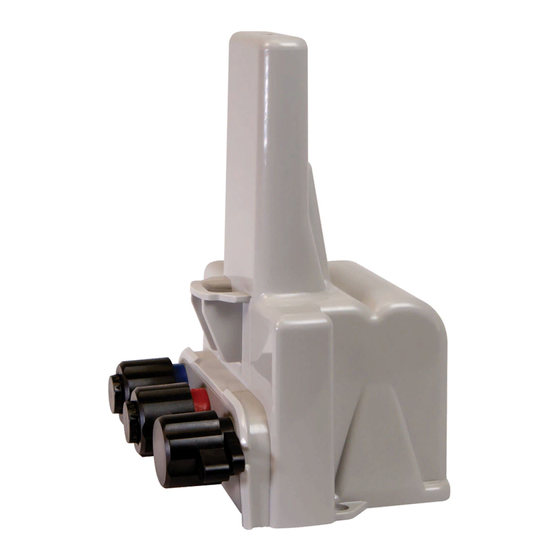
- Page 31 3. Verify that the connectors are clean and dry. 1. Black register connection 2. Red optional antenna connection 3. Blue telemetry device connection 4. Align the disconnect valve connector with the pit module's blue telemetry connector. 30 June 2021 815-0006-00 REV 007 Itron, Inc. Page 31 of 50...
- Page 32 500W ERT Module Pit Installation Guide 3 Installing the 500W ERT Pit Module 5. Push the valve connector into the pit module's connector. 6. Rotate the connector locking ring until the security holes align. 30 June 2021 815-0006-00 REV 007 Itron, Inc. Page 32 of 50...
-
Page 33: Optional Through-The-Lid Remote Antenna Installation
Twisting the connector body could damage the pit module and disconnect valve's connector pins. Install an Itron security seal through the aligned security holes. Optional Through-the-lid Remote Antenna Installation Important! The remote antenna and rod mount adapter are required for all rod and wall mount installations. -
Page 34: Innovation, Science And Economic Development Canada (Ised) Conformity
1. Thread the remote antenna connector and cable through the pit lid hole. Verify that the antenna's convex surface is on the top of the pit lid. (These instructions show a simulated pit lid material.) 30 June 2021 815-0006-00 REV 007 Itron, Inc. Page 34 of 50... - Page 35 3 Installing the 500W ERT Pit Module 2. Insert the antenna connector through the rectangular opening in the threaded collar. 3. Turn the threaded collar until it is tight against bottom of the pit lid. 30 June 2021 815-0006-00 REV 007 Itron, Inc. Page 35 of 50...
-
Page 36: Connecting
2. Push in the antenna connector to complete the connection. 3. To mount the pit module, seeInstalling the 500W ERT Pit Module on page Remote antenna installation is complete. 30 June 2021 815-0006-00 REV 007 Itron, Inc. Page 36 of 50... -
Page 37: Initializing, Connecting, And Programming The Pit Module
■ To enter an E-Coder 8-digit driver. ■ Commission security Itron strongly recommends performing a Check ERT with a handheld computer running FDM to verify that the pit module is operating correctly after installation. Performing a Check ERT will: ■... -
Page 38: Extending The Cable
Caution: Do not program configuration changes to the 500W ERT module until it is connected to the water meter register. ■ The FC300SR or Itron Mobile Radio are the only devices that support programming for the 500W ERT module. ■... - Page 39 Gnd port/black Metron Farnier OER Green Black Mueller (Hersey) Green Black Translator Sensus Green Black iPERL SRII OMNI Neptune Black Green ProRead ProRead AutoDetect E-Coder ARB-V Performance ETR Green Black 30 June 2021 815-0006-00 REV 007 Itron, Inc. Page 39 of 50...
-
Page 40: Pulser-Type Register Connections
Caution: Itron recommends pit module connections be completed using the inline connector. In rare instances, if a spliced connection is made, the Itron splice kit must be used (Itron part number OEM-0034-002). For more information, see... -
Page 41: Verifying Operation
Itron Mobile Radio connected to a user-supplied computer or Bluetooth device Caution: Verifying the 500W ERT pit module operation requires an FC300SR handheld computer or Itron Mobile Radio running FDM v4.0 or higher. Legacy Itron handheld programming devices cannot read the pit modules. -
Page 42: Using The Itron Cable Armor
U sing the Itron Cable Armor This section describes the procedure for installing Itron cable armor in a field installation. The Itron cable armor provides a layer or protection for the module's cable jacket. Itron cable armor is available in five-foot sections. - Page 43 500W ERT Module Pit Installation Guide 5 Using the Itron Cable Armor 4. Beginning over the installed electrical tape, twist the Itron cable armor onto the pit module cable using a right-handed twist. Important! You must twist—not wrap—the cable armor onto the pit module cable.
- Page 44 500W ERT Module Pit Installation Guide 5 Using the Itron Cable Armor 6. Remove any leftover materials from the customer premises. Discard or recycle leftover materials. 30 June 2021 815-0006-00 REV 007 Itron, Inc. Page 44 of 50...
- Page 45 4. Connect the register cable to the pit module connector. – Align the connectors. – Push until snug. – Twist the register cable's black coupling nut to align the two tabs. 30 June 2021 815-0006-00 REV 007 Itron, Inc. Page 45 of 50...
- Page 46 OLS or optional remote antenna Caution: Shield connectors with protective environmental caps (for more information, see Pit Module Mounting Accessories on page 19). Do not leave an exposed connector in the field. 30 June 2021 815-0006-00 REV 007 Itron, Inc. Page 46 of 50...
- Page 47 E-9R 3M® gel connector crimping tool (or other 3M approved crimping tool) ■ Itron splice kit (part number OEM-0034-002) 1. Push two wires as far as possible into the connector. Caution: Do not strip insulation from the ends of the wires before inserting them into the connector.
- Page 48 The sealant may cause minor eye and skin irritation. Avoid eye contact. Avoid prolonged or repeated skin contact. Contact Itron Support for Safety Data Sheets (SDS). 5. After the 500W ERT module to register or meter wire connections are completed, arrange the connectors in a single file.
- Page 49 500W ERT Module Pit Installation Guide 7 Completing Gel-cap Connections Using the Itron Splice Kit 6. Insert the connectors and wires into the splice tube until the connectors and wires are completely immersed in the non-conductive gel material. 7. Separate the cable wires to the sides and close the splice tube cover.
- Page 50 The handheld programmer is locked up and Soft boot the handheld. Reference the button presses produce no response. documentation for your programming device. For more information, see Related Documents on page 30 June 2021 815-0006-00 REV 007 Itron, Inc. Page 50 of 50...
Need help?
Do you have a question about the OpenWay Riva 500W ERT and is the answer not in the manual?
Questions and answers