Table of Contents
Advertisement
Quick Links
- 1 100W-R and 100Wp-R Models
- 2 Chapter 3 Initializing, Programming and Connecting the Ert Module
- 3 Initializing the 100W-R
- 4 Connecting the 100W-R to a Remote Meter Register
- 5 Connecting the 100Wp-R to a Remote Meter Register
- 6 Chapter 4 Installing the 100W-R and 100Wp-R Ert Modules
- Download this manual
Advertisement
Table of Contents

Related Manuals for ITRON 100W-R


Summary of Contents for ITRON 100W-R
- Page 1 Water Solutions 100W-R and 100WP-R Datalogging ERT Module Installation Guide TDC-0951-004...
- Page 2 Fire, explosion, and severe burn hazard. • Keep the lithium battery away from children. • Replace the lithium battery only with batteries meeting Itron specifications. Any other battery may cause a fire or explosion.
- Page 3 All product returns must be shipped by ground transportation to Itron. Suggestions If you have comments or suggestions on how we may improve this documentation, send them to TechnicalCommunicationsManager@itron.com If you have questions or comments about the software or hardware product, contact Itron Technical Support: Contact ...
-
Page 4: Table Of Contents
Attaching the Backplate ........................14 Pipe Mount Installation ........................16 Optional Leak Sensor Installation ..................... 21 Connecting the Leak Sensor to the 100W-R and 100WP-R ERT Modules ......22 Required Equipment ....................... 23 Pipe Preparation ........................23 Remote Mount Installation ......................... 27 Required Tools and Hardware .................... - Page 5 Contents Appendix A Using Gel-cap Connectors ..............37 Appendix B Troubleshooting ..................39 Index ..........................40 TDC-0951-005 100W-R and 100WP-R Datalogging ERT Module Installation Guide Proprietary and Confidential...
-
Page 6: Chapter 1 Before You Begin
Document Purpose This document provides installation instructions for the 100W-R and 100WP-R ERT modules including step- by-step instructions for pipe mount, remote mount, and direct mount. Caution Installing a remote ERT module or an integrated 100W ERT module and meter register in a water pit box will void the product warranty. -
Page 7: Related Documents
Water ERT Module Ordering Guide PUB-0063-001 Water Meter Compatibility List PUB-0063-002 mlogonline™ Network Leak Monitoring System User Guide TDC-0792-XXX Note XXX designates the document revision and is subject to change without notice. TDC-0951-005 100W-R and 100WP-R Datalogging ERT Module Installation Guide Proprietary and Confidential... -
Page 8: Chapter 2 About The 100W-R And 100Wp-R
The ERT module operates in both bubble-up mode and two-way modes. The 100W-R and 100WP-R ship in Factory Mode. The ERT modules acquire and transmit meter register data within one hour following register connection. The ERT module transfers meter data immediately if the unit is... -
Page 9: 100W-R And 100Wp-R Models
Cut Cable Flag. 100W-R encoder ERT module. The Cut Cable Flag sets if the LGR Flag is active for 24 hours. 100WP-R pulser ERT module. The Cut Cable Flag sets if the LGR Flag is active for two consecutive times. -
Page 10: 100W-R And 100Wp-R Transmission Modes
About the 100W-R and 100WP-R ERT Module 100W-R and 100WP-R Transmission Modes The 100W-R and 100WP-R ERT modules can be set to transmit in fixed network, mobile high power, mobile and handheld, or hard to read mobile and handheld mode. -
Page 11: 100Wp-R Operating Modes
The ERT module awakens from quiet mode and enters run mode in one of two ways: 1. The 100W-R detects consumption at the top of the hour (last hourly interval >1 or <-1). 2. The 100W-R receives a two-way command (for example, a Read ERT using FDM software). -
Page 12: Chapter 3 Initializing, Programming And Connecting The Ert Module
H A P T E R Initializing, Programming, and Connecting the ERT Module This chapter provides the instructions to initialize and start up the 100W-R ERT module, program and start up the 100WP-R, and connect the 100W-R or 100WP-R ERT module. -
Page 13: Programming The 100Wp-R
The 100WP-R enters run mode by completing programming with FDM. Programming sets the appropriate pulser parameters (initial consumption and Utility ID). Itron strongly recommends performing a Check ERT with a handheld computer running FDM to verify the 100WP-R is operating correctly after installation. Performing a Check ERT will: ... -
Page 14: Connecting The 100W-R To A Remote Meter Register
Initializing, Programming, and Connecting the ERT Module Connecting the 100W-R to a Remote Meter Register Connect the wires from the 100W-R ERT module to the register screw terminals according to the following table. 100W-R wire color Brown (data) Gray (power/clock) -
Page 15: Connecting The 100Wp-R To A Remote Meter Register
100WP-R transmission. Refer to the user guide for your programming device (see Related Documents on page 2) and data collection application for more information. TDC-0951-005 100W-R and 100WP-R Datalogging ERT Module Installation Guide Proprietary and Confidential... -
Page 16: Chapter 4 Installing The 100W-R And 100Wp-R Ert Modules
H A P T E R Installing the 100W-R and 100WP-R ERT Modules Install the 100W-R and 100WP-R ERT modules using one of the following mounting options: 100W-R and 100WP-R ERT modules Mounting Options Pipe Mount The ERT module mounts to a pipe near the meter (see Pipe Mount Installation). -
Page 17: Required Materials
1. Wrap the cable tie around the meter register or Leak Sensor cable. 2. Insert the pointed end of the cable tie into the receptacle end of the cable tie with the ribbed edge facing TDC-0951-005 100W-R and 100WP-R Datalogging ERT Module Installation Guide Proprietary and Confidential... - Page 18 5. Place the cable connection(s) into the ERT module housing with the cable ties to the inside. Note The image shown above illustrates the dual cable strain relief for the register and Leak Sensor. TDC-0951-005 100W-R and 100WP-R Datalogging ERT Module Installation Guide Proprietary and Confidential...
-
Page 19: Attaching The Backplate
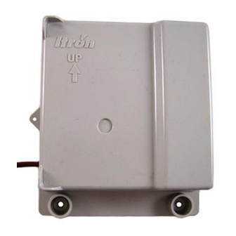
1. Route the register cable through the single backplate cutout. Ensure the cable strain relief is inside the module housing and backplate assembly. 2. Align the ERT module backplate with the mounting screw holes. Verify the Itron logo and arrow point up. TDC-0951-005 100W-R and 100WP-R Datalogging ERT Module Installation Guide... - Page 20 2. Route the register cable through the appropriate backplate cutout and the Leak Sensor cable through the remaining cutout. TDC-0951-005 100W-R and 100WP-R Datalogging ERT Module Installation Guide Proprietary and Confidential...
-
Page 21: Pipe Mount Installation
Installing the 100W-R and 100WP-R ERT Modules 3. Align the ERT module backplate with the mounting screw holes. Verify the Itron logo and arrow point up. 4. Insert a backplate mounting screw in one corner and tighten two to three turns. Insert the remaining three screws, tightening a few turns. - Page 22 Verify the pipe clamp is in the final installation position on the pipe and completely tighten the band clamp screw. 6. Place the adapter plate on the pipe bracket. The adapter-plate screw boss goes into the pipe-bracket recess. TDC-0951-005 100W-R and 100WP-R Datalogging ERT Module Installation Guide Proprietary and Confidential...
- Page 23 If the pipe is at a 45 degree angle up to the right, install the adapter plate with the mounting screws (2) as shown in the pictures below. TDC-0951-005 100W-R and 100WP-R Datalogging ERT Module Installation Guide Proprietary and Confidential...
- Page 24 If the pipe is horizontal, install the adapter plate as shown in the pictures below. To mount the 100W-R and 100WP-R ERT modules on the adapter plate 1. Locate the two 1-inch ERT module mounting screws in the Pipe Mount Kit.
- Page 25 The final installation will resemble the image below after the tamper seals are installed. Note A tamper seal is fully seated when the top of the tamper seal is approximately 1/16-inch below the top of the screw recess. TDC-0951-005 100W-R and 100WP-R Datalogging ERT Module Installation Guide Proprietary and Confidential...
-
Page 26: Optional Leak Sensor Installation
The LS is used in conjunction with both indoor (basement) and outdoor (mounting on the exterior of the house) 100W-R and 100WP-R ERT modules installations. LS devices are mounted on a water service pipe or meter insetter (meter horn) and connect to the Leak Sensor connector on the ERT module as described in Connecting the Leak Sensor to the 100W-R and 100WP-R ERT Modules on page 22. -
Page 27: Connecting The Leak Sensor To The 100W-R And 100Wp-R Ert Modules
Installing the 100W-R and 100WP-R ERT Modules Connecting the Leak Sensor to the 100W-R and 100WP-R ERT Modules Connecting a Leak Sensor to the 100W-R and 100WP-R ERT modules requires a Leak Sensor enabled ERT module. See 100W-R and 100WP-R Models on page 4. -
Page 28: Required Equipment
Caution The Leak Sensor must be mounted on the water input side of the meter. Failure to follow this mounting requirement could result in errors in the leak detection data. Installation requires Itron mounting hardware. Repair costs and service charges relating to the use on non-compliant mounting hardware will be charged to the customer. - Page 29 3. Insert the mounting U-bolt over the pipe and into the LS mounting holes. Caution Do not mount the Leak Sensor on a pipe coupler, joint, or nut. TDC-0951-005 100W-R and 100WP-R Datalogging ERT Module Installation Guide Proprietary and Confidential...
- Page 30 Caution The Leak Sensor must be mounted on the water input side of the meter. Failure to follow this mounting requirement could result in errors in the leak detection data. Installation requires Itron mounting hardware. Repair costs and service charges relating to the use on non-compliant mounting hardware will be charged to the customer.
- Page 31 4. Verify the pipe’s mounting surface is free from dirt and debris. Place the curved surface of the LS against the pipe. Caution Do not mount the Leak Sensor on a pipe coupler, joint, or nut. TDC-0951-005 100W-R and 100WP-R Datalogging ERT Module Installation Guide Proprietary and Confidential...
-
Page 32: Remote Mount Installation
Remote Mount Kit (CFG-0771-021 or CFG-1300-003) includes the back plate, tamper seals, and mounting screws Nut driver or similar tool Phillips screwdriver Drill and bits for mounting surface and screw size TDC-0951-005 100W-R and 100WP-R Datalogging ERT Module Installation Guide Proprietary and Confidential... - Page 33 4. Slide the ERT lug slot onto the mounting screw, pushing the ERT module upward until the screw head is all the way into the slot. 5. Screw the ERT module to the wall using the remaining two mounting screws. TDC-0951-005 100W-R and 100WP-R Datalogging ERT Module Installation Guide Proprietary and Confidential...
-
Page 34: Direct-Mounting To The Meter Register
When you are installing a Leak Sensor with the 100W-R or 100WP-R, you must install cable strain relief prior to installing the ERT module. For more information, see... - Page 35 Note The register may or may not be mounted on the meter when performing the following steps. 1. Direct-meter mounting requires a 100W-R ERT module for the Badger ADE register or a 100WP-R for the RTR register. Both ERTs have three wires:...
- Page 36 Installing the 100W-R and 100WP-R ERT Modules 2. Connect the ERT module wires to the register using gel-cap connectors (see Using Gel-cap Connectors page 37) following the 100W-R encoder to the Badger ADE register wire connections, (see Connecting 100W-R to a Remote Meter Register on page 8).
- Page 37 Note A gasket is not required. 6. Install four Torx-head mounting screws (SCR-0010-005) as shown below and hand-tighten the screws. Warning User Itron mounting screws (SCR-0010-005). Using the wrong mounting screws could crack the plastic ERT module housing. TDC-0951-005 100W-R and 100WP-R Datalogging ERT Module Installation Guide...
- Page 38 If the optional slotted and drilled RTR screw is used, install a wire seal through the drilled screw from (1) to (2), or as specified by utility policy. TDC-0951-005 100W-R and 100WP-R Datalogging ERT Module Installation Guide Proprietary and Confidential...
- Page 39 Note The register may or may not be mounted on the meter when performing the following steps. 1. Push the hollow pin (1) completely out of its location and separate the ERT module mounting bracket (2) from the meter register collar (3). TDC-0951-005 100W-R and 100WP-R Datalogging ERT Module Installation Guide Proprietary and Confidential...
- Page 40 Installing the 100W-R and 100WP-R ERT Modules 2. Installation requires a 100W-R ERT module for an InVISION or Scancoder register. Installation for a Digital register requires a 100WP-R. 3. Strip 1/2-inch of insulation from the end of the brown, gray, and yellow wires.
- Page 41 Installing the 100W-R and 100WP-R ERT Modules 5. Install four Torx-head mounting screws (Itron Part Number SCR-0010-005) as shown below. Hand tighten each screw. 6. Connect the ERT module wires to the register screw terminals following the 100WP-R pulser to the...
- Page 42 P P E N D I X Using Gel-cap Connectors This section describes connecting the 100W-R and 100WP-R ERT modules to the water meter register using gel cap connectors. Required Materials E-9R 3M® gel cap crimping tool Gel cap connectors 1.
- Page 43 The sealant may cause minor eye and skin irritation. Avoid eye contact. Avoid prolonged or repeated skin contact. Contact Itron Support for Material Safety Data Sheets (MSDS). TDC-0951-005 100W-R and 100WP-R Datalogging ERT Module Installation Guide...
- Page 44 P P E N D I X Troubleshooting This chapter provides the information to help you troubleshoot issues related to the 100W-R and 100WP-R ERT moduless. The following table describes possible issues and provides suggested actions to resolve the issue.
-
Page 45: Index
Using Gel-cap Connectors • i, i, i, Direct-Mounting to the Meter Register • i, Verifying 100W-R and 100WP-R ERT Module How This Document is Organized • Operation • Initializing the 100W-R • TDC-0951-005 100W-R and 100WP-R Datalogging ERT Module Installation Guide Proprietary and Confidential...
Need help?
Do you have a question about the 100W-R and is the answer not in the manual?
Questions and answers