
Related Manuals for ITRON 100G Series


Summary of Contents for ITRON 100G Series
- Page 1 100G Series Gas ERT Module, Remote Mount Installation Guide Technical knowledge to shape your future Communications...
- Page 2 Suggestions For more information about Itron or Itron products, see www.itron.com. If you have questions or comments about the software or hardware product, contact Itron Technical Support Services. Contact •...
-
Page 3: Table Of Contents
100G series gas ERT module specifications......................6 100G series gas ERT module operational specifications................7 100G Series remote module related documents....................7 Chapter 3 Mounting the 100G Series Remote Gas ERT Module.....8 Standard installation options..........................8 Mounting the remote ERT module on a pipe......................8 Adapter plate mounting configurations...................... - Page 4 Product mounting installation instructions......................66 Diaphragm meter mechanical and wiring installation instructions..............67 Remote ERT module programming and requirements notes................71 Appendix A Using gel-cap connectors to complete wiring connections..72 100G Series Gas ERT Module Installation Guide, Remote Mount TDC-0824-017 Proprietary and Confidential...
- Page 5 Appendix B Optional sealant application instructions ........73 100G Series Gas ERT Module Installation Guide, Remote Mount TDC-0824-017 Proprietary and Confidential...
-
Page 6: Chapter 1 Important Safety And Compliance Information
• Connect the equipment into an outlet on a circuit different from that to which the receiver is connected. • Consult the dealer or an experienced radio or TV technician for help. 100G Series Gas ERT Module Installation Guide, Remote Mount TDC-0824-017 Proprietary and Confidential... -
Page 7: Canada, Ised Compliance
Itron. Any unauthorized modification will void the user's authority to operate the equipment. In the event of malfunction, all repairs should be performed by Itron. It is the responsibility of users requiring service to report the need for service to Itron. -
Page 8: Lithium Battery Safety
Attempts to do so by others might void any maintenance contract with your company. Unauthorized service personnel might also be subject to shock hazard on some Itron equipment if removal of protective covers is attempted. Intrinsic safety Warning: Substitution of components may impair intrinsic safety. -
Page 9: Chapter 2 About The 100G Remote Gas Ert Module
• The 100G DLT Datalogging gas ERT module (100G DLT) is a hybrid in the Itron line of 100 Series radio frequency (RF) gas meter modules. The 100G DLT combines the circuit board hardware of the 100G DLS module with the SCM messaging used in the 100G DLN module. -
Page 10: 100G Dls Ert Module And Itron Security Manager
(such as meters installed on rooftops or in sub-basements). • Itron Cellular Solutions (ICS) Mode. The 100G DLS module is compatible with the Itron Cellular Solution and can be programmed for optimum operation with FDM Endpoint Tools Enhanced. -
Page 11: Enabling 100G Dls Ert Module Security
The installer enables the enhanced 100G DLS security at the time the ERT module is deployed or at a later time using an Itron programming device, Field Deployment Manager Endpoint Tools Enhanced, and programming commands. Initial key exchange commands are secured using the utility factory keys. -
Page 12: 100G Series Gas Ert Module Operational Specifications
NIM message FM modulation; all other messages are AM modulated 100G Series remote module related documents Documentation supporting the 100G series modules is listed in this section. Document title Document part number 100G Series Gas ERT Module Installation Guide, TDC-0823-XXX... -
Page 13: Chapter 3 Mounting The 100G Series Remote Gas Ert Module
Mount the remote ERT module using the pipe mount or wall mount (flat vertical surface) procedure. • Pipe mount. Itron offers a pipe installation kit (CFG-0005-003) to mount the remote ERT module on a pipe. • Flat vertical (wall) mount. Installation using the wall mount option places the module on a wall or other vertical surface. - Page 14 2. Turn the band clamp's screw assembly to fit into the pipe bracket opening. 3. Tighten the clamp screw until the band clamp is secure on the pipe. 100G Series Gas ERT Module Installation Guide, Remote Mount TDC-0824-017 Proprietary and Confidential...
- Page 15 Tighten the module mounting screws evenly in an alternating pattern. Tighten the screws to 9 to 12 inch- pounds torque. 10. Insert the tamper seals. 100G Series Gas ERT Module Installation Guide, Remote Mount TDC-0824-017 Proprietary and Confidential...
-
Page 16: Adapter Plate Mounting Configurations
1. Drill three pilot holes in the mounting surface. The drilled pilot holes for the two bottom screws must be on a horizontal line. 1. 3 inches 2. 1-11/16 inches 3. 3-3/8 inches 100G Series Gas ERT Module Installation Guide, Remote Mount TDC-0824-017 Proprietary and Confidential... - Page 17 4. Place a new tamper seal over each bottom ERT module mounting screw as required. Note: To reduce the risk of cable damage, secure any excess ERT module cabling with a cable tie. 100G Series Gas ERT Module Installation Guide, Remote Mount TDC-0824-017 Proprietary and Confidential...
-
Page 18: Chapter 4 100G Series Remote Module Programming
Deployment Manager (FDM) software version 1.1 or higher and a compatible programming device. The 100G DLS ERT modules support enhanced security with the Itron Security Manager. Enabling command or enhanced security requires additional programming. Program the 100G DLS ERT modules using an approved programming device loaded with Field Deployment Manager (FDM) software version 3.3 or higher. -
Page 19: Itron Programs And Software Variables
This section defines and clarifies possible system variables you may encounter in programming 500G ERT modules. Field Deployment Manager (FDM) The following tables illustrate various FDM programming configurations and the endpoint response to each setting. 100G Series Gas ERT Module Installation Guide, Remote Mount TDC-0824-017 Proprietary and Confidential... - Page 20 100G Series Remote Module Programming 100G Series Gas ERT Module Installation Guide, Remote Mount TDC-0824-017 Proprietary and Confidential...
- Page 21 The request to input the dial and drive rate information happens only if the system has more than one option using the same count rate and rollover variable enabled in their FDM business unit. 100G Series Gas ERT Module Installation Guide, Remote Mount TDC-0824-017 Proprietary and Confidential...
- Page 22 100G Series Remote Module Programming Note: Itron recommends that users only enable the configurations used by your business unit. Having only one meter configuration option enabled (with the endpoint variable being checked in the FDM business unit) eliminates the need to enter the number of dials.
-
Page 23: Chapter 5 Specific Meter Manufacturer Installation
This chapter provides information for installing the 100G remote ERT module to compatible meters. Reference each section for compatible meters. Eagle Research meter installation This section provides the information to install the 100G series remote ERT module on the following compatible Eagle Research correctors. Meter model... -
Page 24: Eagle Research Product Mounting Instructions
For more information, see Optional sealant application instructions page 73. 4. Programming the 100G series remote ERT module. Programming requires an Itron ERT programming device (for example, an FC300SR). For programming information, see 100G Series Remote Module Programming on page 13 100G series module configuration with the meter is dependent on your system application. -
Page 25: Eagle Research Mechanical And Wiring Installation Instructions
6. Connect the twisted blue and white wires to terminal 15 on the MPplus terminal block. 7. Connect the red remote ERT module wire to terminal 16 on the MPplus terminal block. 100G Series Gas ERT Module Installation Guide, Remote Mount TDC-0824-017 Proprietary and Confidential... -
Page 26: Connecting The 100G Ert Module To The Xartu Corrector
For XARTU-1 corrected reads: 8. With the XARTU door open, insert the flying leads from the remote ERT module into the compression connector on the left of the corrector's housing. 100G Series Gas ERT Module Installation Guide, Remote Mount TDC-0824-017 Proprietary and Confidential... -
Page 27: Eagle Research Corrector Programming And Requirements Notes
Research product documentation to verify the most current programming and configuration information for the 100G series remote ERT module. Using Itron 100G series remote ERT modules with Eagle Research volume correctors requires Eagle Research Field Manager software configured with the parameters for your model of Eagle Research corrector. -
Page 28: Using Eagle Research Field Manager To Change The Mpplus Settings
• Connection Type: Direct • Communications Port: enter your computer's port number • Baud Rate: enter the baud rate that displayed in Step. 2. 5. Click OK. 6. Click View/Config. 100G Series Gas ERT Module Installation Guide, Remote Mount TDC-0824-017 Proprietary and Confidential... - Page 29 9. Enter the parameters shown in the Corrected Pulse Output Setup section in the lower left of the window. 10. Click Send All Changes. 11. Verify that all parameters are correct. 12. Click Disconnect. 100G Series Gas ERT Module Installation Guide, Remote Mount TDC-0824-017 Proprietary and Confidential...
-
Page 30: Using Eagle Research Field Manager To Change The Xartu Corrector Settings
7. Enable K2 (4, 5, 6) and set additional parameters are required in the Uncorrected Pulse Output Setup section in the lower right of the window. 100G Series Gas ERT Module Installation Guide, Remote Mount TDC-0824-017 Proprietary and Confidential... -
Page 31: Eagle Research Programming Note
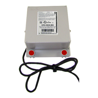
Elster American RPM 100G DLT Datalogging ERG-5007-503 Series rotary meter Elster American installation overview Installing the 100G series remote ERT module to an Elster American meter involves four tasks. 100G Series Gas ERT Module Installation Guide, Remote Mount TDC-0824-017 Proprietary and Confidential... -
Page 32: Elster American Meter Mounting Instructions
100G Series Remote Module Programming on page 13. Programming requires an Itron ERT programming device (for example, an FC300SR). 100G series module configuration with the meter is dependent on your system application. See the Elster American meter configuration information. Elster American meter mounting instructions 1. -
Page 33: Elster American Mechanical And Wiring Installation Instructions
5 mm screws. Elster American mechanical and wiring installation instructions Note: Connection to an Elster American meter requires a cable interface compatible to an Elster American RPM rotary meter. 100G Series Gas ERT Module Installation Guide, Remote Mount TDC-0824-017 Proprietary and Confidential... - Page 34 5. Insert the meter cable through the slot on the ERT module backplate. Install a cable tie to the meter cable wire below the meter cable insulation to provide strain relief. 100G Series Gas ERT Module Installation Guide, Remote Mount TDC-0824-017 Proprietary and Confidential...
-
Page 35: Installing The Remote Module Cable
GasMicro Electronic Volume Corrector Galvanic installation overview Installing the 100G series remote ERT module to a Galvanic volume corrector involves four tasks. 100G Series Gas ERT Module Installation Guide, Remote Mount TDC-0824-017 Proprietary and Confidential... -
Page 36: Galvanic Product Mounting Instructions
13. Programming requires an Itron ERT programming device (for example, an FC300SR). 100G series module configuration with the meter is dependent on your system application. See the Galvanic corrector product documentation for configuration information. Galvanic product mounting instructions Note: See the Galvanic product documentation for custom mounting instructions. - Page 37 100G Datalogging FN ERG-5003-503 100G Datalogging FN ERG-5003-505 100G DLS Datalogging ERG-5006-503 Electronic 100G DLS Datalogging ERG-5006-505 Temperature 100G DLT Datalogging ERG-5007-503 Compensator (ETC) 100G DLT Datalogging ERG-5007-505 100G Series Gas ERT Module Installation Guide, Remote Mount TDC-0824-017 Proprietary and Confidential...
-
Page 38: Ge Dresser Meter Installation Overview
Specific Meter Manufacturer Installation GE Dresser meter installation overview Installing the 100G series remote ERT module to a GE Dresser meter involves the following tasks. 1. Programming or verifying that the meter is set up to work with the 100G remote ERT module. -
Page 39: Ge Oil And Gas Es3 Or Etc Ordered With The Amr-Ready Mounting Kit
Caution: Upright vertical positioning is critical because: • The 100G series modules are optimized for communication and require upright mounting. Any other mounting position could result in reduced RF performance. • The remote module tilt tamper sensor requires upright mounting. Any other mounting position may cause issues with the module's tilt tamper detection. - Page 40 Any other installation orientation will compromise battery life. 5. Secure the ERT module/bracket assembly on the IMC\W2 using four ERT module/mounting bracket screws (M6 x 20 mm). Install tamper seals as required. 100G Series Gas ERT Module Installation Guide, Remote Mount TDC-0824-017 Proprietary and Confidential...
-
Page 41: Ge Oil And Gas Mechanical And Wiring Installation Instructions
D800/D1000 wiring and installation 1. Loosen and remove the two screws holding the mounting brackets to the meter. 2. After the brackets are removed, the pulse output cable is visible. 100G Series Gas ERT Module Installation Guide, Remote Mount TDC-0824-017 Proprietary and Confidential... - Page 42 Brown White and blue White Output 1- Green Output 2+ White White and blue White Output 2- Black Output 3+ White White Output 3- Blue Blue Blue 100G Series Gas ERT Module Installation Guide, Remote Mount TDC-0824-017 Proprietary and Confidential...
- Page 43 14. Tilt the bottom of the ERT module away from the mounting bracket and slide the notched mounting hub onto the screw and Kep nut. Do not tighten the screw. 100G Series Gas ERT Module Installation Guide, Remote Mount TDC-0824-017 Proprietary and Confidential...
-
Page 44: Ge Oil And Gas Meters With Pulse Output Wiring
See the specific wiring configuration for your product. Wiring configurations for the B3, LMMA, IMC/W2, MC2, ES3, and ETC meters with pulse outputs are provided in the following information. 100G Series Gas ERT Module Installation Guide, Remote Mount TDC-0824-017 Proprietary and Confidential... - Page 45 4. Tuck the three gel connectors and cable tie inside the module housing, as shown in the placement illustration and schematic. 100G Series Gas ERT Module Installation Guide, Remote Mount TDC-0824-017 Proprietary and Confidential...
-
Page 46: Ge Oil And Gas Meter Programming And Requirements Notes
Specific Meter Manufacturer Installation Wiring for direct connection to the IMC/W2 5. Install the 100G series remote gas module backplate using the four screws previously removed from the module and a Torx T-10 screwdriver. 6. Plug the cable into the pulse output of the index. -
Page 47: Honeywell Instrument Installation
2. Using the GE Dresser User Terminal (UT) communications software, connect to the IMC/W2. Read the uncorrected or corrected count number on the remote ERT module with the Itron endpoint reading device. Compare the IMC/W2 uncorrected or corrected amounts to those from the remote ERT module. -
Page 48: Honeywell Instrument Installation Overview
ERG-5007-503 tamper. Honeywell Instrument installation overview Installing the 100G series remote ERT module to a Honeywell Instrument involves four tasks. 1. Programming the instrument and verifying that the Honeywell instrument is set up to work with the 100G remote ERT module. Programming requires Honeywell software. -
Page 49: Honeywell Product Mounting Instructions
#8-32 x 3/8-inch screws. Align the lower threaded holes in the mounting bracket with the drilled enclosure holes and insert a screw/washer through the enclosure housing. Screws heads must be inside the enclosure. Tighten both screws using a screwdriver. 100G Series Gas ERT Module Installation Guide, Remote Mount TDC-0824-017 Proprietary and Confidential... -
Page 50: Honeywell Mechanical And Wiring Installation Instructions
Connecting the remote ERT modules to a Honeywell Mini-AT, Mini-Max, or EC-AT With Itron 100G remote ERT modules, utilities can receive corrected and uncorrected consumption values by installing two ERT modules. The ERT module for corrected reads is attached to the corrector's pulse output. The ERT module for uncorrected reads is attached to the input switch board. - Page 51 Ya terminal Blue* Ya terminal White* *Twist the blue and white ERT module wires together before connecting them to the Mini-Max board. Tighten the terminal connection securely. 100G Series Gas ERT Module Installation Guide, Remote Mount TDC-0824-017 Proprietary and Confidential...
-
Page 52: Connecting The Remote Ert Module To The Honeywell Tci
Connections to the three output pulse channels are completed using loose unterminated wires (the individual wires from a cable) and gel-connectors. The TCI unit has six unterminated wires that require six gel-connectors (Itron part number CON-0023-001) to enable pulse connections to ancillary devices. Loose wires are located inside the gray adapter plate behind the black strain relief fitting. - Page 53 TCI). 8. Insert the appropriate field cable wire into the other gel-connector opening. 9. Verify both wires are fully inserted into the gel-connector prior to crimping. 100G Series Gas ERT Module Installation Guide, Remote Mount TDC-0824-017 Proprietary and Confidential...
-
Page 54: Honeywell Instrument Programming And Requirements
Important: This information is subject to change without notice. Refer to the Honeywell MasterLink SQL product documentation to verify the most current information about programming and configuring the corrector for use with the 100G series remote ERT module. Honeywell software settings 1. -
Page 55: Programming The Honeywell Instrument Parameters
FormC1 board channel (for FormA 4=0.5sec example, Ka/Ya; kb/Yb; Kc/Yc) Mini with Main Form A board Ka, Ya=Channel A main Type-2* board Kb, Yb=Channel B 100G Series Gas ERT Module Installation Guide, Remote Mount TDC-0824-017 Proprietary and Confidential... -
Page 56: Itron Meter Installation
100G 100G board Itron meter installation This section describes 100G series remote gas ERT module installation on Itron meter. Installation information for the A-Series (1A, 305, 400, 675, and 1000) meters, see Diaphragm Meter Installation on page 65. Meter model... -
Page 57: Itron Meter Installation Overview
• Tools and devices to complete installation and programming. Installing the remote module to a DATTUS III meter involves five tasks: 1. Programming the meter (see the Itron DATTUS-Link Programming Guide for more information). 2. Installing any necessary Itron retrofit parts. Customers can request that Binder connectors be installed by Itron prior to shipment. -
Page 58: Itron Product Mounting Instructions
Connecting the module following the information in this section requires a pulse output cable, installed by Itron. Pulse output cables are available in 10-foot and 20- foot lengths. Factory-installed cables have a Binder connector on one end and three bare wires on the opposite end. -
Page 59: Itron Meter Programming And Requirements
100G DLS Datalogging ERG-5006-501 100G DLT Datalogging ERG-5007-501 Romet meter installation This section describes installation for Romet meters and correctors compatible with Itron 100G series remote ERT modules. Meter model Meter notes 100G remote module type Itron part ERT module notes... -
Page 60: Romet Installation Overview
• Pipe mount using the Itron pipe mount kit CFG-0005-003 • Custom Romet mounting (see Romet documentation for custom mounting) 4. Programming the 100G series remote ERT module. For programming information, see 100G Series Remote Module Programming on page 13. Programming requires an Itron ERT programming device (for example, an FC300SR). -
Page 61: Romet Product Mounting Instructions
These instructions describe installation with Romet cables and setup options for the AdEM corrector and ECM2® meter. These instructions include the two most common setup configurations. For specialized setup instructions, contact Romet. 100G Series Gas ERT Module Installation Guide, Remote Mount TDC-0824-017 Proprietary and Confidential... - Page 62 (temporarily) in a safe, secure place. 2. Insert the lead wires from the module into new 3M gel connectors (Itron part number CON-0023-001) together with the lead wire from the meter cable (see wiring connections).
- Page 63 White and blue White and blue Romet cable number 34-125-43 Cable pin ERT module wire Corrected Aux CC Alarm White and blue White and blue White and blue 100G Series Gas ERT Module Installation Guide, Remote Mount TDC-0824-017 Proprietary and Confidential...
- Page 64 White and blue White and blue White and blue Romet cable number 34-125-51 Cable pin ERT module wire Correct Uncorrected Aux CC White and blue White and blue 100G Series Gas ERT Module Installation Guide, Remote Mount TDC-0824-017 Proprietary and Confidential...
-
Page 65: Romet Corrector Programming And Requirements Notes
Torque the backplate mounting screws to 9 to 12 inch- pounds. 8. Install the module on the wall or a pipe using the pipe installation kit (Itron part number CFG-0005-003) or install the module on the Romet AdEM meter using the Romet ERT mounting bracket (Romet part number 46-444-2). - Page 66 ® ECM2 programming 4. Set the ECM2 output pulse spacing to 750ms for operation with the 100G remote ERT module. Output spacing represents an off-time between pulses. 100G Series Gas ERT Module Installation Guide, Remote Mount TDC-0824-017 Proprietary and Confidential...
-
Page 67: Sensus Meter Installation
Specific Meter Manufacturer Installation Sensus meter installation This section describes 100G series remote ERT module on compatible Sensus meters. Meter model Meter notes 100G remote module type Itron part ERT module notes number Sonix meters are pulse 100G ERG-5000-503 output registers which... -
Page 68: Sensus Meter Mechanical And Wiring Installation Instructions
You may connect the Sensus Sonix meter to the remote module using the pulse output cable or you can directly mount the remote ERT module to the meter. 100G Series Gas ERT Module Installation Guide, Remote Mount TDC-0824-017 Proprietary and Confidential... -
Page 69: Sensus Meter Programming And Requirements Notes
Using the SonixCom software, configure the Sensus Sonix meter parameters with the following the Sensus pulse output settings. • 1 pulse per 10 cf • 1 pulse per 100 cf • 1 pulse per 1000 cf 100G Series Gas ERT Module Installation Guide, Remote Mount TDC-0824-017 Proprietary and Confidential... -
Page 70: Chapter 6 Diaphragm Meter Installation
Chapter 6 Diaphragm Meter Installation This chapter provides the instructions to install remote modules (Itron part number ERG-500X-501 with 2.5-foot cable and encoder) on diaphragm gas meters where a direct mount ERT module is not possible. Meter model Meter notes... -
Page 71: Product Mounting Installation Instructions
The Itron replacement index cover gaskets shown below are thicker than standard gaskets and have a special slot to accommodate the encoder cable. Gaskets are designed for Schlumberger/Sprague model 675 and 1000 commercial diaphragm meters. These gaskets may be incompatible on meters from other manufacturers;... -
Page 72: Diaphragm Meter Mechanical And Wiring Installation Instructions
2. Remove the old gasket and any gasket residue from the meter and index cover. 3. Remove the magnet hub from the encoder installation kit (Itron part number CFG-0081-001). Verify there is only one magnet in the hub. Note: If there is no magnet or if there are two magnets in the magnet hub, discard the hub. Encoder installation requires a magnet hub with one magnet. - Page 73 10. Remove the acetone stick applicator from the remote encoder installation kit (Itron part number CFG-0081-001). Select a location on the index face next to the magnet hub for the encoder installation.
- Page 74 13. Peel the protective plastic away from the adhesive side of the encoder. Important: You must do the next two steps exactly as described or the 100G series remote gas module will not work properly. 14. Press the curved side of the encoder firmly against the side of the encoder spacing tool as shown below, with the adhesive side down.
- Page 75 22. Verify that the encoder cable is in the correct position in the cable slot of the gasket. Fully tighten the screws in an alternating pattern. Install utility-approved security seals and wires as required. This completes the diaphragm meter installation. 100G Series Gas ERT Module Installation Guide, Remote Mount TDC-0824-017 Proprietary and Confidential...
-
Page 76: Remote Ert Module Programming And Requirements Notes
Take note of the index drive rate shown on the index. The ERT is programmed based on the drive rate. Elster American commercial meter index drive rates may be 5-, 10- or 100 cubic feet. The index shown has a 10-cubic foot drive rate. 100G Series Gas ERT Module Installation Guide, Remote Mount TDC-0824-017 Proprietary and Confidential... -
Page 77: Appendix A Using Gel-Cap Connectors To Complete Wiring Connections
The sealant may cause minor eye and skin irritation. Avoid eye contact. For more information or Safety Data Sheet (SDS) information, visit the manufacturer website. 100G Series Gas ERT Module Installation Guide, Remote Mount TDC-0824-017 Proprietary and Confidential... - Page 78 Appendix B Optional sealant application instructions In areas where insect intrusion is a problem, Itron recommends an optional sealant to help keep insects out of the ERT module housing. The Itron-tested and approved sealant (Itron part number ADH-5106-000) is used to seal gaps in remote ERT module installations that can allow insect intrusion.
Need help?
Do you have a question about the 100G Series and is the answer not in the manual?
Questions and answers