ITRON OpenWay Riva User Manual
Act module
Hide thumbs
Also See for OpenWay Riva:
- Installation manual (43 pages) ,
- Installation manual (42 pages) ,
- Installation manual (34 pages)
Advertisement
Quick Links
Download this manual
See also:
Installation Manual
Itron OpenWay® Riva™ ACT Module
Note: To maintain the compliance with radiation protection, place the product at least 20 cm from nearby
persons.
The operation of the OpenWay® Riva™ ACT Module assumes you start with a CGR1240 as shipped from
Cisco. The CGR1240 will look like the picture below assuming there is a cellular backhaul module installed
in Slot 3:
Revision 1.0
USER MANUAL
Page 1
Advertisement

Related Manuals for ITRON OpenWay Riva


Summary of Contents for ITRON OpenWay Riva
- Page 1 Itron OpenWay® Riva™ ACT Module USER MANUAL Note: To maintain the compliance with radiation protection, place the product at least 20 cm from nearby persons. The operation of the OpenWay® Riva™ ACT Module assumes you start with a CGR1240 as shipped from Cisco.
- Page 2 1.0 Installing the OpenWay® Riva™ ACT Module The OpenWay® Riva™ ACT Module will then be inserted into Slot 6 as shown in the picture below: Revision 1.0 Page 2...
- Page 3 1.1 Connect the QMA cable to the connector on the OpenWay® Riva™ ACT Module that is closest to the center of the CGR. Revision 1.0 Page 3...
- Page 4 2.0 Configuring the CGR Now plug in the CGR1240 and wait for about 20 minutes while the CGR boots up and configures itself. 2.1 Connect the USB cable to a PC using the RJ45 Ethernet to DB9cable provided using a DB9 to USB adaptor as shown below: Revision 1.0 Page 4...
- Page 5 2.2 Open Tera Term or a comparable software terminal emulator program. Set the baud rate on the PC to 9600 baud as shown below: Revision 1.0 Page 5...
- Page 6 2.3 Type the following commands into Tera Term: show_module enable #hw-module_poweroff_6 (powers off Slot 6) #no_hw-module_poweroff_6 (powers on Slot 6) Revision 1.0 Page 6...
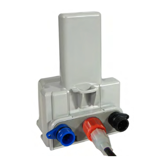
- Page 7 2.4 CGR with OpenWay® Riva™ ACT Module is now ready to accept instructions for the application code to run. 3.0 Configuring the ACT PLC Coupler Revision 1.0 Page 7...
- Page 8 ACT PLC Coupler should be attached to the adaptor plate as shown below: 3.1 Connect one end of the AC Input Cable 010415-06 as shown below: Revision 1.0 Page 8...
- Page 9 3.2 Connect one end of the AC Output cable 010415-08 as shown below: Revision 1.0 Page 9...
- Page 10 3.3 Connect one end of the PLC Cable 010415-07 as shown below: Revision 1.0 Page 10...
- Page 11 3.4 Connect the other end of the AC Output cable 010415-08 to the CGR1240 AC Input bulkhead connector as shown below: Revision 1.0 Page 11...
- Page 12 3.5 Connect the other end of the PLC Cable 010415-07 to the CGR1240 PLC Coupler bulkhead connector as shown below: Revision 1.0 Page 12...
- Page 13 3.6 The RIVA ACT System is now ready to function properly. Revision 1.0 Page 13...
Need help?
Do you have a question about the OpenWay Riva and is the answer not in the manual?
Questions and answers