Table of Contents
Advertisement
Quick Links
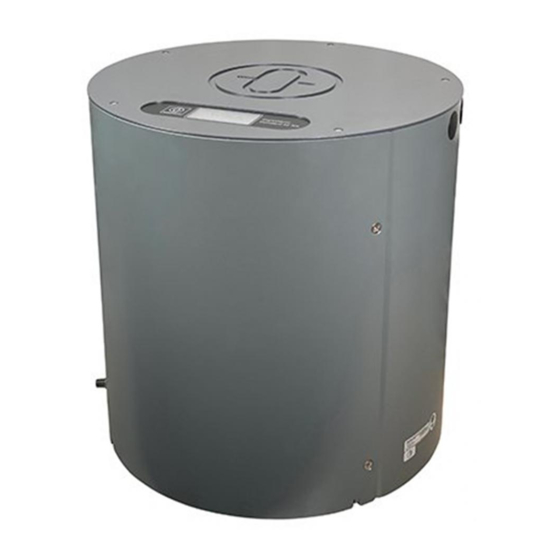
STD 22 Compact GYRO COMPASS
and
STD 22 GYRO COMPASS
Type 110- -233
Installation and Service manual
3646/110--233.DOC010302
Edition:
May 20, 2005
Revision:
July 1, 2005
Revision:
Sept. 13, 2005
Revision:
Nov. 28, 2005
Revision:
Feb. 17, 2006
Raytheon Anschütz GmbH
Postfach 1166
D - - 24100 Kiel
Germany
Tel +49- -4 31- -30 19- -0
Fax +49- -4 31- -30 19- -501
Email Service@raykiel.com
www.raytheon- -anschuetz.de
Advertisement
Table of Contents

Subscribe to Our Youtube Channel
Related Manuals for Raytheon Anschütz STD 22 Compact GYRO COMPASS


Summary of Contents for Raytheon Anschütz STD 22 Compact GYRO COMPASS
- Page 1 D - - 24100 Kiel Germany Tel +49- -4 31- -30 19- -0 Fax +49- -4 31- -30 19- -501 Email Service@raykiel.com www.raytheon- -anschuetz.de STD 22 Compact GYRO COMPASS STD 22 GYRO COMPASS Type 110- -233 Installation and Service manual 3646/110--233.DOC010302 Edition:...
- Page 2 Weitergabe sowie Vervielfältigung dieser Unterlage, Verwertung und Copying of this document, and giving it to others and the use or Mitteilung ihres Inhaltes nicht gestattet, soweit nicht ausdrücklich communication of the contents thereof, are forbidden without express zugestanden. Zuwiderhandlungen verpflichten zu Schadenersatz. authority.
- Page 3 CAN bus (CAN = Controller Area Network) ....Preparing to install the STD 22 Compact Gyro Compass ..STD 22 Compact Compass – Scope of Supply .
- Page 4 Installation and Service manual Compass STD 22 Compass STD 22 Compact Preparing to install the STD 22 Gyro Compass ... . . STD 22 Compass – Scope of Supply ......3.1.1 General information concerning installation of the STD 22 Compass...
- Page 5 Installation and Service manual Compass Compass STD 22 STD 22 Compass STD 22 Compact Error messages and warnings ......Error messages .
- Page 6 Installation and Service manual Compass STD 22 Compass STD 22 Compact intentionally left blank Edition: May 20, 2005 3646/110--233.DOC010302...
- Page 7 Installation and Service manual Compass Compass STD 22 STD 22 Compass STD 22 Compact 3646/110--233.DOC010302 Edition: May 20, 2005...
- Page 8 Installation and Service manual Compass STD 22 Compass STD 22 Compact Edition: May 20, 2005 3646/110--233.DOC010302...
- Page 9 Installation and Service manual Compass Compass STD 22 STD 22 Compass STD 22 Compact 3646/110--233.DOC010302 Edition: Feb. 17, 2006...
- Page 10 Installation and Service manual Compass STD 22 Compass STD 22 Compact VIII Edition: Feb. 17, 2006 3646/110--233.DOC010302...
- Page 11 Installation and Service manual Compass STD 22 Compass Compass STD 22 Compact STD 22 Safety notes Caution: Maintenance and repair work should be carried out only by trained and qualified staff who are well versed in national safety regulations. After the gyro compass has been switched off it is necessary to wait at least 15 minutes before accessing the interior of the gyro compass.
- Page 12 Installation and Service manual Compass STD 22 Compass STD 22 Compact Caused by technical progress the PC--Boards of the Gyro Compass are changed. Due to that some pictures and/or procedures have been changed. Respective changes are marked with “E10”. The AC supply voltage (ships mains) may drop out. This leads to a restart of the gyrocompass and a new settling stage.
- Page 13 CAN bus system with an Operator Unit and a Distribution Unit. In the case of the STD 22 Compact Gyro Compass, the CAN bus is not enabled. The following diagrams provide an overview of the possible applications of the STD 22 Compact and STD 22 Gyro Compasses.
- Page 14 Installation and Service manual Compass STD 22 Compass STD 22 Compact Edition: Feb. 17, 2006 3646/110--233.DOC010302...
- Page 15 Installation and Service manual Compass STD 22 Compass Compass STD 22 Compact STD 22 Edition: Feb. 17, 2006 3646/110--233.DOC010302...
- Page 16 Installation and Service manual Compass STD 22 Compass STD 22 Compact CAN bus Edition: Feb. 17, 2006 3646/110--233.DOC010302...
- Page 17 Installation and Service manual Compass STD 22 Compass Compass STD 22 Compact STD 22 CAN bus Edition: May 20, 2005 3646/110--233.DOC010302...
- Page 18 Installation and Service manual Compass STD 22 Compass STD 22 Compact CAN bus Edition: Feb. 17, 2006 3646/110--233.DOC010302...
- Page 19 Installation and Service manual Compass STD 22 Compass Compass STD 22 Compact STD 22 Edition: Feb. 17, 2006 3646/110--233.DOC010302...
- Page 20 Installation and Service manual Compass STD 22 Compass STD 22 Compact CAN bus Edition: Feb. 17, 2006 3646/110--233.DOC010302...
- Page 21 Installation and Service manual Compass STD 22 Compass Compass STD 22 Compact STD 22 CAN bus Edition: Feb. 17, 2006 3646/110--233.DOC010302...
- Page 22 Installation and Service manual Compass STD 22 Compass STD 22 Compact CAN bus Edition: Feb. 17, 2006 3646/110--233.DOC010302...
- Page 23 Installation and Service manual Compass STD 22 Compass Compass STD 22 Compact STD 22 CAN bus (CAN = Controller Area Network) (CAN = Controller Area Network) The CAN bus is a Multi-Master-Bus allowing the connection of all devices and systems regardless CAN bus of their task and function.
- Page 24 Installation and Service manual Compass STD 22 Compass STD 22 Compact intentionally left blank Edition: May 20, 2005 3646/110--233.DOC010302...
- Page 25 STD 22 Preparing to install the STD 22 Compact Gyro Compass To ensure that the STD 22 Compact Gyro Compass is installed and put into operation correctly, these instructions must be followed in the order in which they appear. It must not be installed or put into operation whilst at sea.
- Page 26 Installation and Service manual Compass STD 22 Compact General information concerning installation of the STD 22 Compact Compass When fitting components, observe the following spacing: Fit the compass enclosure so that the display can be viewed from above and the cover of the enclosure can be removed (see also Dimensional Drawing 110--233.HP005).
- Page 27 2.3.1 General information concerning on-board wiring The cables which are to be connected to the STD 22 Compact Gyro Compass are led through one of the cable entries at the top of the compass enclosure and fixed in the cable entry with a cable clip suitable for the size of the cable.
- Page 28 Installation and Service manual Compass STD 22 Compact -- Push the components of the screw fastening over the cable. It is essential to follow the sequence (as shown in Figure 3). -- Check the cone and the mating piece of the earthing insert for corrosion and if necessary remove corrosion with an emery cloth.
- Page 29 Installation and Service manual Compass Compass STD 22 Compact STD 22 Supply voltage Coursebus CAN bus Function “Quick Settling” Note: The connection cables should be shortened in that way, that they could be led to the terminal boards without mechanical stress. Too long connection cables will lead to EMC problems.
- Page 30 Installation and Service manual Compass STD 22 Compact 2.3.1.1 General information about creating an earth connection The following instructions relating to the creation of cable connections must be adhered to in order to comply with the stringent EMC requirements. The specified cable types must be used. It is vital to ensure that these connections have a common reference to ship’s earth.
- Page 31 Installation and Service manual Compass Compass STD 22 Compact STD 22 Installing the compass and putting it into operation 2.4.1 Remove the transportation support with outer sphere, supporting liquid and distilled water. -- Undo the 4 screws (Figure 6 /1) at the top and bottom of the enclosure door, lift out the door and detach the earthing strip (Figure 6/2) on the inside of the door.
- Page 32 Installation and Service manual Compass STD 22 Compact 2.4.1.1 Assembling the compass enclosure Note: It is not necessary to install the compass enclosure with reference to the ship (e.g. in the ship’s forward direction). It can be installed in whatever position is most convenient for servicing and operation.
- Page 33 Installation and Service manual Compass Compass STD 22 Compact STD 22 The compass enclosure must be installed in such a way that the following requirements are met: -- The 8 supports must all stand on a flat, firm surface. If necessary, the user should himself create an intermediate plate (marine quality hardwood or metal) suited to the local conditions.
- Page 34 Installation and Service manual Compass STD 22 Compact STD 22 Compact The compass must be mounted so that it is perpendicular to the horizon (+/-- 2 mm). This arrangement prevents compass functions from being impaired by the rolling and pitching of the vessel. max.1°...
- Page 35 Installation and Service manual Compass Compass STD 22 Compact STD 22 2.4.1.2 Installation of the gyrosphere Special tool required: Suction cup Installation procedure: -- Undo the six screws (Figure 9/1) fastening the upper and lower halves of the outer sphere (Figure 9/2 and 3). -- Remove plug B3 (Figure 9/4) from the plug plate.
- Page 36 Installation and Service manual Compass STD 22 Compact Insert the gyrosphere into the lower outer sphere Remove he upper half of the outer sphere Figure 10: Principle of separating the upper and lower halves of the outer sphere – inserting the gyrosphere -- Replace the upper half of the outer sphere on the lower half.
- Page 37 Installation and Service manual Compass Compass STD 22 Compact STD 22 2.4.1.3 Filling with distilled water and supporting liquid. (see Figure 11) -- Undo the three plastic screws (Figure 11/1--3) on the upper outer sphere distilled water supporting liquid filling tool vent Figure 11: Filling with liquids -- Fit the supplied filling device on the distilled water bottle.
- Page 38 Installation and Service manual Compass STD 22 Compact -- Pour approximately 840 cm of supporting liquid in the appropriate filling opening (look for the identifying label). The supporting liquid must be at room temperature (over 25° C) and the measuring cone should fill half the measuring range (diameter).
- Page 39 Installation and Service manual Compass Compass STD 22 Compact STD 22 2.4.1.4 Inserting the outer sphere in the compass enclosure (see Figure 13) -- Carefully insert the gyrosphere in the compass enclosure: Pay attention to the two locking pins on the closure. -- Using both hands, hold the outer sphere and guide it under the snap closures (Figure 13/1) on the pendulum joint (Figure 13/2).
- Page 40 Installation and Service manual Compass STD 22 Compact -- Using the thumbs, press down and engage two snap closures (Figure 13/1). -- Turn the outer sphere through 90° and repeat the process with the two other snap closures. The outer sphere is now fastened to the pendulum joint -- Guide the cable around the outer sphere and attach the plugs to the small PCB of the outer sphere, tighten the fastening screws Edition: May 20, 2005...
- Page 41 Installation and Service manual Compass Compass STD 22 Compact STD 22 Creating cable connections and plug connections 2.5.1 Overview of plug connections and fuses on PCB‘s (see also section 4 for more information about LED‘s, plugs, push buttons and jumper) Sensor PCB Power Supply PCB Connection PCB...
- Page 42 Installation and Service manual Compass STD 22 Compact Figure 15: Arrangement of plugs, terminal boards and fuses Terminal L1 Power supply (24VDC) Fuse E1 (T10A) Power supply (24VDC) Plug B2 Output Channel1 Course Bus/NMEA Fuse E2 (T1A) Channel1 +24V Plug B3 Output Channel2 Course Bus/NMEA Fuse E3 (T1A) Channel2 +24V...
- Page 43 Compass STD 22 Compact STD 22 2.5.1.1 Connecting the course receiver in the STD 22 Compact Gyro Compass (see also Cable and Connection Diagram 110--233.HP010) Three outputs are provided on the Connection PCB of the gyro compass for course data:...
- Page 44 Installation and Service manual Compass STD 22 Compact Course receivers should be connected with a screened cable having up to 6 poles (appr. 0.5mm per conductor). Output 1 Plug B2 Connection 3 (Channel 1) Connection 4 Tx-- Connection 5 Tx GND Connection 1 24VDC Connection 2...
- Page 45 Installation and Service manual Compass Compass STD 22 Compact STD 22 2.5.1.2 Connecting status and control signal outputs in the STD 22 Compact Gyro Compass The following status signals and signals for external signalling can tapped from the Connection PCB of the Gyro compass. AVAILABLE compass data available SYSTEM...
- Page 46 Installation and Service manual Compass STD 22 Compact AVAILABLE Plug B6 Connection 7 Connection 8 SYSTEM Plug B6 Connection 5 Connection 6 Plug B6 Connection 1 Connection 2 Plug B6 Connection 3 see also section 2.6.3.1 Connection 4 Edition: Nov. 28, 2005 3646/110--233.DOC010302...
- Page 47 Installation and Service manual Compass Compass STD 22 Compact STD 22 2.5.1.3 Connecting signal inputs for QS and SEC in the STD 22 Compact gyro compass Signal inputs for enabling the Quick Settling function and Pulse Log/GPS--receiver information for Speed Error Correction (SEC) can be connected on the Connection PCB. The following inputs are available: SET QS INPUT for enabling the QS function...
- Page 48 Installation and Service manual Compass STD 22 Compact Plug B5 Input signals Figure 18: Connection of signal inputs for QS and SEC SET QS INPUT Plug B5 Terminal 2 Terminal 3 see also section 2.6.3.1 PULSLOG Plug B5 Terminal 4 INPUT Terminal 5 PULSLOG DIR.
- Page 49 Installation and Service manual Compass Compass STD 22 Compact STD 22 2.5.1.4 Connecting the power supply cable The STD 22 Compact Compass operates at 24VDC. This voltage can be generated directly using an AC/DC converter (see section 2.6.2) or fed directly from the 24VDC ship‘s mains to the compass. Terminal L1 +24 V +24VDC power supply...
- Page 50 Installation and Service manual Compass STD 22 Compact 2.5.1.5 Connecting the compass to earth Compass earth connection Figure 20: Connection of compass to earth An earth connection (ship‘s earth) must be made using the earthing shown in Figure 20. The earth connection must have a common reference to the other components! Edition: May 20, 2005 3646/110--233.DOC010302...
- Page 51 Installation and Service manual Compass Compass STD 22 Compact STD 22 Installation and commissioning of optional features 2.6.1 Installation and commissioning of the Additional Output Box 143- -103 Step/SSC Module Filter Figure 21: Additional Output Box 146--103 (device open) Install the Additional Output Box as shown in dimensional drawing 146--103HP005. Ensure that it is proper connected to the ship‘s earth.
- Page 52 Additional Output Box (siehe Figure 21). Plug B4 Output 3 Figure 22: Connection of Course Bus in the STD 22 Compact Gyro Compass The signal outputs from the Additional Output Box are created as shown in the drawings -- Cable and Connection Diagram 110--233.HP010 -- Wiring diagram 146--103.HP007.
- Page 53 Installation and Service manual Compass Compass STD 22 Compact STD 22 2.6.2 Installation and commissioning of the AC/DC Converters 121- -062 AC In DC Out One cable inlet has to be left blank be- tween AC In and DC out!! Figure 23: AC/DC Converter NOTE: Detailed dimensions can be found in drawing 121 D 062.HP005.
- Page 54 Take care to ensure that a common earth is used for all components of the STD 22or STD 22 Compact Gyro Compass. To connect the AC/DC Converter to the ship‘s mains, use a cable which meets following...
- Page 55 Installation and Service manual Compass Compass STD 22 Compact STD 22 To connect the cables to the terminal board, the plastic cover has to be pulled off from the terminal board. Cables should not be lengthened too long, to prevent a short circuit to a neighbour terminal by an inadvertently loosening.
- Page 56 Installation and Service manual Compass STD 22 Compact 2.6.3 Installation and commissioning of the Operator Unit Quick Settling (QS) 130- -606 Figure 25 Operator Unit Quick--Settling (front view) Edition: May 20, 2005 3646/110--233.DOC010302...
- Page 57 Installation and Service manual Compass Compass STD 22 Compact STD 22 2.6.3.1 Installing the Operator Unit Quick- -Settling NOTE: Detailed dimensions can be found in drawing 130 E 606.HP005. For connecting the Operator Unit Quick Settling, see also Cable and Connection diagram STD 22 Compact 110--233.HP010.
- Page 58 Control signals Figure 27 Connecting the Operator Unit Quick Settling in the STD22 Compact Gyro Compass Operator Unit Quick- -Settling STD 22 Compact Gyro Compass Terminal L1, connection 1 Plug B5, connection 3 Terminal L1, connection 2 Plug B5, connection 2...
- Page 59 Installation and Service manual Compass Compass STD 22 Compact STD 22 2.6.4 Switching on, settling and adjustment 2.6.4.1 Switching on the compass The compass unit switches on when the power supply is activated on the main control panel. 2.6.4.2 Checks on the compass Measuring the compass power supply voltage (on the compass).
- Page 60 Installation and Service manual Compass STD 22 Compact Checking the DIP switch settings on the compass (see Figure 29): Button B38 Button B39 Display DIP switch B37 Display Button B39 Button B38 B37 DIP switch Figure 29: Checks on the compass before setting into operation All DIP switches in the “ON”...
- Page 61 Installation and Service manual Compass Compass STD 22 Compact STD 22 2.6.4.3 Setting the STD 22 Compact Compass into operation The compass goes into heating stage for the first 30 minutes (this period will vary depending on the temperature of the supporting liquid), during which time the course output of the compass should not be used, and the letter “h”...
- Page 62 Installation and Service manual Compass STD 22 Compact Continuous light flashing “ quick Settling” function is activated For 4 hours after switching on (Quick Settling: 1 hour) Course indication still inaccurate Course indication can be used* * (not after initial installation) Figure 31: Indications on the compass during the settling stage Edition: Feb.
- Page 63 Installation and Service manual Compass Compass STD 22 Compact STD 22 2.6.4.4 Setting the compass zero (reference course) Once the compass has been installed, it must be aligned according to its installation location. The compass zero is set using DIP switch B 37 and buttons B 38 and B 39. The compass must have been in operation for at least 5 hours before the compass zero is set.
- Page 64 Installation and Service manual Compass STD 22 Compact Switch B 37 Switch B 37 OPEN OPEN 1 2 3 4 5 6 7 8 1 2 3 4 5 6 7 8 OPEN = 176.9 176.8 176.7 176.6 177.2 If you hold the button down the speed 177.1 at which it changes will increase 177.0...
- Page 65 Installation and Service manual Compass Compass STD 22 Compact STD 22 2.6.4.5 Reading the alignment error The alignment error must be entered in the table provided for that purpose on the inside of the cover. Alignment Error 123.4 Figure 34: Table at compass cover (inner side) Switch B37 (DIP switch) OPEN 2 3 4 5 6 7 8...
- Page 66 Installation and Service manual Compass STD 22 Compact 2.6.4.6 Setting Channel 1 and Channel 2 Unscrew and remove the cover of the compass housing. Button B38 Button B39 Display DIP switch B37 Display Button B39 Button B38 B37 DIP switch Figure 35: DIP switch B37 and buttons B38/B39 Initial status: OPEN...
- Page 67 Installation and Service manual Compass Compass STD 22 Compact STD 22 Indications Comments, Information Setting the interface for Channel 1 and Channel 2. HSEr = Heading serial (Course Bus) nMEA = NMEA 0183 The “flashing” setting is accepted. Switch B37 (DIP switch) OPEN 2 3 4 5 6 7 8 Continued on next page...
- Page 68 Installation and Service manual Compass STD 22 Compact Indications Comments, Information from last page OPEN Display 1 2 3 4 5 6 7 8 Edition: May 20, 2005 3646/110--233.DOC010302...
- Page 69 Installation and Service manual Compass Compass STD 22 Compact STD 22 2.6.4.7 Setting the information source for Speed Error Correction Unscrew and remove the cover of the compass housing. Button B38 Button B39 DIP switch B37 Display Display Button B39 Button B38 B37 DIP switch Figure 36: DIP switch B37 and buttons B38/B39...
- Page 70 Installation and Service manual Compass STD 22 Compact Indications Comments, Information PLoG = Pulse--Log PLd-- = Puls--Log (polarity of the input interface inverted) = Puls--Log (polarity of the input interface not inverted) uhu. = NMEA--Log (means water speed in general) ubu.u.
- Page 71 Installation and Service manual Compass Compass STD 22 Compact STD 22 Indications Comments, Information continued on next page Edition: Sept. 13, 2005 3646/110--233.DOC010302...
- Page 72 Installation and Service manual Compass STD 22 Compact Indications Comments, Information OPEN Display 4 5 6 7 Edition: Sept. 13, 2005 3646/110--233.DOC010302...
- Page 73 Installation and Service manual Compass Compass STD 22 Compact STD 22 2.6.4.8 Adjustment of essential operating modes Unscrew and remove the cover of the compass housing. Button B38 Button B39 Display DIP switch B37 Display Button B39 Button B38 B37 DIP switch Figure 37: DIP switch B37 and buttons B38/B39 Initial status: OPEN...
- Page 74 ROT (Rate of Turn), with or without oil residual error for the speed error correction and the setting of a connected Data Distribution Unit ( Data Distribution Unit is not for STD 22 Compact Gyro Compass). 1 heading data transmission 1 telegram per second.
- Page 75 Installation and Service manual Compass Compass STD 22 Compact STD 22 Switch B37 (DIP switch) OPEN 1 2 3 4 5 6 7 8 continued on next page Edition: July 1, 2005 3646/110--233.DOC010302...
- Page 76 Installation and Service manual Compass STD 22 Compact Switch B37 (DIP switch) OPEN 1 2 3 4 5 6 7 8 continued on next page Edition: July 1, 2005 3646/110--233.DOC010302...
- Page 77 Installation and Service manual Compass Compass STD 22 Compact STD 22 Switch B37 (DIP switch) With Speed Error Correction has to be OPEN set always to oELY 1 2 3 4 5 6 7 8 continued on next page Edition: July 1, 2005 3646/110--233.DOC010302...
- Page 78 Compass STD 22 Compact Switch B37 (DIP switch) OPEN 1 2 3 4 5 6 7 8 Has always be set to ddUn in case of STD 22 Compact Gyro Compass continued on next page Edition: July 1, 2005 3646/110--233.DOC010302...
- Page 79 Installation and Service manual Compass Compass STD 22 Compact STD 22 Switch B37 (DIP switch) OPEN 1 2 3 4 5 6 7 8 Display Edition: July 1, 2005 3646/110--233.DOC010302...
- Page 80 Installation and Service manual Compass STD 22 Compact 2.6.4.9 Function check on externally connected course receivers Unscrew and remove the cover of the compass housing. Button B38 Button B39 Display DIP switch B37 Display Button B39 Button B38 B37 DIP switch Figure 38: DIP switch B37 and button B38/B39 Initial status: OPEN...
- Page 81 Installation and Service manual Compass Compass STD 22 Compact STD 22 Checking connected course receivers (course data) Switch B 37 (DIP switch) B 39 OPEN 130.0 129.9 129.8 129.7 1 2 3 4 5 6 7 8 Outer sphere turns cw 129.6 130.5 130.4...
- Page 82 Installation and Service manual Compass STD 22 Compact intentionally left blank Edition: May 20, 2005 3646/110--233.DOC010302...
- Page 83 Installation and Service manual Compass Compass STD 22 STD 22 Preparing to install the STD 22 Gyro Compass To ensure that the STD 22 Gyro Compass is installed and put into operation correctly, these instructions must be followed in the order in which they appear. It must not be installed or put into operation whilst at sea.
- Page 84 Installation and Service manual Compass STD 22 3.1.1 General information concerning installation of the STD 22 Compass When fitting components, observe the following spacing: Fit the compass enclosure so that the display can be viewed from above and the cover of the enclosure can be removed (see also Dimensional Drawing 110--133.HP005).
- Page 85 Installation and Service manual Compass Compass STD 22 STD 22 Creating cable connections 3.2.1 General information concerning on-board wiring The cables which are to be connected to the STD 22 Gyro Compass are led through one of the cable entries at the top of the compass enclosure and fixed in the cable entry with a cable clip suitable for the size of the cable.
- Page 86 Installation and Service manual Compass STD 22 -- Push the components of the screw fastening over the cable. It is essential to follow the sequence (as shown in Figure 38). -- Check the cone and the mating piece of the earthing insert for corrosion and if necessary remove corrosion with an emery cloth.
- Page 87 Installation and Service manual Compass Compass STD 22 STD 22 Supply voltage Coursebus CAN bus Function “Quick Settling” Note: The connection cables should be shortened in that way, that they could be led to the terminal boards without mechanical stress. Too long connection cables will lead to EMC problems.
- Page 88 Installation and Service manual Compass STD 22 3.2.1.1 General information about creating an earth connection The following instructions relating to the creation of cable connections must be adhered to in order to comply with the stringent EMC requirements. The specified cable types must be used. It is vital to ensure that these connections have a common reference to ship’s earth.
- Page 89 Installation and Service manual Compass Compass STD 22 STD 22 Installing the compass and putting it into operation 3.3.1 Remove the transportation support with outer sphere, supporting liquid and distilled water. -- Undo the 4 screws (Figure 41 /1) at the top and bottom of the enclosure door, lift out the door and detach the earthing strip (Figure 41/2) on the inside of the door.
- Page 90 Installation and Service manual Compass STD 22 3.3.1.1 Assembling the compass enclosure Note: It is not necessary to install the compass enclosure with reference to the ship (e.g. in the ship’s forward direction). It can be installed in whatever position is most convenient for servicing and operation (compass enclosure removable and it must be possible to open the compass door -- observe the size of tools).
- Page 91 Installation and Service manual Compass Compass STD 22 STD 22 The compass enclosure must be installed in such a way that the following requirements are met: -- The 8 supports must all stand on a flat, firm surface. If necessary, the user should himself create an intermediate plate (marine quality hardwood or metal) suited to the local conditions.
- Page 92 Installation and Service manual Compass STD 22 The compass must be mounted so that it is perpendicular to the horizon (+/-- 2 mm). This arrangement prevents compass functions from STD 22 being impaired by the rolling and pitching of the vessel. max.1°...
- Page 93 Installation and Service manual Compass Compass STD 22 STD 22 3.3.1.2 Installation of the gyrosphere Special tool required: Suction cup Installation procedure: -- Undo the six screws (Figure 44/1) fastening the upper and lower halves of the outer sphere (Figure 44/2 and 3). -- Remove plug B3 (Figure 44/4) from the plug plate.
- Page 94 Installation and Service manual Compass STD 22 Insert the gyrosphere into the lower outer sphere Remove he upper half of the outer sphere Figure 45: Principle of separating the upper and lower halves of the outer sphere – inserting the gyrosphere -- Replace the upper half of the outer sphere on the lower half.
- Page 95 Installation and Service manual Compass Compass STD 22 STD 22 3.3.1.3 Filling with distilled water and supporting liquid. (see Figure 46) -- Undo the three plastic screws (Figure 46/1--3) on the upper outer sphere distilled water supporting liquid filling tool vent Figure 46: Filling with liquids -- Fit the supplied filling device on the distilled water bottle.
- Page 96 Installation and Service manual Compass STD 22 -- Pour approximately 840 cm of supporting liquid in the appropriate filling opening (look for the identifying label). The supporting liquid must be at room temperature (over 25° C) and the measuring cone should fill half the measuring range (diameter). The following photograph shows the measuring cone for the liquid level.
- Page 97 Installation and Service manual Compass Compass STD 22 STD 22 3.3.1.4 Inserting the outer sphere in the compass enclosure (see Figure 48) -- Carefully insert the gyrosphere in the compass enclosure: Pay attention to the two locking pins on the closure. -- Using both hands, hold the outer sphere and guide it under the snap closures (Figure 48/1) on the pendulum joint (Figure 48/2).
- Page 98 Installation and Service manual Compass STD 22 -- Using the thumbs, press down and engage two snap closures (Figure 48/1). -- Turn the outer sphere through 90° and repeat the process with the two other snap closures. The outer sphere is now fastened to the pendulum joint. -- Guide the cable around the outer sphere and attach the plugs to the small PCB of the outer sphere, tighten the fastening screws.
- Page 99 Installation and Service manual Compass Compass STD 22 STD 22 Creating cable connections and plug connections 3.4.1 Overview of plug connections and fuses on PCB‘s Connection PCB Power Supply PCB Sensor PCB NB05--356 110--233.X08 110--233.102 Power Supply PCB Connection PCB Sensor PCB 110--233.X13 110--233.X11...
- Page 100 Installation and Service manual Compass STD 22 Figure 50: Arrangement of plugs, terminal boards and fuses on the Connection PCB. Terminal L1 Power supply (24VDC) Fuse E1 (T10A) Power supply (24VDC) Plug B2 Output Channel1 Course Bus/NMEA Fuse E2 (T1A) Channel1 +24V Plug B3 Output Channel2 Course Bus/NMEA...
- Page 101 Installation and Service manual Compass Compass STD 22 STD 22 3.4.2 Creating a cable connection from STD 22 Compass → Distribution Unit NOTE: The installation and commissioning of the Distribution Unit are described in the Distribution Unit manual. To create cable connections to the Distribution Unit, see also Cable and Connection Diagram 110--233.
- Page 102 Installation and Service manual Compass STD 22 3.4.2.1 Connecting to the power supply (Distribution Unit) The STD 22 Compact Compass operates at 24VDC. This voltage is generated via the Distribution Unit or fed directly to the compass. Terminal L1 24 V +24VDC power supply Figure 51: Connection of the +24VDC power supply The 2-core cable that is used should have a conductor cross-section of ≥2.5mm...
- Page 103 Installation and Service manual Compass Compass STD 22 STD 22 3.4.2.2 Connecting the CAN bus plug For each CAN bus, a screened 3-core twisted cable with a conductor cross-section of ≥ 0.5mm must be used. All the CAN bus connections to be used are identical. CAN1 and CAN2 connection...
- Page 104 Installation and Service manual Compass STD 22 3.4.2.3 Setting the jumpers for the CAN bus Jumper B32 Plug B8 Plug B7 Jumper B31 (for CAN2 bus) CAN2 bus CAN1 bus (for CAN1 bus) Figure 54: Jumpers B32 and B31 for CAN1 and CAN2 in the STD 22 Gyro Compass If a compass is to be used as a terminal device in a CAN bus application, both jumpers (B32 and B31) must be inserted.
- Page 105 Installation and Service manual Compass Compass STD 22 STD 22 3.4.2.4 Switching the termination resistors for the CAN bus (E10 only) Plug B8 Plug B7 CAN2 bus CAN1 bus Switch B32 Switch B31 (for CAN2 bus) (for CAN1 bus) Switches B31 and B32 Closed (terminator set) Open (shown: “Open position”)
- Page 106 Installation and Service manual Compass STD 22 3.4.2.5 Connecting the compass to earth Compass earth connection Figure 56: Connection of compass to earth An earth connection (ship’s earth) must be made using the earthing screw shown in Figure 56. The earth connection must have a common reference to the other components (Operator Unit, Distribution Unit and repeater compasses).
- Page 107 Installation and Service manual Compass Compass STD 22 STD 22 3.4.3 Switching on, settling and adjustment The STD 22 Compass switches on when the power supply is activated on the main control panel for the Distribution Unit (once the Distribution Unit has been connected to the STD 22 Compass).
- Page 108 Installation and Service manual Compass STD 22 Checking the DIP switch settings on the compass (see Figure 58): Button B38 Button B39 Display DIP switch B37 Display Button B39 Button B38 B37 DIP switch Figure 58: Checks on the compass before putting into operation All DIP switches in the “ON”...
- Page 109 Installation and Service manual Compass Compass STD 22 STD 22 3.4.3.2 Switching on the compass The compass goes into the heating stage for the first 30 minutes (this period will vary depending on the temperature of the supporting liquid), during which time the course output of the compass is unavailable and the letter “h”...
- Page 110 Installation and Service manual Compass STD 22 Continuous light flashing ”Quick Settling” function is activated For 4 hours after switching on (Quick Settling: 1 hour) Course indication still inaccurate. Course indication can be used! (not after initial installation) Figure 60: Indications on the compass during the settling in stage 3646/110--233.DOC010302 Edition: Feb.
- Page 111 Installation and Service manual Compass Compass STD 22 STD 22 3.4.3.3 Setting the compass zero (reference course) Once the compass has been installed, it must be aligned according to its installation location. The compass zero is set using DIP switch B 37 and buttons B 38 and B 39. The compass must have been in operation for at least 5 hours before the compass zero is set.
- Page 112 Installation and Service manual Compass STD 22 Switch B 37 Switch B 37 OPEN OPEN 1 2 3 4 5 6 7 8 1 2 3 4 5 6 7 8 OPEN = 176.9 176.8 176.7 176.6 177.2 If you hold the button down the speed 177.1 at which it changes will increase 177.0...
- Page 113 Installation and Service manual Compass Compass STD 22 STD 22 3.4.3.4 Reading the alignment error The alignment error must be entered in the table provided for that purpose on the inside of the cover. Alignment Error 123.4 Figure 63: Table at the cover (inner side) Switch B 37 (DIP switch) OPEN 1 2 3 4 5 6 7 8...
- Page 114 Installation and Service manual Compass STD 22 3.4.3.5 Setting the CAN bus address Every CAN bus user must be reachable via an address. This address may be assigned in the CAN bus system only once. In the gyro compass, this address is set with the DIP switch. The CAN bus address for compasses can be set within a range from 10 to 19 (10)
- Page 115 Installation and Service manual Compass Compass STD 22 STD 22 3.4.3.6 Adjustment of essential operating modes Unscrew and remove the cover of the compass enclosure. Button B38 Button B39 Display DIP switch B37 Display Button B39 Button B38 B37 DIP switch Figure 64: DIP switch B37 and button B38/B39 Initial status: OPEN...
- Page 116 Speed Error Correction with oil residual error (recommended setting) oELn Speed Error Correction without oil residual error ddUY with connected Data Distribution Unit ddUn without Data Distribution Unit (setting for STD 22 Compact Gyro Compass absolute necessary) nMSY NMEA output with SEC nMSn NMEA output without SEC The indications in the flashing display are selected.
- Page 117 Installation and Service manual Compass Compass STD 22 STD 22 Switch B37 (DIP switch) OPEN continued on next page Edition: May 20, 2005 3646/110--233.DOC010302...
- Page 118 Installation and Service manual Compass STD 22 Switch B37 (DIP switch) OPEN On adjustment SECY: In some system configurations it is necessary to take off heading information from the compass direct -- additional to the heading information on the CAN bus. This heading information is uncorrected (without SEC)! Corrected heading information (with SEC) can be taken off in these system configurations from the distribution unit only.
- Page 119 Installation and Service manual Compass Compass STD 22 STD 22 Switch B37 (DIP switch) With Speed Error Correction has to be set OPEN always to oELY continued on next page Edition: May 20, 2005 3646/110--233.DOC010302...
- Page 120 Installation and Service manual Compass STD 22 Switch B37 (DIP switch) Has always be set to ddUY in case of STD 22 Gyro Compass OPEN continued on next page 3646/110--233.DOC010302 Edition: July 1, 2005...
- Page 121 Installation and Service manual Compass Compass STD 22 STD 22 Switch B37 (DIP switch) OPEN 1 2 3 4 5 6 7 8 Display Edition: July 1, 2005 3646/110--233.DOC010302...
- Page 122 Installation and Service manual Compass STD 22 3.4.3.7 Function check on externally connected course receivers Function check of RoT Unscrew and remove the cover of the compass enclosure. Button B38 Button B39 Display DIP switch B37 Display Button B39 Button B38 B37 DIP switch Figure 65: DIP switch B37 and button B38/B39 Initial status:...
- Page 123 Installation and Service manual Compass Compass STD 22 STD 22 Checking connected course receivers (course data). With this function the RoT of connected RoT--Indicators* can be tested as well (the rate of turn which is generated by this DIP switch position is 20° per minute. Switch B 37 (DIP switch) B 39 OPEN...
- Page 124 Installation and Service manual Compass STD 22 intentionally left blank 3646/110--233.DOC010302 Edition: May 20, 2005...
- Page 125 Installation and Service manual Compass STD 22 Compass Compass STD 22 Compact STD 22 Fuses, jumper, LED‘s, buttons and plugs The meaning and the location of fuses, jumper LED‘s, buttons and plugs of the 3 PCB‘s: is given in the annex. Part no.
- Page 126 Installation and Service manual Compass STD 22 Compass STD 22 Compact intentionally left blank Edition: May 20, 2005 3646/110--233.DOC010302...
- Page 127 Installation and Service manual Compass STD 22 Compass Compass STD 22 Compact STD 22 DIP SWITCH settings The facilities described below for entering settings and obtaining status information may only be used by suitably trained staff. In particular, information and settings which are clearly identified as “service only” are only to be used by appropriately trained personnel.
- Page 128 Installation and Service manual Compass STD 22 Compass STD 22 Compact Overview of functions of all DIP switch settings Serial DIP switch setting Function Normal operation Setting compass zero (Alignment error) Set the repetition rate (1s/100ms) of the NMEA heading data output and the output with or without ROT Set the CAN bus address (for gyro compass STD 22 only)
- Page 129 Installation and Service manual Compass STD 22 Compass Compass STD 22 Compact STD 22 Serial DIP switch setting Function Indicate alignment error Step 2 Indicate SEC (Speed Error Correction) Step 3 Indicate ship’s mains input voltage (24VDC) Step 4 Nominal value: 18.0..36.0V Indicate internal operating voltage of Power Step 5 Supply PCB (14VDC)
- Page 130 Installation and Service manual Compass STD 22 Compass STD 22 Compact Serial DIP switch setting Function Indicate operating voltage (73VAC) Step 14 Nominal Value: <65.0...79.0V Indicate DC operating voltage for 400Hz Step 15 (78 -- 79.5VDC) Nominal value: 78V Tolerance: <77.0...79.5V Indicate gyro supply 54--56V Step 16 Nominal value:...
- Page 131 Installation and Service manual Compass STD 22 Compass Compass STD 22 Compact STD 22 Serial DIP switch setting Function Indicate program number and software Step 26 version of the program for microprocessor MC 1 on the outer sphere PCB. Indicate program number and software Step 27 version of the program for microprocessor MC 2 on the outer sphere PCB.
- Page 132 Installation and Service manual Compass STD 22 Compass STD 22 Compact 5.1.1 Adjustments of parameters (in ascending order of function) DIP-- Step Display Function Push but- Push but- switch ton B38 ton B39 (left) (right) ALEr Alignment error setting decrease increase Addr.
- Page 133 Installation and Service manual Compass STD 22 Compass Compass STD 22 Compact STD 22 DIP-- Step Display Function Push but- Push but- switch ton B38 ton B39 (left) (right) Speed log settings PLoG Select for Puls log input choose PLd-- Select for Puls log input (input interface inver- choose ted)
- Page 134 Installation and Service manual Compass STD 22 Compass STD 22 Compact 5.1.2 Adjustments of parameters (in ascending order of their appearance) DIP-- Step Display Function Push but- Push but- switch ton B39 ton B38 (right) (left) GYro Reading measured data of the gyro Enco Encoder value choose...
- Page 135 Installation and Service manual Compass STD 22 Compass Compass STD 22 Compact STD 22 DIP-- Step Display Function Push but- Push but- switch ton B38 ton B39 (left) (right) 6+7+8 UnCo Uncorrected heading choose display Correction value SEC choose display Speed input value choose display...
- Page 136 Installation and Service manual Compass STD 22 Compass STD 22 Compact 5.1.3 7 segment displays and their meaning = comma = point = LF (Line Feed) Edition: May 20, 2005 3646/110--233.DOC010302...
- Page 137 Installation and Service manual Compass STD 22 Compass Compass STD 22 Compact STD 22 5.1.4 Functional description of DIP switch settings (for general use) Note: In the following tables, a flashing display on the compass is represented like this. Serial Indications Comments, Information Normal operation...
- Page 138 Installation and Service manual Compass STD 22 Compass STD 22 Compact Serial Indications Comments, Information Setting compass zero The compass zero must be set following installation. Use the pier course from the sea chart as reference. Switch B 37 (DIP switch) B38/B39 130.1 OPEN...
- Page 139 ROT (Rate of Turn), with or without oil residual error for the speed error correction and the setting of a connected Data Distribution Unit (not for STD 22 Compact Gyro Compass). heading data transmission 1 telegram per second heading data transmission 10 telegrams per second HE.ro heading with ROT.
- Page 140 Installation and Service manual Compass STD 22 Compass STD 22 Compact Serial Indications Comments, Information Switch B 37 (DIP switch) 3 cont. OPEN 2 3 4 5 6 7 8 continued on next page Edition: July 1, 2005 3646/110--233.DOC010302...
- Page 141 Installation and Service manual Compass STD 22 Compass Compass STD 22 Compact STD 22 Serial Indications Comments, Information Switch B 37 (DIP switch) 3 cont. OPEN 2 3 4 5 6 7 8 On adjustment SECY: In some system configurations it is necessary to take off heading information from the compass direct -- additional to the heading information on the CAN bus.
- Page 142 Installation and Service manual Compass STD 22 Compass STD 22 Compact Serial Indications Comments, Information Switch B 37 (DIP switch) 3 cont. With Speed Error Correction has to be set always to oELY OPEN 1 2 3 4 5 6 7 8 continued on next page Edition: July 1, 2005 3646/110--233.DOC010302...
- Page 143 Has always be set to ddUY in case of STD 22 Gyro Compass OPEN 1 2 3 4 5 6 7 8 Has always be set to ddUn in case of STD 22 Compact Gyro Compass continued on next page Edition: July 1, 2005 3646/110--233.DOC010302...
- Page 144 Installation and Service manual Compass STD 22 Compass STD 22 Compact Switch B37 (DIP switch) OPEN 1 2 3 4 5 6 7 8 Edition: July 1, 2005 3646/110--233.DOC010302...
- Page 145 Installation and Service manual Compass STD 22 Compass Compass STD 22 Compact STD 22 Serial Indications Comments, Information Set the CAN bus address of the compass For STD 22 Gyro Compass only (only with Distribution Unit, Operation Unit and for further CAN bus users) Every CAN bus user has an address.
- Page 146 Installation and Service manual Compass STD 22 Compass STD 22 Compact Serial Indications Comments, Information Set the interfaces for Channel 1 and Channel 2. For STD 22 Compact Compass only HSEr = Heading serial (Course bus) nMEA = NMEA 0183 The “flashing”...
- Page 147 Installation and Service manual Compass STD 22 Compass Compass STD 22 Compact STD 22 Serial Indications Comments, Information cont. Switch B 37 (DIP switch) No. 5 OPEN 1 2 3 4 5 6 7 8 Edition: Sept. 13, 2005 3646/110--233.DOC010302...
- Page 148 Installation and Service manual Compass STD 22 Compass STD 22 Compact Serial Indications Comments, Information Set the polarity of ROT turning direction This information is supplied together with the course data to connected course receivers. Press button B38 to toggle between the two possible polarities. Press button B39 to select the polarity of the rate of turn.
- Page 149 Installation and Service manual Compass STD 22 Compass Compass STD 22 Compact STD 22 Serial Indications Comments, Information Bridging over settling time CAUTION! When the settling in stage is by- -passed, the display and all connected course receivers indicate that the course data is usable, even though there may be significant deviations.
- Page 150 Installation and Service manual Compass STD 22 Compass STD 22 Compact Serial Indications Comments, Information (STD22 Compact only) Set the speed source for SEC This setting is used to select the source of the speed information for automatic Speed Error Correction. PLoG = Pulse Log PLd-- =...
- Page 151 Installation and Service manual Compass STD 22 Compass Compass STD 22 Compact STD 22 Serial Indications Comments, Information cont. No. 8 Edition: Sept. 13, 2005 3646/110--233.DOC010302...
- Page 152 Installation and Service manual Compass STD 22 Compass STD 22 Compact Serial Indications Comments, Information cont. No. 8 Edition: Sept. 13, 2005 3646/110--233.DOC010302...
- Page 153 Installation and Service manual Compass STD 22 Compass Compass STD 22 Compact STD 22 Serial Indications Comments, Information Check connected course receivers (check of follow--up function) and check of RoT. The check of RoT is only possible at RoT--Indicators which are connected to the Distribution Unit.
- Page 154 Installation and Service manual Compass STD 22 Compass STD 22 Compact Serial Indications Comments, Information Turn off the follow-up system (SERVICE ONLY) These switches turn off the follow-up system of the compass, in other words, the display no longer follows the course. Caution: The displayed course and the course for all connected course receivers do not correspond to the ship’s course.
- Page 155 Installation and Service manual Compass STD 22 Compass Compass STD 22 Compact STD 22 Serial Indications Comments, Information Indicate Encoder heading Switch B 37 (DIP switch) OPEN 1 2 3 4 5 6 7 8 12.1 Indicate Alignment Error Switch B 37 (DIP switch) OPEN 1 2 3 4 5 6 7 8 Indicating the current...
- Page 156 Installation and Service manual Compass STD 22 Compass STD 22 Compact Serial Indications Comments, Information 12.2 Indicate SEC (Speed Error Correction) value The heading indication already takes this value into account. Switch B 37 (DIP switch) OPEN 1 2 3 4 5 6 7 8 12.3 Indicate supply voltage DC (P = Power) (input operating voltage 24VDC)
- Page 157 Installation and Service manual Compass STD 22 Compass Compass STD 22 Compact STD 22 Serial Indications Comments, Information 12.4 Indicate: Internal operating voltage of Power Supply PCB Switch B 37 (DIP switch) OPEN 2 3 4 5 6 7 8 12.5 Indicate: Encoder supply voltage Switch B 37 (DIP switch)
- Page 158 Installation and Service manual Compass STD 22 Compass STD 22 Compact Serial Indications Comments, Information 12.6 Indicate: Inductive DC transmission supply voltage Switch B 37 (DIP switch) OPEN 2 3 4 5 6 7 8 12.7 Internal operating voltage of Power Supply PCB Switch B 37 (DIP switch) OPEN 2 3 4 5 6 7 8...
- Page 159 Installation and Service manual Compass STD 22 Compass Compass STD 22 Compact STD 22 Serial Indications Comments, Information 12.8 Indicate: Operating current (inductive transmission) (for development purposes only) Switch B 37 (DIP switch) OPEN 2 3 4 5 6 7 8 12.9 Indicate: operating voltage of heating Switch B 37 (DIP switch)
- Page 160 Installation and Service manual Compass STD 22 Compass STD 22 Compact Serial Indications Comments, Information 12.10 Heating voltage at heating element Switch B 37 (DIP switch) OPEN 2 3 4 5 6 7 8 12.11 Indicate temperature of the supporting liquid in °C Nominal value: 49.4°C to 51.1°C Switch B 37 (DIP switch) OPEN...
- Page 161 Installation and Service manual Compass STD 22 Compass Compass STD 22 Compact STD 22 Serial Indications Comments, Information 12.12 Indicate supporting liquid level Indication “2.2” = liquid level OK Indication “0” = liquid level not OK Switch B 37 (DIP switch) OPEN (Li = Liquid) 2 3 4 5 6 7 8...
- Page 162 Installation and Service manual Compass STD 22 Compass STD 22 Compact Serial Indications Comments, Information 12.14 Indicate DC operating voltage for 400Hz Switch B 37 (DIP switch) OPEN 2 3 4 5 6 7 8 12.15 Indicate gyro supply Switch B 37 (DIP switch) OPEN 2 3 4 5 6 7 8 Edition: Sept.
- Page 163 Installation and Service manual Compass STD 22 Compass Compass STD 22 Compact STD 22 Serial Indications Comments, Information 12.16 Indicate gyro current in mA Switch B 37 (DIP switch) OPEN 2 3 4 5 6 7 8 12.17 Indicate operating voltage 15VDC Switch B 37 (DIP switch) OPEN 2 3 4 5 6 7 8...
- Page 164 Installation and Service manual Compass STD 22 Compass STD 22 Compact Serial Indications Comments, Information 12.18 Indicate internal operating voltage 15VDC Switch B 37 (DIP switch) OPEN 1 2 3 4 5 6 7 8 12.19 Indicate internal operating voltage 24VDC Switch B 37 (DIP switch) OPEN 1 2 3 4 5 6 7 8...
- Page 165 Installation and Service manual Compass STD 22 Compass Compass STD 22 Compact STD 22 Serial Indications Comments, Information 12.20 Indicate pump voltage 24V 50Hz Switch B 37 (DIP switch) OPEN 2 3 4 5 6 7 8 12.21 Indicate pump current Switch B 37 (DIP switch) OPEN 1 2 3 4 5 6 7 8...
- Page 166 Installation and Service manual Compass STD 22 Compass STD 22 Compact Serial Indications Comments, Information 12.22 Indicate tap voltage (direct encoder voltage) Balancing voltage indication: approx. 512 (= approx. 5mV) Switch B 37 (DIP switch) OPEN 1 2 3 4 5 6 7 8 Button B39 hold down: display in degree Button B39 released again: display in a coded value (appr.
- Page 167 Installation and Service manual Compass STD 22 Compass Compass STD 22 Compact STD 22 Serial Indications Comments, Information 12.24 Indicate program number and software version of the program for the microprocessor on the sensor PCB. Switch B 37 (DIP switch) OPEN 2 3 4 5 6 7 8 12.25...
- Page 168 Installation and Service manual Compass STD 22 Compass STD 22 Compact Serial Indications Comments, Information 12.26 Indicate program number and software version of the program for microprocessor MC 2 on the outer sphere PCB. Switch B 37 (DIP switch) OPEN 2 3 4 5 6 7 8 12.27 Operating hours meter (years)
- Page 169 Installation and Service manual Compass STD 22 Compass Compass STD 22 Compact STD 22 Serial Indications Comments, Information 12.28 Operating hours meter (hours) Switch B 37 (DIP switch) OPEN 2 3 4 5 6 7 8 12.29 In F7 12.30 In F8 Both functions are for future purpose Switch B 37 (DIP switch)
- Page 170 Installation and Service manual Compass STD 22 Compass STD 22 Compact Serial Indications Comments, Information Error logbook. Indication of errors and warnings, stating the frequency of occurrence. Switch B 37 (DIP switch) OPEN 2x↓ E.L. 3 3x↓ E.L. 4 4x↓ E.L.
- Page 171 Installation and Service manual Compass STD 22 Compass Compass STD 22 Compact STD 22 Serial Indications Comments, Information Delete Error logbook complete. Delete hours meter complete (hours and years) Switch B 37 (DIP switch) OPEN Delete Error log complete 2 3 4 5 6 7 8 Hold, until Error log is deleted complete Delete hour meter complete...
- Page 172 Installation and Service manual Compass STD 22 Compass STD 22 Compact Information concerning the error logbook (see also section 7.1): Error- Comment Error code group E.L.01 Serial connection of sensor card to Power Supply PCB PCbP faulty E.L.02 Inductive transmission faulty PCbP E.L.03 System voltage (B5.5 ⇒...
- Page 173 Installation and Service manual Compass STD 22 Compass Compass STD 22 Compact STD 22 5.1.5 Functional description of DIP switch settings (SEC) All data stated below should be selected and read out for servicing purposes only. In standard operation the following data has no significance. Seq.
- Page 174 Installation and Service manual Compass STD 22 Compass STD 22 Compact Seq. Indications Comments, Notes SPd = Speed = Ship’s speed. This speed is provided from the connected and selected Log. (see also number 5). Displayed in knots, astern sped (-- knots) is also possible. Switch B37 (DIP switch) OPEN 1 2 3 4 5 6 7 8...
- Page 175 Installation and Service manual Compass STD 22 Compass Compass STD 22 Compact STD 22 Seq. Indications Comments, Notes Corr = Corrected course (course taking SEC into account). Switch B37 (DIP switch) OPEN 1 2 3 4 5 6 7 8 The automatic Speed Error Correction function is defective.
- Page 176 Installation and Service manual Compass STD 22 Compass STD 22 Compact Seq. Indications Comments, Notes o_FF = Speed Error (FahrtFehler) + acceleration error. Indicated in degrees. Switch B37 (DIP switch) OPEN 1 2 3 4 5 6 7 8 The automatic Speed Error Correction function is defective.
- Page 177 Installation and Service manual Compass STD 22 Compass Compass STD 22 Compact STD 22 Seq. Indications Comments, Notes _oF = Acceleration Error (Oelrestfehler ) (no speed error components). Switch B37 (DIP switch) OPEN 1 2 3 4 5 6 7 8 The automatic Speed Error Correction function is defective.
- Page 178 Installation and Service manual Compass STD 22 Compass STD 22 Compact Seq. Indications Comments, Notes SrC.S = Source Speed Information. Data about the source providing the speed value. Switch B37 (DIP switch) OPEN 1 2 3 4 5 6 7 8 Display options: PULS = Pulse Log = Speed over ground...
- Page 179 Installation and Service manual Compass STD 22 Compass Compass STD 22 Compact STD 22 Seq. Indications Comments, Notes vtG.S = Speed from GPS--receiver telegram (speed over ground). Switch B37 (DIP switch) OPEN 1 2 3 4 5 6 7 8 No, or faulty data from GPS-- receiver (vTg-- telegram) vtG.h = Course value from GPS--receiver telegram...
- Page 180 Installation and Service manual Compass STD 22 Compass STD 22 Compact Seq. Indications Comments, Notes vhw = Speed value in knots from NMEA telegram VHW (speed through water). Switch B37 (DIP switch) OPEN 1 2 3 4 5 6 7 8 No, or faulty serial speed data (vHw-- telegram).
- Page 181 Installation and Service manual Compass STD 22 Compass Compass STD 22 Compact STD 22 Seq. Indications Comments, Notes PoS = Position – latitude in degrees. Switch B37 (DIP switch) OPEN 1 2 3 4 5 6 7 8 No latitude data available (GPS--receiver defective) ASPd = Alarm “speed”...
- Page 182 Installation and Service manual Compass STD 22 Compass STD 22 Compact Seq. Indications Comments, Notes PoSn = Latitude value derived from automatic latitude input. Indicated in degrees. Switch B37 (DIP switch) OPEN 1 2 3 4 5 6 7 8 If the display changes value (similar as shown), there is a data transfer on this interface.
- Page 183 Installation and Service manual Compass STD 22 Compass Compass STD 22 Compact STD 22 Seq. Indications Comments, Notes nAUC = Number of telegrams with checksum. Switch B37 (DIP switch) OPEN 1 2 3 4 5 6 7 8 1st digit = number of decoder requests 2nd digit = number of read--in NMEA--telegrams...
- Page 184 Installation and Service manual Compass STD 22 Compass STD 22 Compact Seq. Indications Comments, Notes nAn2 = 2nd table for NMEA--requests Switch B37 (DIP switch) OPEN 1 2 3 4 5 6 7 8 b = telegram type VBW l = telegram type SLL 1st digit = number of b--types 2nd digit = number of l--types nSGG = NMEA--telegram (Strings of the GGA--telegram)
- Page 185 Installation and Service manual Compass STD 22 Compass Compass STD 22 Compact STD 22 Seq. Indications Comments, Notes nSGL = NMEA--telegram (Strings of the GLL--telegram) Switch B37 (DIP switch) OPEN 1 2 3 4 5 6 7 8 Example: Length of the telegram = 44 ASCII--characters Edition: July 1, 2005 3646/110--233.DOC010302...
- Page 186 Installation and Service manual Compass STD 22 Compass STD 22 Compact Seq. Indications Comments, Notes nSGL = NMEA--telegram (Strings of the GLL--telegram) cont. Switch B37 (DIP switch) OPEN 1 2 3 4 5 6 7 8 Checksum Edition: July 1, 2005 3646/110--233.DOC010302...
- Page 187 Installation and Service manual Compass STD 22 Compass Compass STD 22 Compact STD 22 Seq. Indications Comments, Notes nSGL = NMEA--telegram (Strings of the GLL--telegram) cont. Switch B37 (DIP switch) OPEN 1 2 3 4 5 6 7 8 With the 1st operation of the contact switch B38, the number of ASCII--characters is displayed.
- Page 188 Installation and Service manual Compass STD 22 Compass STD 22 Compact Seq. Indications Comments, Notes nShw = NMEA--telegram (Strings of the VHW--telegram) Switch B37 (DIP switch) OPEN 1 2 3 4 5 6 7 8 Number of ASCII--char- acters per telegram 0000 = no telegram The number of operations depends on the number of characters.
- Page 189 Installation and Service manual Compass STD 22 Compass Compass STD 22 Compact STD 22 Seq. Indications Comments, Notes nSbw = NMEA--telegram (String of the VBW--telegram) Switch B37 (DIP switch) OPEN 1 2 3 4 5 6 7 8 Number of ASCII--char- acters per telegram 0000 = no telegram The number of operations depends...
- Page 190 Installation and Service manual Compass STD 22 Compass STD 22 Compact Seq. Indications Comments, Notes Development only! FS10 = Software component speed error correction: Ship‘s speed Switch B37 (DIP switch) OPEN 1 2 3 4 5 6 7 8 Ship‘s speed (kn) Development only! FnSP = Software component speed error correction: North--component of the ship‘s--speed--vector...
- Page 191 Installation and Service manual Compass STD 22 Compass Compass STD 22 Compact STD 22 Seq. Indications Comments, Notes Development only! FutG = Software component speed error correction: Course over ground (Value of the VTG--telegram) Switch B37 (DIP switch) OPEN 1 2 3 4 5 6 7 8 0000 = no telegram 123.4 = course value tIME = Time since activating speed error correction.
- Page 192 Installation and Service manual Compass STD 22 Compass STD 22 Compact Seq. Indications Comments, Notes Development only! SCI . = Serial Communication Interface (NMEA Log / GPS input) Switch B37 (DIP switch) OPEN 1 2 3 4 5 6 7 8 The content of the two digits is during a data transfer unrecognisable.
- Page 193 Installation and Service manual Compass STD 22 Compass Compass STD 22 Compact STD 22 Tasks to be performed regularly A task to perform regularly is to clean the internal of the gyro compass time by time. Especially the bottom filter has to be cleaned. Changing the supporting liquid and distilled water At 18 months intervals the supporting liquid and distilled water must be changed.
- Page 194 Installation and Service manual Compass STD 22 Compass STD 22 Compact Figure 66: Dismantling the outer sphere -- Place both hands (see Figure 66/1 ) under 2 of the 4 snap closures and release them by pressing with the thumbs. -- Carefully turn the outer sphere through 90°...
- Page 195 Installation and Service manual Compass STD 22 Compass Compass STD 22 Compact STD 22 Figure 67: Dismantled outer sphere (overhead view) 6.1.1.1 Draining the supporting liquid and distilled water (see Figure 67) -- Remove the ventilation screw (Figure 67/1) to vent the system -- Remove the supporting liquid screw (Figure 67/2) so that the supporting liquid can be poured out -- Holding the outer sphere with both hands, pour out the supporting liquid and throw it...
- Page 196 Installation and Service manual Compass STD 22 Compass STD 22 Compact Used supporting liquid and used distilled water must not be reused. All the following tasks on the outer sphere must be carried out slowly. On no account do them jerkily. Slow handling is necessary, because otherwise the gyrosphere will fail to float in the supporting liquid, and jerky movements will cause it to strike against the...
- Page 197 Installation and Service manual Compass STD 22 Compass Compass STD 22 Compact STD 22 -- Close the distilled water filling opening with the screw. Use a new sealing ring. --- Place the outer sphere in the compass enclosure. Pay attention to the two locking pins (Figure 67/4) on the closure.
- Page 198 Installation and Service manual Compass STD 22 Compass STD 22 Compact Error messages and warnings Error messages An error is indicated in the digital display of the compass by a flashing “Erro” (for error). HEADING IS NOT DISPLAYED Figure 69 “Error message”...
- Page 199 Installation and Service manual Compass STD 22 Compass Compass STD 22 Compact STD 22 Following error groups can be displayed: PCbP = Error on Power Supply PCB PCbS = Error on sensor PCB PCbC = Error on connection PCB PCbG = Error on outer sphere PCB Following error codes are possible (refering to their error group): Error- -...
- Page 200 Installation and Service manual Compass STD 22 Compass STD 22 Compact Warnings Warning indicate a malfunction during operational use. The heading continues to be displayed. A warning is indicated by a flashing decimal point. flashing Examples of warning: Warning 1 Warning 4 Figure 70: DIP switch B37 and button B38/B39 Edition: May 20, 2005...
- Page 201 Installation and Service manual Compass STD 22 Compass Compass STD 22 Compact STD 22 The following warnings may appear: C1= Fan failure C2= Heater failure C3= Supporting liquid > 60°C C4= Supporting liquid level too low C5= Voltage cut-off 7.2.1 Warning 1 “Fan failure”...
- Page 202 Installation and Service manual Compass STD 22 Compass STD 22 Compact 7.2.2 Warning 2 “Heater failure” This warning is output when the heater (≥45°C) has failed. Compass operation is not restricted if the temperature is more than 45°C (see also warning “fan failure”.
- Page 203 Installation and Service manual Compass STD 22 Compass Compass STD 22 Compact STD 22 7.2.4 Warning 4 “Supporting liquid level too low” This warning is output when the level of the supporting liquid in the outer sphere is too low. The supporting liquid is determined by an immersion probe installed in the upper part of the outer sphere.
- Page 204 Installation and Service manual Compass STD 22 Compass STD 22 Compact NMEA- -Formats • NMEA 0183 Format GGA GGA⇒Global Positioning System Fix Data $- - - -GGA,hhmmss.ss,llll.ll,a,yyyyy.yy,a,x,xx,x.x,x.x,M,x.x,M,x.x,xxxx**hh<CR><LF> Differential reference station ID, 0000--1023 Age of Differential GPS data Geoidal separation, meters Altitude re: mean--sea--level (geoid), meters Horizontal dilution of precision Number of satellites in use, 00--12,...
- Page 205 Installation and Service manual Compass STD 22 Compass Compass STD 22 Compact STD 22 • NMEA 0183 Format ROT ROT ⇒ Rate of Turn $- - - -ROT,x.x,A*hh<CR><LF> Staus A = Data valid Rate of Turn, degrees/minute, “--” bow turns to port •...
- Page 206 Installation and Service manual Compass STD 22 Compass STD 22 Compact • NMEA 0183 Format VHW VHW⇒ Water Speed and Heading $- - - -VHW,x.x,T,x.x,M,x.x,N,x.x,K*hh<CR><LF> Speed, km/hr Speed, knots Heading, degrees Magnetic Heading, degrees True Talker Edition: May 20, 2005 3646/110--233.DOC010302...
- Page 207 Installation and Service manual Compass STD 22 Compass Compass STD 22 Compact STD 22 intentionally left blank Edition: May 20, 2005 3646/110--233.DOC010302...
- Page 208 Installation and Service manual Compass STD 22 Kompaß Compass STD 22 Compact STD 22 Edition: May 20, 2005 3646/110--233.DOC010302...
- Page 209 Installation and Service manual Compass STD 22 Compass STD 22 Compact Edition: May 20, 2005 3646/110--233.DOC010302...
- Page 210 Installation and Service manual Compass STD 22 Kompaß Compass STD 22 Compact STD 22 Edition: July 1, 2005 3646/110--233.DOC010302...
- Page 211 Installation and Service manual Compass STD 22 Compass STD 22 Compact intentionally left blank Edition: May 20, 2005 3646/110--233.DOC010302...
- Page 212 Installation and Service manual Compass STD 22 Kompaß Compass STD 22 Compact STD 22 Kreiselkompaß STD.22 Gyro Compass STD.22 Ersatzteilkatalog SPARE PARTS Type CATALOGUE ANSCHÜTZ 110--233.NG001E10 14.628 Edition: Sept. 13, 2005 3646/110--233.DOC010302...
- Page 213 Installation and Service manual Compass STD 22 Compass STD 22 Compact Kreiselkompaß STD.22 Gyro Compass STD.22 Ersatzteilkatalog SPARE PARTS Type CATALOGUE ANSCHÜTZ 110--233.NG001E10 14.628 Edition: Sept. 13, 2005 3646/110--233.DOC010302...
- Page 214 Installation and Service manual Compass STD 22 Kompaß Compass STD 22 Compact STD 22 Kreiselkompaß STD.22 Gyro Compass STD.22 Ersatzteilkatalog SPARE PARTS Type ANSCHÜTZ CATALOGUE 110--233.NG001E10 Pos. Lager--Nr. Benennung Designation Zeichnungs--Nr. Stck. Herst.--Code Versorgungs--Nr. Stock--No. Part--No. Qty. MFRC 3609658 SPG--Versorgung Power Supply PCB 110--233.X12 D2865...
- Page 215 Installation and Service manual Compass STD 22 Compass STD 22 Compact intentionally left blank Edition: Sept. 13, 2005 3646/110--233.DOC010302...
Need help?
Do you have a question about the STD 22 Compact GYRO COMPASS and is the answer not in the manual?
Questions and answers