Table of Contents
Advertisement
Operator Unit
Type 130 - -613
1 Description
2 Operation
3 Maintenance and repairs
3648/130--613.DOC010102
Edition:
March 11, 2005
Revision:
Sept. 10, 2005
Revision:
Nov. 28, 2005
Revision:
Jan. 11, 2006
Revision:
Feb. 17, 2006
Raytheon Anschütz GmbH
Postfach 1166
D - - 24100 Kiel
Germany
Tel +49- -4 31- -30 19- -0
Fax +49- -4 31- -30 19- -501
Email Service@raykiel.com
www.raytheon- -anschuetz.de
Advertisement
Table of Contents

Related Manuals for Raytheon Anschütz 130


Summary of Contents for Raytheon Anschütz 130
- Page 1 D - - 24100 Kiel Germany Tel +49- -4 31- -30 19- -0 Fax +49- -4 31- -30 19- -501 Email Service@raykiel.com www.raytheon- -anschuetz.de Operator Unit Type 130 - -613 1 Description 2 Operation 3 Maintenance and repairs 3648/130--613.DOC010102 Edition: March 11, 2005 Revision: Sept.
- Page 2 Weitergabe sowie Vervielfältigung dieser Unterlage, Verwertung und Copying of this document, and giving it to others and the use or Mitteilung ihres Inhaltes nicht gestattet, soweit nicht ausdrücklich communication of the contents thereof, are forbidden without express zugestanden. Zuwiderhandlungen verpflichten zu Schadenersatz. authority.
-
Page 3: Table Of Contents
Operator Unit 130- -613 Operator Unit TABLE OF CONTENTS Page Declaration of Conformity List of abbreviations General Information ........... . - Page 4 Operator Unit 130- -613 Magnetic Compass Operation .........
- Page 5 Operator Unit 130- -613 Operator Unit Appendix: Operator Unit Dimensional Drawing 130 D 613 HP005 For operating in combination with a Satellite Compass STD 21 GPS see respective manual no.: 3717 Only for GGMR application! All manually set values have to be set for both Distribution Units.
- Page 6 Operator Unit 130- -613 3648/130--613.DOC010102 Edition: March 11, 2005...
- Page 7 Operator Unit 130- -613 Operator Unit 3648/130--613.DOC010102 Edition: March 11, 2005...
-
Page 8: List Of Abbreviations
Operator Unit 130- -613 List of used Abbreviations Controller Area Network Diff Difference Ground Global Positioning System Escape Internal Protectio Knots Latitude Liquid Crystal Display Light Emitting Diode Magnetic Manual NMEA National Marine Electronic Association Printed Circuit Board Positon Rate of Turn... -
Page 9: General Information
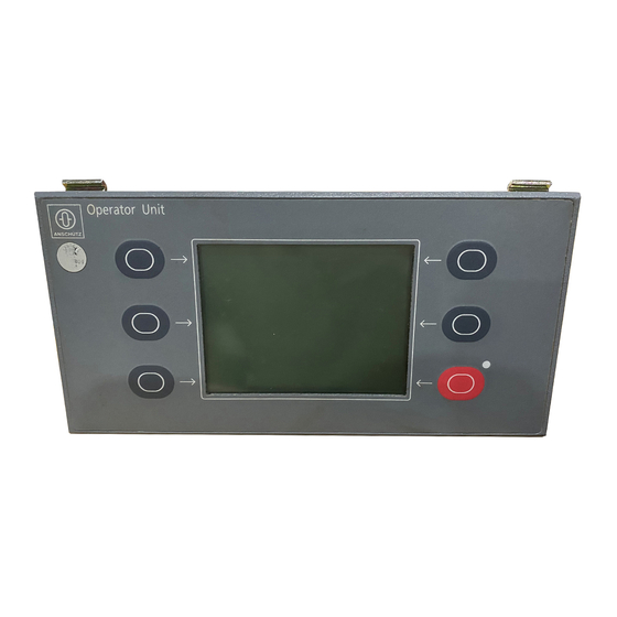
There is no priority control system for connected Operator Units. Each Operator Unit connected to the system has the same priority. The Operator Unit is used to select, use and monitor the navigational devices (sensors). Figure 1: Operator Unit (desk flush mounted) 130 --613 3648/130--613.DOC010102 Edition: March 11, 2005... -
Page 10: The Construction Of The Operator Unit
Operator Unit 130- -613 The Construction of the Operator Unit The Operator Unit is available in two versions -- desk-flush mounted, and with angled fixing bracket. The Operator Unit consists of a casing with a front panel. All the electronics components required are accommodated inside the casing on 2 PCBs. -
Page 11: Principle Of Operation
Operator Unit 130- -613 Operator Unit 1.1.1 Principle of Operation Once a voltage supply is present, the Operator Unit is able to detect every connected item of navigational equipment (sensors) and indicate them on the display unit. Depending on the status of the device, heading information is also now displayed. - Page 12 Operator Unit 130- -613 A two-colour LED is positioned above the red membrane key. This LED indicates alarms and their status. It also serves to indicate when selected data has been transferred to the CAN bus. (the “SET” soft key).
-
Page 13: Can-Bus
Operator Unit 130- -613 Operator Unit 1.1.2 CAN-Bus (CAN = Controller Area Network) CAN bus The CAN bus is a Multi-Master-Bus allowing the connection of all devices and systems regardless of their task and function. This means that any number of devices can be connected. These de- Gyro compass vices must be designed for CAN bus technology. -
Page 14: Technical Data
Mechanical data Length Width Height: 80x192x96 Type of enclosure: IP23 (higher rating with special casing) See also OPERATOR UNIT DIMENSIONAL DRAWING 130 D 613 HP005 1.2.2 Electrical data Supply voltage: 24 V d.c. (9 .. 36 V d.c.) Current consumption: 0.2A) -
Page 15: Operation
Operator Unit 130- -613 Operator Unit Operation Controls and Indicators on the Operator Unit Select GYRO 1 Sensor 068.7° & Menu Contrast Heading Select Gyro 2 067.9° Speed down Gyro 3 068.1° Magnet 069.0° Select Lamp Aut Spd: 08.5Kts Test Aut Lat: 50°05‘... -
Page 16: Setting Into Operation
Operator Unit 130- -613 Setting into Operation The Operator Unit must be configured for CAN bus operation in accordance with the jumper list (see section 8.4.1.2) (the RS422 configuration is a special application only). The Operator Unit switches on as soon as it has a supply of operating voltage. -
Page 17: General Information Regarding The Operation Of The Operator Unit
Operator Unit 130- -613 Operator Unit 2.2.1 General Information regarding the Operation of the Operator Unit The principle of operation is explained on the figure illustrating the display for Gyro1. The meaning and function of each soft key depends on the sensor concerned, and these are explained in more detail in the section referring to the sensor in question. - Page 18 Operator Unit 130- -613 Gyro 1 selected. GYRO 1 Gyro 1 in the heating stage, time to - - - - - -.- -° activate quick settling (3 minutes) is over. Heading (Heating) Gyro 1selected. GYRO 1 Gyro 1 in settling stage (heating 068.7°...
-
Page 19: Changing The Default Settings
Operator Unit 130- -613 Operator Unit 2.2.1.2 Changing the Default Settings Below is a short description (shown at one example) how to change default values. GYRO 1 068.7° Heading Select Down Gyro 2 067.9° Speed Gyro 3 068.1° Magnet 069.0°... -
Page 20: Adjusting Brightness And Contrast
Operator Unit 130- -613 2.2.1.3 Adjusting Brightness and Contrast Select GYRO 1 Sensor 068.7° & Menu Contrast Heading Select Gyro 2 067.9° Speed Down Gyro 3 068.1° Magnet 069.0° Select Lamp Aut Spd: 14.5Kts Test Aut Lat: 46°05‘ Figure 8: Controls and Indicators on the Operator Unit Use the “Dim Up”... -
Page 21: Changing The Current Sensor
Operator Unit 130- -613 Operator Unit 2.2.1.4 Changing the Current Sensor Not each heading receiver is allowed to use heading information from a magnetic compass if selected. Select GYRO 1 Sensor 068.7° & Menu Heading Gyro 2 067.9° Down Gyro 3 068.1°... -
Page 22: Menu Selection
Operator Unit 130- -613 2.2.1.5 Menu selection Use the “Select Sensor & Menu” soft key to select a sub-menu. This sub-menu is used to make settings that require updating relatively rarely, but which are provided for servicing purposes. Sub-menu -- Diff.Alarm (see section 6.1.1 for Gyros and 4.1 for Magnetic compass) The monitoring threshold setting between Gyro1, Gyro2 and Gyro3 GPS (if used) is identical to a Gyro. -
Page 23: Lamp Test
Operator Unit 130- -613 Operator Unit 2.2.1.6 Lamp test A Lamp Test during an alarm is not possible Select GYRO 1 Sensor 068.7° & Menu Contrast Heading Select Gyro 2 067.9° Speed Down Gyro 3 068.1° ° Magnet 069.0 Lamp Select Aut Spd: 14.5Kts... -
Page 24: Alarm And Fault Handling
Operator Unit 130- -613 2.2.2 Alarm and Fault Handling 2.2.2.1 Alarm handling GYRO 1 068.7° Heading Alarm Quit Speed Missing Figure 14: Controls and Indicators on the Operator Unit (alarm is indicated) An alarm is indicated in two ways; the two-colour LED (Figure 14/1) flashes red and the signal transmitter emits an audible signal. - Page 25 Operator Unit 130- -613 Operator Unit There is no need to remedy the cause of the alarm in order to alter values. If the alarm is acknowledged by pressing the “quit” key (Figure 14/2) but the cause of the error is not remedied, the two--colour LED lights red and the audible signal stops.
-
Page 26: Status And Alarm Messages (An Overview)
Operator Unit 130- -613 2.2.2.2 Status and alarm messages (an overview) Displayed Meaning message No connection CAN bus not connected to the Operator Unit No Data on Bus No usable data on the CAN bus. Sensor Error Is displayed if the selected sensor fails, or if the se- lected sensor is no longer connected to the CAN bus. - Page 27 Operator Unit 130- -613 Operator Unit Displayed Meaning message Switched to Mag. Is displayed if the selected Gyro fails, no further Gyro is available, a Magnetic compass is connected and the automatic switch--over function is set (see also section 6.3.2.2).
- Page 28 Operator Unit 130- -613 Displayed Meaning message Not Accepted (Displayed at the bottom line for approx. 2 seconds). Is displayed during pressing “Set” key if the selected value is not accepted or the selected action is not practicable (like manual selection of a faulty sensor) (see also section 6.3.1.4).
-
Page 29: General Error Messages
Operator Unit 130- -613 Operator Unit 2.2.2.3 General Error Messages The CAN bus is designed for redundancy and carries out error processing in the background. “One” CAN bus has failed. Reaction: This error can be detected only by constantly observing the display unit. - Page 30 Operator Unit 130- -613 This error message flashe , and at the same time the LED (Figure 17/1) lights red. OPERATOR UNIT Contrast Panel Down Setup Alarm No Data On Bus Ackn Figure 17: Controls and Indicators on the Operator Unit (No usable data on the CAN bus -- 2nd message) Once the “Alarm Ackn”...
- Page 31 Operator Unit 130- -613 Operator Unit GYRO 1 - - - - - -.- -° No Heading Down Gyro 2 ------.--° Gyro 3 ------.--° Magnet ------.--° Lamp Aut Spd: ----.--Kts Test Aut Lat: ----°----‘ Figure 18: Controls and Indicators on the Operator Unit...
-
Page 32: Warnings
Operator Unit 130- -613 2.2.2.4 Warnings Select GYRO 1 Sensor 068.7° & Menu Warning Contrast (blinking) “(Heater Failure)” Select Gyro 2 067.9° Speed Down Gyro 3 068.1° ° Magnet 069.0 Lamp Select Aut Spd: 14.5Kts Test Aut Lat: 46°05‘ Figure 20: Controls and Indicators on the Operator Unit (with a displayed warning -->... - Page 33 Operator Unit 130- -613 Operator Unit If there are several warning at the same time, the warning with the highest priority is displayed. After the cause of this warning is eliminated, the warning with the next lower priority is displayed.
-
Page 34: Gyrocompass Operation
Operator Unit 130- -613 Gyrocompass Operation Selecting the Sensor Initial status: Gyro 1 is selected as the navigational sensor. Select GYRO 1 Sensor 068.7° & Menu Heading Gyro 2 067.9° Down Gyro 3 068.9° Magnet 069.0° Menu EXIT Figure 22: Controls and Indicators on the Operator Unit (Gyro 1 sensor is selected) Press the “Select Sensor &... -
Page 35: The Heading Display
Operator Unit 130- -613 Operator Unit 3.1.1 The HEADING display Indication of the compass heading output from Gyro2 Select GYRO 2 Sensor 067.9° & Menu Contrast Heading Select Gyro 068.7° Down Speed Gyro 068.6° Magnet 069.0° Select Lamp Aut Spd: 08.5kn... -
Page 36: (Heating Stage And Settling Stage)
Operator Unit 130- -613 3.1.1.1 Heading indication from gyro system after switching on (Heating stage and settling stage) Note: During the first 3 minutes after switching--on (heating stage), it is possible to activate the quick settling function (see section 3.4). - Page 37 Operator Unit 130- -613 Operator Unit The gyro heading may be used to a certain extent during the settling stage. However you should be aware that there will still be fairly high error margins. The gyro system is settled after a period of 4 hours and will then indicate the gyro heading to the specified precision.
-
Page 38: Selecting Man Speed / Aut Speed
Operator Unit 130- -613 Selecting Man Speed / Aut Speed If an automatic speed source (LOG) is available “Aut Spd” is selected as the default setting. Select GYRO 2 Sensor 067.9° & Menu Contrast Heading Select Gyro 1 068.7° Down... - Page 39 Operator Unit 130- -613 Operator Unit Switching from “Aut Spd” ⇒”Man Spd” The “Select Speed” key (Figure 29/1) changes its functions when a change is made. It alters each time the setting is changed from “Aut Spd” to “Man Spd”...
- Page 40 Operator Unit 130- -613 Entering speed values manually GYRO 2 067.9° Heading Select Down Gyro 1 068.7° Speed Gyro 3 068.9° Magnet 069.0° Man Spd: 10.2 Figure 30: Controls and Indicators on the Operator Unit (Man Spd selected) Press the “Select Speed” key (Figure 30/1).
-
Page 41: Selecting Man Lat And Aut Lat
Operator Unit 130- -613 Operator Unit Comments regarding Speed Error Correction Speed error is a physical deviation from the steering heading indicated on the gyro compass (compass heading) from the true heading (chart heading). The speed error depends on the speed of the ship, the heading it is steering and the latitude. - Page 42 Operator Unit 130- -613 Selecting Man Lat and Auto Lat The “Select Lat” key (Figure 31/1) changes its functions when a change is made. It alters each time the setting is changed from “Aut Lat” to “Man Lat”. GYRO 2 067.9°...
- Page 43 Operator Unit 130- -613 Operator Unit Entering latitude values manually GYRO 2 067.9° Heading Gyro 1 068.7° Down Gyro 3 068.9° Magnet 069.0° Select Man Lat: 50°50‘ Figure 33: Controls and Indicators on the Operator Unit (Man Lat selected) Press the “Select Lat” key (Figure 33/1).
-
Page 44: Activation Of The Quick Settling Function
Operator Unit 130- -613 Activation of the Quick Settling function The “Quick Settling” function reduces the time the compass requires to settle from approximately 4 hours to approximately one hour The most recent heading is stored when the gyro compass is switch off. When it is switched on the compass uses that value to make a default setting so that the settling time is reduced. -
Page 45: Quick Settling Activation Of Selected Gyro
Operator Unit 130- -613 Operator Unit 3.4.1 Quick Settling activation of selected gyro After switching on of the selected compass the possibility to activate the Quick Settling function is displayed. (Figure 34). Select GYRO 1 Heating stage, Sensor - - - - - -.- -°... - Page 46 Operator Unit 130- -613 Basic Menu ----> Selected line: “Menu” ----> Display “Menu” Gyro 1 Select - - - - - -.- -° Menu (QS--possible) Diff--Alarm Down Panel set up Service Quick--Settling EXIT Figure 36: Controls and Indicators on the Operator Unit...
- Page 47 Operator Unit 130- -613 Operator Unit After confirming by “SET” the activated Quick Settling function for the selected gyro is displayed by “Gyro 1 QS Set” (Figure 37). After selection of “Exit” the basic menu is displayed (Figure 38). Select...
-
Page 48: Quick Settling Activation Of Not Selected Gyro
Operator Unit 130- -613 3.4.2 Quick Settling activation of not selected gyro Select GYRO 1 Heating stage, Sensor 068.9° no possibility for & Menu Quick Settling (3 minutes are over) Contrast Heading Select Gyro 2 QS possib Down Speed Gyro 3 ------.--°... - Page 49 Operator Unit 130- -613 Operator Unit After confirming by “SET” the activated Quick Settling function for the selected gyro is displayed by “Gyro 2 QS Set” (Figure 40). After selection of “Exit” the basic menu is displayed (Figure 41). Select...
-
Page 50: Magnetic Compass Operation
Operator Unit 130- -613 Magnetic Compass Operation It has to paid attention that not every heading receiver is allowed to be connected to a heading from a magnetic compass. Initial status: The magnetic compass is selected as the sensor providing the heading. -
Page 51: Display/Amend Alarm Threshold For Gyro/Magnet
Operator Unit 130- -613 Operator Unit Display/amend alarm threshold for Gyro/Magnet (see also section 6.1) The Diff G/M function makes it possible to monitor the selected gyro compass (here Gyro1) using data from the magnet compass. Both heading values are monitored for difference. - Page 52 Operator Unit 130- -613 Select “Diff--G/M*: 03.0° on the “Diff-Alarm” sub--menu by pressing “Set” (Figure 45/3) (LED Figure 45/4 flashing) and then alter it by pressing “Up”/”Down” (Figure 45/1 and 2). the display “Diff--G/M” can also mean: difference between GPS and magnet.
-
Page 53: Display And Alter Variation/Deviation
Operator Unit 130- -613 Operator Unit 4.1.1 Display and alter Variation/Deviation Deviation A heading display from a compass may be affected by permanent magnetic parts of steel, lines with direct current flow or magnetic soft iron parts in that manner, that the heading information is faulty. -
Page 54: Single Value Input
Operator Unit 130- -613 4.1.1.1 Single value input Initial status: The magnetic compass is selected as the navigational sensor. Select Magnet Sensor 069.0° & Menu Contrast Heading Devi-- Gyro 1 068.7° Down ation Gyro 3 068.9° Magnet 069.0° ° Deviation: +4.5... - Page 55 Operator Unit 130- -613 Operator Unit Deviation (deviation in relation to the ship) Select the deviation input field by pressing the “Deviation” key (Figure 46/1) Alter the values (deviation) by pressing the “Up” or “Down” keys. (Figure 47/2 or 3).
-
Page 56: Applying Or Amending A Deviation Table
Operator Unit 130- -613 4.1.1.2 Applying or amending a deviation table Select Magnet Sensor 069.0° & Menu Heading Gyro 1 068.7° Down Gyro 2 067.9° Gyro 3 067.9° Menu EXIT Figure 48: Controls and Indicators on the Operator Unit (Line “Menu” selected) Select the line “Menu”... - Page 57 Operator Unit 130- -613 Operator Unit Note: Value ------.--° --> if there is a value before and after this not--set--value, an internal value is calcualted value (by interpolation) and displayed (see Figure 3). But the not--set--value in the deviation table is still ------.--°.
-
Page 58: Operation Of Satellite Compass Std 21 (Gps)
Operator Unit 130- -613 Operation of Satellite Compass STD 21 (GPS) Within a navigation system, which is based on a Gyro compass STD 22, it can connect except a magnetic compass a Satellite Compass STD 21 (GPS) too. This compass is displayed as GPS. -
Page 59: Adjustment Of Additional Operation Modes With Service Menu
Operator Unit 130- -613 Operator Unit Adjustment of additional operation modes with the service menu After selection of the menu line “Menu” below mentioned submenus are displayed to select other operational modes: -- Diff--Alarm (Difference Alarm) (see section 6.1) -- Panel Setup (see section 6.2) -- Service (see section 6.3) - Page 60 Operator Unit 130- -613 Sensors Comparison in the system Gyro 1/ The selected sensor is compared with the not selected sensor. Gyro 2 Gyro/ The selected sensor is compared with the not selected sensor. Magnet Gyro 1/ Gyro 1 selected: Gyro 2/ -- Comparison Gyro 1 to Gyro 2 and to Magnet.
- Page 61 Operator Unit 130- -613 Operator Unit Sensors Comparison in the system Gyro/ The selected sensor is compared with the not selected sensor. GPS/ The selected sensor is compared with the not selected sensor. Magnet Gyro 1/ Gyro 1 selected: GPS/ -- Comparison Gyro 1 to GPS and to Magnet.
-
Page 62: G1/G2/G3 Difference Alarm
Operator Unit 130- -613 6.1.1 G1/G2/G3 or GPS difference alarm This alarm is generated, if one of the gyros shows a heading value (in comparison to the others -- if there are), which is more than the set threshold. Only one level (threshold) for all connected gyros can be set and adjusted. - Page 63 Operator Unit 130- -613 Operator Unit Magnet Select 069.0° Menu Heading Diff-Alarm Down Panel Setup Service EXIT Figure 53: Controls and Indicators on the Operator Unit (“Diff-Alarm” line selected) You can select “Diff--G/G: 03.0°” on the “Diff-Alarm” sub-menu by pressing “Set”...
-
Page 64: Panel Setup
Operator Unit 130- -613 Panel Setup Software version With this sub--menu the volume of the alarm buzzer can be adjusted and the software version of the Operation Unit is displayed. Select GYRO 1 Sensor 069.0° & Menu Heading Gyro 2 068.7°... - Page 65 Operator Unit 130- -613 Operator Unit Test Panel Setup Select Horn Volume 1 Volume 2 Volume 3 Volume 4 Softw.--Version: 130--613P01.E001. Exit Figure 57: Controls and Indicators on the Operator Unit (Sub--menu “Panel Setup” selected) NOTE: The software version shown in must not be the actual version By operating the softkeys“Select”...
-
Page 66: Service Mode
Operator Unit 130- -613 Service Mode This sub--menu is divided into two pages and contains: Page 1 Page 2 Speed Source (not for DV bus application) Auto Heading Heading Uncorrected DV bus Rate of Turn Deviation Table* GPS Setup** Gyro Data*... -
Page 67: Service Mode
Operator Unit 130- -613 Operator Unit 6.3.1 Service Mode Page 1 Service (page 1) Select Menu Speed Source Heading uncorr. Rate of Turn Down GPS Setup CAN--Devices Next page Exit Figure 59: Controls and Indicators on the Operator Unit ”Service (page 1)” menu selected Each service function has a time--out counter of 60 seconds. -
Page 68: Can Bus Adressees
Operator Unit 130- -613 6.3.1.1 CAN- -Bus Addressees With this sub--menu all addresses of connected devices at the CAN bus can be displayed. By this it is not necessary to open all devices in case of an enlargement of the system. -
Page 69: Heading Without Correction Values
Operator Unit 130- -613 Operator Unit 6.3.1.2 Heading without correction values With this function the heading values without correction values of the gyros (as there are speed error correction, alignment error) are displayed. Inputs and/or changes are not possible in with this function. -
Page 70: Damping Of The Rate Of Turn
Operator Unit 130- -613 6.3.1.3 Damping of the Rate of Turn With this function it is possible to damp the influence of the seastate to the Rate of Turn. This Damping only acts to analogue RoT--devices. RoT--devices which are controlled via NMEA--telegrams are controlled with the min. - Page 71 Operator Unit 130- -613 Operator Unit The Rate of Turn can not be adjusted, displayed only. The scaling of the Rate of Turn has to be carried out in the Distribution Unit The line “Rate Gyro” displays the Rate of Turn of an external Rate of Turn sensor connected at the Distribution Unit.
-
Page 72: Speed Source
Operator Unit 130- -613 6.3.1.4 Speed Source With this function the source of the speed resp. the kind of the speed, which is necessary for the speed error correction, can be selected. This function can not be adjusted in DV--bus operation,... -
Page 73: Gps Setup
Operator Unit 130- -613 Operator Unit Meaning of abbreviations and add--on : Velocity Heading through Water Available connected but not selected Velocity through Ground Selected connected and selected VBW Wtr. Velocity below Wate Not Available possible, but actually not connected... -
Page 74: Service Mode
Operator Unit 130- -613 6.3.2 Service Mode Page 2 Service (page 1) Select Menu Speed Source Heading uncorr. Rate of Turn Down GPS Setup CAN--Devices Next Page Exit Figure 65: Controls and Indicators on the Operator Unit ”Service (page 1)” menu selected With “Select Menu”... -
Page 75: Dv--Bus Application
Operator Unit 130- -613 Operator Unit 6.3.2.1 DV- -bus application With this function it is to be adjusted, if the Distribution Unit 138--118 (see manual no.: 3647) is connected to a DV--bus and if so the respective address of the Distribution Unit on the DV--bus is set. - Page 76 Operator Unit 130- -613 Select “Service” line ----> select “DV--Bus” line ----> select function “Address”. With this function a DV--bud address is selected. By operating the softkeys “Up” or “Down” addresses from 001 up to 015 can be adjusted. The address for the distribution unit has never be twice in the DV--bus...
-
Page 77: Auto Heading Switch--Over
Operator Unit 130- -613 Operator Unit 6.3.2.2 Auto Heading Switch- -over This function is to establish if, in case of a selected heading sensor fails an automatic switch--over to the next heading sensor in function, takes place. It is to select if a change--over to the next Gyro, GPS or to a Magnetic compass should be performed. - Page 78 Operator Unit 130- -613 Auto Heading to Gyro to TMC Set Values Back Exit Service Timeout in: 50s Without GPS Auto Heading to Gyro/GPS Y to TMC Set Values Back Exit Service Timeout in: 50s With GPS Figure 71: Controls and Indicators on the Operator Unit (Function “Auto Heading”)
- Page 79 Operator Unit 130- -613 Operator Unit Sensors Alarm message (basic is the selected sensor) Gyro 1 Switched to Gy 2 Switched to Gy 2 Gyro 2 Gyro 1 Switched to Mag Switched to Mag Gyro 1 Switched to Gy 2...
-
Page 80: Deviation Table
Operator Unit 130- -613 With selection of line “to Gyro/GPS” to Yes (Y) and confirmation with selection of line “Set Values” it is to switch--over automatically to the next gyro in function (depending on the CAN--bus address) if the selected gyro fails. -
Page 81: Gyro Data
Operator Unit 130- -613 Operator Unit 6.3.2.4 Gyro Data With this sub--menu the essential operating data of all connected Gyros (max. three) are displayed. Select line “Menu” with the softkeys “Select Sensor & Menu” and ”Set”. Select line “Service” with the softkeys “Select Menu” and “Set” in the following display. - Page 82 Operator Unit 130- -613 With softkey “Select” one of the lines “Set Service Timeout to 120s” or “Exit” can be selected. By operating the softkey “Set” and selected line “Set Service Time out to 120s” the internal counter is set to 120 seconds again.
-
Page 83: Software Versions
Operator Unit 130- -613 Operator Unit 6.3.2.5 Software Versions With this submenu the software status of all processor program--memories of PCB of the connected Gyros (max. three) and of the Distribution unit are displayed. SW Versions Select Gy1/15 Gy2/16 110--233.P01.E10.00 P00.E00.00... - Page 84 Operator Unit 130- -613 With softkey “Select” one of the lines “Set Service Timeout to 120s” or “Exit” can be selected. By operating the softkey “Set” and selected line “Set Service Time out to 120s” the internal counter is set to 120 seconds again.
-
Page 85: Switching Off The Operator Unit
Operator Unit 130- -613 Operator Unit Switching Off the Operator Unit The equipment is switched off when the voltage supply to the operator unit is switched off. Even if the equipment in question is installed as the “end device” on a CAN bus application, the operation of the other connected devices will not be affected. -
Page 86: Operator Unit Maintenance And Repair
Operator Unit 130- -613 Operator Unit maintenance and repair The Operator Unit is maintenance-free. If necessary wipe the display unit clean with a dry cloth. Repair: In case of malfunction, the Operator Unit has to be replaced complete . Operation during a replacement can only be performed when the CAN--bus is terminated. -
Page 87: Installation
Installation Assembly The Operator Unit must be assembled with the aid of dimensional drawing 130--613 HP005 either on an angled fixing bracket or desk-flush mounted. Make sure that the installation is resistant to sea-water. Overview of switches, jumpers and plugs... -
Page 88: Setting The Device Address
Operator Unit 130- -613 Setting the device address Use the two hexadecimal switches to set the device address for the Operator Unit. The device address is set by the manufacturer to 01 decimal. To change this setting is only necessary if another Operator Unit should be installed. - Page 89 Operator Unit 130- -613 Operator Unit Hexadecimal switch B23 (switch position 1 to 9) Hexadecimal switch B24 (switch position 0 to F) always set to 0 for the Operator Unit Figure 75: Setting the device address 3648/130--613.DOC010102 Edition: March 11, 2005...
-
Page 90: Making The Cable Connections
Operator Unit 130- -613 Making the cable connections 8.4.1 General information about establishing on-board wiring Caution! When establishing cable connections ensure that the cables are disconnected from the power supply. It is essential to ensure that all cables are disconnected from the power supply, if necessary measure the voltage beforehand and/or disconnect the relevant distributor. - Page 91 Operator Unit 130- -613 Operator Unit -- Connect the plug as shown in Figure 78 or Figure 79. -- Plug the plug into the corresponding counter plug. Figure 77: Example of a CAN1 bus -- CAN2 bus connection (the Operator Unit is not the end device) 3648/130--613.DOC010102...
-
Page 92: Connections To The Plug Connections
Operator Unit 130- -613 8.4.1.1 Connections to the plug connections Connection to supply voltage Cable no.: WN219- -401- -3.0 Connector pin assignment: White +9V to 36V Brown Black Screen Plug B2 Plug B1 Plug B7 CAN 2 CAN 1 Voltage supply... - Page 93 Operator Unit 130- -613 Operator Unit OPTION (currently not used) Pin: 1 2 3 Pin: 1 2 3 Plug B2 Plug B1 RS422 connection RS422 RS422 Plug B1 = Transmit Receive Transmit Plug B2 = Receive 1 RX-- 1 TX--...
-
Page 94: Plugging In The Jumpers
Operator Unit 130- -613 8.4.1.2 Plugging in the jumpers Jumper B15 B16 Figure 80: Plugging in the jumpers Jumper Default Function 3- -2- -1 Default Plug B1 -- CAN 1 Plug B1 -- RS422 Plug B1 -- CAN 1 Default...
Need help?
Do you have a question about the 130 and is the answer not in the manual?
Questions and answers