Table of Contents
Advertisement
Quick Links
AN2810
Application note
6-row 85 mA LED driver with boost
converter for LCD panel backlighting
Introduction
The LED7707 LED driver from STMicroelectronics consists of a high-efficiency monolithic
boost converter and six controlled current generators (rows), specifically designed to supply
LED arrays used in the backlighting of LCD panels. The device can manage an output
voltage up to 36 V (i.e. ten white-LEDs per row). The generators can be externally
programmed to sink up to 85 mA and can be dimmed via a PWM signal (1% of minimum
dimming duty-cycle at 1 kHz can be managed). The device allows detection and
management of open and shorted LED faults, and permits unused rows to be left floating.
Basic protections (output overvoltage, internal MOSFET overcurrent and thermal shutdown)
are provided.
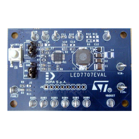
Figure 1.
LED7707 demonstration board
May 2009
Doc ID 14893 Rev 1
1/17
www.st.com
Advertisement
Table of Contents

Related Manuals for STMicroelectronics LED7707


Summary of Contents for STMicroelectronics LED7707
- Page 1 LCD panel backlighting Introduction The LED7707 LED driver from STMicroelectronics consists of a high-efficiency monolithic boost converter and six controlled current generators (rows), specifically designed to supply LED arrays used in the backlighting of LCD panels. The device can manage an output voltage up to 36 V (i.e.
-
Page 2: Table Of Contents
LED7707 main features ........ - Page 3 LED7707 demonstration board schematic ........
-
Page 4: Led7707 Main Features
LED7707 main features AN2810 LED7707 main features Boost section ● 4.5 V to 36 V input voltage range ● Internal power MOSFET ● Internal +5 V LDO for device supply ● Up to 36 V output voltage ● Constant frequency peak current-mode control ●... -
Page 5: Led7707 Demonstration Board
AN2810 LED7707 demonstration board LED7707 demonstration board The LED7707 demonstration board has been designed to manage six strings of 8 to 10 white LEDs each. Table 1 summarizes the board features and Figure 2 shows the LED7707 demonstration board schematic. The input voltage range is limited to 32 V because of the 35 V rated input capacitor. -
Page 6: Component List
68 µH, 75 mH, 5.8 A 7x7mm XPL7030-682ML Coilcraft 6.8 µH Schottky, 40 V, 1 A DO216-AA STPS1L40M STPS1L40M Red LED, 3 mA SMD 0603 Standard Signal Schottky SOD-523 BAS69 N.M. Integrated circuit QFN4x4 LED7707 LED7707 PCB pad jumper 6/17 Doc ID 14893 Rev 1... -
Page 7: Component Assembly And Layout
AN2810 Component assembly and layout Table 2. LED7706 demonstration board component list (continued) Componen Description Package Part-number Value Header 8 SIL 8 Standard SW1, SW2 Jumper 3 SIL 3 Standard Pushbutton 6x6mm FSM4JSMAT TYCO Component assembly and layout Figure 3. Top side component placement Figure 4. -
Page 8: O Interface
Signal generators for PWM dimming and synchronization clock (optional) Configuration The LED7707 demonstration board allows the user to choose the desired mode of operation using the SW1 and SW2 selectors (refer to the configuration description in the following paragraphs). A red LED is connected to the FAULT pin to easily monitor its status; if this option is not required, the monitor LED can be disconnected opening the J2 jumper. -
Page 9: Sw2 Fault Management Mode (Mode Pin)
AN2810 Configuration If SW1 is in the “up” position, the switching frequency is given by: Equation 1 ⋅ 2.5 R Figure 5. SW1 (F ) setting The R5 resistor is set to 330 kΩ (F = 825 kHz) and can be changed by the user. SW2 fault management mode (MODE pin) The SW2 selector is used to connect the MODE to AVCC or ground. -
Page 10: Sw3 Enable Function
Configuration AN2810 Table 4. Fault management summary Fault MODE to GND MODE to VCC Fault pin HIGH Internal MOSFET overcurrent Power MOSFET turned off FAULT pin LOW Output overvoltage Power MOSFET turned off (hysteretic regulation) FAULT pin LOW. Device turned off. Thermal shutdown °... -
Page 11: Test Setup
An appropriate white LED array is required as a load to correctly evaluate the LED7706. Figure 7 shows a possible assembly of the LED7707 with a WLED test board. This demonstration board includes 60 white LEDs (150 mA), switches, jumpers and test points which can be used to easily perform functional testing of the LED7707. -
Page 12: Getting Started
Working in an ESD-protected environment is highly recommended. Check all wrist straps and ESD mat earth connections before handling the LED7707 board Connect the power supply to the LED7707 board and insert the A-meter as shown in Figure 8. Connect a V-meter between VBOOST and ground to monitor the output... -
Page 13: Open And Shorted Wleds Fault Testing
Disconnect the rows in sequence and compare the behavior of the LED7707 to Table 4 Restore all row connections and press the SW3 pushbutton on the LED7707 board to reset the device Short one or more WLEDs and compare the LED7707 behavior to... -
Page 14: Efficiency Measurements
Getting started AN2810 Figure 9. LED7707 synchronization setup 700kHz – 30% 700kHz – 30% 700kHz – 30% Clock Generator Clock Generator Clock Generator PWM Generator PWM Generator SYNC SYNC VIN- VIN- 4.5V – 32V @ 2A 4.5V – 32V @ 2A... - Page 15 AN2810 Getting started channels are in parallel, a single string of 700 mA-rated LEDs is required as load (Figure 10). Figure 10. Efficiency measurement setup PWM Generator PWM Generator 4.5V – 32V @ 2A 4.5V – 32V @ 2A Power Supply Power Supply VIN- VIN-...
-
Page 16: Revision History
Revision history AN2810 Revision history Table 5. Document revision history Date Revision Changes 26-May-2009 Initial release 16/17 Doc ID 14893 Rev 1... - Page 17 Please Read Carefully: Information in this document is provided solely in connection with ST products. STMicroelectronics NV and its subsidiaries (“ST”) reserve the right to make changes, corrections, modifications or improvements, to this document, and the products and services described herein at any time, without notice.
Need help?
Do you have a question about the LED7707 and is the answer not in the manual?
Questions and answers