Table of Contents
Advertisement
Quick Links
Advertisement
Table of Contents

Related Manuals for IEI Technology PUZZLE-IN001 Series


Summary of Contents for IEI Technology PUZZLE-IN001 Series
- Page 1 PUZZLE-IN001 MODEL: PUZZLE-IN001 1U Network Appliance with 8th Gen. Intel® Core™ i3, Pentium®, Celeron® and Intel® Xeon® E Processor, DDR4, Eight GbE Ports, Two PCIe Slots, M.2, PCIe Mini, Redundant PSU, Rack Mount, and RoHS Compliant User Manual Page 1 Rev.
- Page 2 PUZZLE-IN001 Revision Date Version Changes September 1, 2020 1.03 Added Section 3.4 CPU Installation (PUZZLE-IN001-R Only) Added username and password information for system login in Section 3.13 Power-On Procedure Added Section 3.11.1 Enable Console Port When Booting Modified Section 3.12 Rack Mount Modified storage temperature November 19, 2019 1.02...
- Page 3 PUZZLE-IN001 Copyright COPYRIGHT NOTICE The information in this document is subject to change without prior notice in order to improve reliability, design and function and does not represent a commitment on the part of the manufacturer. In no event will the manufacturer be liable for direct, indirect, special, incidental, or consequential damages arising out of the use or inability to use the product or documentation, even if advised of the possibility of such damages.
- Page 4 PUZZLE-IN001 Manual Conventions WARNING Warnings appear where overlooked details may cause damage to the equipment or result in personal injury. Warnings should be taken seriously. CAUTION Cautionary messages should be heeded to help reduce the chance of losing data or damaging the product. NOTE These messages inform the reader of essential but non-critical information.
-
Page 5: Table Of Contents
PUZZLE-IN001 Table of Contents 1 INTRODUCTION ......................11 1.1 O ........................ 12 VERVIEW 1.2 M ....................13 ODEL ARIATIONS 1.3 F ......................... 13 EATURES 1.4 F ......................14 RONT ANEL 1.5 R ......................14 ANEL 1.6 T ..................15 ECHNICAL PECIFICATIONS 1.6.1 Expansion Slot Block Diagram ................ - Page 6 PUZZLE-IN001 3.11.1 Enable Console Port When Booting............... 43 3.12 R ......................46 OUNT 3.13 P ..................47 OWER ROCEDURE 3.14 A ....................48 VAILABLE RIVERS 3.14.1 Driver Download ................... 49 3.15 M ....................... 50 AINTENANCE 3.15.1 Power Supply Unit Replacement ..............51 3.15.2 Jumper Settings ....................
- Page 7 PUZZLE-IN001 4.4.2.1 PCI Express Configuration ............... 76 4.4.2.2 SATA and RST Configuration ..............78 4.4.2.3 Network Configuration (Bypass Setting) ..........80 4.5 S ......................... 81 ECURITY 4.6 B ........................82 4.7 S & E ......................84 5 INTERFACE CONNECTORS ................... 85 5.1 P ..............
- Page 8 PUZZLE-IN001 B.1.3 Product Disposal ................... 107 B.2 M ............108 AINTENANCE AND LEANING RECAUTIONS B.2.1 Maintenance and Cleaning ................108 B.2.2 Cleaning Tools ....................108 C ERROR BEEP CODE ....................110 C.1 PEI B ....................111 ODES C.2 DXE B ....................
- Page 9 PUZZLE-IN001 List of Figures Figure 1-1: PUZZLE-IN001 Series ....................12 Figure 1-2: PUZZLE-IN001 Front Panel..................14 Figure 1-3: PUZZLE-IN001 Rear Panel ..................14 Figure 1-4: Expansion Slot Block Diagram ................17 Figure 1-5: Physical Dimensions (millimeters) ................18 Figure 3-1: Top Cover Removal ....................25 Figure 3-2: DIMM Slot Locations ....................26 Figure 3-3: Disengage the CPU Socket Load Lever ..............27...
- Page 10 PUZZLE-IN001 List of Tables Table 1-1: PUZZLE-IN001 Model Variations ................13 Table 1-2: Technical Specifications ....................16 Table 3-1: LAN Pinouts ........................42 Table 3-2: RJ-45 Ethernet Connector LEDs ................42 Table 3-3: RJ-45 Serial Port Pinouts ...................43 Table 3-4: Flash Descriptor Security Override Jumper Settings ..........53 Table 4-1: BIOS Navigation Keys ....................57 Table 5-1: Peripheral Interface Connectors ................87 Table 5-2: ATX Power Connector Pinouts..................88...
-
Page 11: Introduction
PUZZLE-IN001 Chapter Introduction Page 11... -
Page 12: Overview
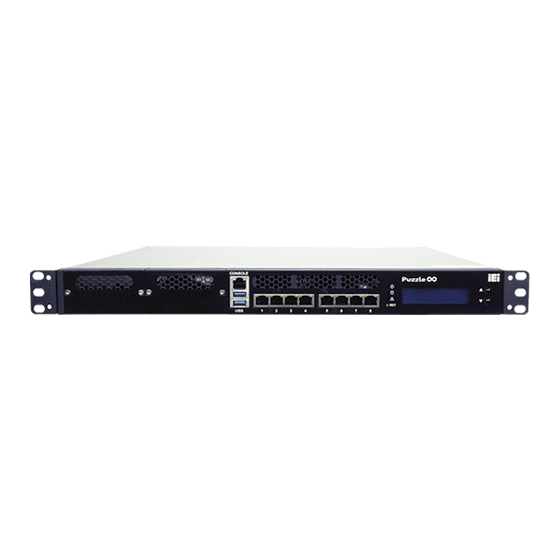
PUZZLE-IN001 1.1 Overview Figure 1-1: PUZZLE-IN001 Series The PUZZLE-IN001 is a 1 U network appliance series powered by the 8th generation ® Intel® Xeon , Core™ i3, Pentium® or Celeron® processor. It is optimized to host VNFs (Virtual Network Functions) and is ideal for SD-WAN. -
Page 13: Model Variations
PUZZLE-IN001 1.2 Model Variations The model variations of the PUZZLE-IN001 are listed below. PUZZLE-IN001 Memory ® -i3T/R Intel Core™ i3-8100T ® -i3T/16G/R Intel Core™ i3-8100T 16 GB 256 GB ® ® -XE/R Intel Xeon E-2136 ® ® -XE/16G/R Intel Xeon E-2136 16 GB 256 GB... -
Page 14: Front Panel
PUZZLE-IN001 1.4 Front Panel The overview of the front panel is shown in Figure 1-2. Figure 1-2: PUZZLE-IN001 Front Panel The states of the LED indicators located on the front panel are listed below. The system is turned off. Power LED Blue The system is turned on. -
Page 15: Technical Specifications
PUZZLE-IN001 1.6 Technical Specifications The PUZZLE-IN001 technical specifications are listed in Table 1-2. System Form Factor ® ® ® ® CPU (SoC) gen Intel Xeon , Core™ i3, Pentium or Celeron processor ® XE SKU: 8 gen Intel Xeon® E-2136 processor ®... -
Page 16: Table 1-2: Technical Specifications
PUZZLE-IN001 Indicator LCM (with two control buttons) Power status (blue) HDD status (green) Alert LED (programmable, red) Switch/Button Power switch (rear panel) Reset button (front panel) 1 x TPM 2.0 (2x10 pin header) Antenna Connector 1 x Knockout hole for antenna connector Power Power Input 100 V ~ 240 V, 5 A ~ 2.5 A, 60 Hz ~ 50 Hz... -
Page 17: Expansion Slot Block Diagram
PUZZLE-IN001 1.6.1 Expansion Slot Block Diagram The block diagram of the expansion slots is shown below: Figure 1-4: Expansion Slot Block Diagram 1.7 Dimensions Page 17... -
Page 18: Figure 1-5: Physical Dimensions (Millimeters)
PUZZLE-IN001 The physical dimensions are shown below: Figure 1-5: Physical Dimensions (millimeters) Page 18... -
Page 19: Unpacking
PUZZLE-IN001 Chapter Unpacking Page 19... -
Page 20: Anti-Static Precautions
PUZZLE-IN001 2.1 Anti-static Precautions WARNING: Failure to take ESD precautions during installation may result in permanent damage to the PUZZLE-IN001 and severe injury to the user. Electrostatic discharge (ESD) can cause serious damage to electronic components, including the PUZZLE-IN001. Dry climates are especially susceptible to ESD. It is therefore critical that whenever the PUZZLE-IN001 or any other electrical component is handled, the following anti-static precautions are strictly adhered to. -
Page 21: Packing List
PUZZLE-IN001 2.3 Packing List NOTE: If some of the components listed in the checklist below are missing, please do not proceed with the installation. Contact the IEI reseller or vendor you purchased the PUZZLE-IN001 from or contact an IEI sales representative directly. -
Page 22: Optional Items
PUZZLE-IN001 2.4 Optional Items The following table lists the optional items that can be purchased separately. Optional Item Image Sliding rails for rack mount (P/N: RAIL-B02) USB to console cable (P/N: 32013-004000-100-RS) RS-232 to console cable (P/N: 32005-005100-100-RS) 20-pin Infineon TPM 2.0 module, software management tool, firmware v5.5 (P/N: TPM-IN02-R20) CPU heatsink (80W) -
Page 23: Installation
PUZZLE-IN001 Chapter Installation Page 23... -
Page 24: Installation Precautions
PUZZLE-IN001 3.1 Installation Precautions CAUTION! The PUZZLE-IN001 series has more than one power supply connection point. To reduce the risk of electric shock, disconnect all power sources before installing or servicing the PUZZLE-IN001 series. During installation, be aware of the precautions below: ... -
Page 25: Top Cover Removal
PUZZLE-IN001 3.2 Top Cover Removal WARNING: Never open the equipment. For safety reasons, the equipment should be opened only by qualified skilled person. Before installing or maintaining the internal components, the top cover must be removed from the PUZZLE-IN001. Follow the steps below to complete the task. Step 1: Remove the five retention screws indicated in Figure 3-1. -
Page 26: Dimm Installation
PUZZLE-IN001 3.3 DIMM Installation CAUTION: For dual channel configuration, always install two identical memory modules that feature the same capacity, timings, voltage, number of ranks and the same brand. To install the DIMM module, please follow the steps below. Step 1: Remove the top cover from the PUZZLE-IN001. -
Page 27: Cpu Installation (Puzzle-In001-R Only)
PUZZLE-IN001 Step 4: Align the DIMM so the notch on the memory lines up with the notch on the memory socket. Step 5: Once aligned, press down until the DIMM is properly seated. Clip the two handles into place. To remove a DIMM, push both handles outward. The memory module is ejected by a mechanism in the socket.Step 0: 3.4 CPU Installation (PUZZLE-IN001-R Only) -
Page 28: Figure 3-4: Remove Protective Cover
PUZZLE-IN001 Step 2: Open the socket and remove the protective cover. The black protective cover can be removed by pulling up on the tab labeled "Remove". See Figure 3-4. Figure 3-4: Remove Protective Cover Step 3: Inspect the CPU socket. Make sure there are no bent pins and make sure the socket contacts are free of foreign material. -
Page 29: Figure 3-5: Insert The Socket Lga1155 Cpu
PUZZLE-IN001 Figure 3-5: Insert the Socket LGA1155 CPU Step 8: Close the CPU socket. Close the load plate and pull the load lever back a little to have the load plate be able to secure to the knob. Engage the load lever by pushing it back to its original position (Figure 3-6). -
Page 30: Cpu Heatsink Installation (Puzzle-In001-R Only)
PUZZLE-IN001 3.4.1 CPU Heatsink Installation (PUZZLE-IN001-R Only) WARNING: Do not wipe off (accidentally or otherwise) the pre-sprayed layer of thermal paste on the bottom of the heat sink. The thermal paste between the CPU and the heat sink is important for optimum heat dissipation. A CPU heatsink must be installed in the PUZZLE-IN001-R after the CPU installation. -
Page 31: Hdd Installation
PUZZLE-IN001 Figure 3-7: CPU Heatsink Installation 3.5 HDD Installation The PUZZLE-IN001 allows installation of two 2.5" SATA HDD/SSD. To install HDDs into the system, please follow the steps below. Step 1: Remove the top cover from the PUZZLE-IN001. Please follow the instruction described in Section 3.2. -
Page 32: Figure 3-8: Hdd Bracket Retention Screws
PUZZLE-IN001 Figure 3-8: HDD Bracket Retention Screws Step 3: Insert an HDD into the bracket until the HDD is properly connected to the SATA connector. Secure the HDD with four retention screws (M3*4). See Figure 3-10. Figure 3-9: Secure HDD to the Bracket Step 4: Re-connect the SATA connector module to the motherboard. -
Page 33: Pcie Expansion Card Installation
PUZZLE-IN001 bracket (Figure 3-10). Secure the bracket to the chassis with three screws removed previously. Figure 3-10: HDD Installation Step 5: Re-install and secure the top cover to the system. 3.6 PCIe Expansion Card Installation The PUZZLE-IN001 allows installation of one PCIe x4 card and one PCIe x8 card. To install a PCIe expansion card, please follow the steps below. -
Page 34: Figure 3-11: Expansion Slot Module Retention Screws
PUZZLE-IN001 Figure 3-11: Expansion Slot Module Retention Screws Step 3: Push the expansion slot module with strength to disconnect the module from the edge connector of the motherboard. Figure 3-12: Disconnect the Expansion Slot Module Page 34... -
Page 35: Figure 3-13: Blank Bracket Screw
PUZZLE-IN001 Step 4: Remove the blank bracket panel that aligns with the PCIe slot for installing the expansion card. Save the bracket screw. Figure 3-13: Blank Bracket Screw Step 5: Align the expansion card to the PCIe slot. Press gently, but firmly, to seat the expansion card correctly in the slot. -
Page 36: Figure 3-15: Expansion Slot Module Installation
PUZZLE-IN001 Step 6: Place the expansion slot module back to the original position by hooking the slotted hole into the positioning stud in the chassis (Figure 3-15 A). Push the connector of the expansion slot module into the edge connector to install it. During installation, ensure that 1. -
Page 37: Iei Networking Module Installation
PUZZLE-IN001 3.7 IEI Networking Module Installation The PUZZLE-IN001 allows installation of two IEI PulM networking modules. To install a networking module, please follow the steps below. Step 1: Disconnect all power sources from the system. NOTE: To install or replace the networking module, the power supply must be fully disconnected before installation. -
Page 38: Bypass Configuration In Bios
PUZZLE-IN001 3.7.1 Bypass Configuration in BIOS Some PulM modules support bypass. To enable/disable bypass function, configure the BIOS menu of the PUZZLE-IN001 as described below. Go to Chipset PCH - IO Configuration NETWORK Configuration Step 1: (Bypass Setting). Aptio Setup Utility –... -
Page 39: Module Installation
PUZZLE-IN001 Step 3: Configure the Power_ON ByPass Mode and the Power_OFF ByPass Mode BIOS options to enable/disable bypass function of the installed PulM modules. PUZZLE Power_ON ByPass Mode Power_OFF ByPass Mode BIOS Setting Disabled Enabled Disabled Enabled PulM Bypass Disable bypass Enable bypass Disable bypass Enable bypass... -
Page 40: Pcie Mini Card Installation
PUZZLE-IN001 Step 3: Remove the on-board retention screw. NOTE: For 2260-size module installation, the screw and the standoff for the 3042 module must also be removed to avoid interference. Step 4: Line up the notch on the module with the notch on the slot. Slide the M.2 module into the socket at an angle of about 20º. -
Page 41: Half-Size Pcie Mini Card Installation
PUZZLE-IN001 Figure 3-18: PCIe Mini Slot Location Step 3: Remove the pre-installed retention screw from the standoff. Step 4: Line up the notch on the card with the notch on the slot. Slide the PCIe Mini card into the socket at an angle of about 20º. Step 5: Secure the full-size PCIe Mini card with the retention screw previously removed. -
Page 42: Lan Connection
PUZZLE-IN001 Step 4: Secure the half-size PCIe Mini card with the retention screw previously removed. 3.10 LAN Connection The LAN connectors on the front panel allow connection to an external network. The pinouts of the LAN connectors are listed below. Description Description TRD0+... -
Page 43: Console Connection
PUZZLE-IN001 3.11 Console Connection The PUZZLE-IN001 has one RJ-45 serial device connector on the front panel. The RJ-45 connector for the serial port can be identified easily as the RJ-45 for the network has two LEDs on the port, while the connectors for the serial cables don’t. The pinouts of the serial port are listed below. - Page 44 PUZZLE-IN001 Step 3: Open a serial console application, PuTTY, as an example. Step 4: Set the speed of the serial connection to “115200”, and choose “Serial” for Connection Type. Step 5: Click “Open” on PuTTY. Page 44...
- Page 45 PUZZLE-IN001 Step 6: Enter the following command: sudo vi /lib/systemd/system/ttyS0.service Step 7: Ensure the information shown match the followings: [Unit] Description=Serial Console Service [Service] ExecStart=/sbin/getty -L 115200 ttyS0 vt102 Restart=always [Install] WantedBy=multi-user.target Step 8: Run the following commands one by one: sudo systemctl daemon-reload sudo systemctl enable ttyS0 sudo systemctl start ttyS0...
-
Page 46: Rack Mount
PUZZLE-IN001 3.12 Rack Mount The PUZZLE-IN001 is shipped with two rack mount brackets that could be used to secure the system to the rack after mounting it with the optional sliding rails. To install the PUZZLE-IN001 into a rack, please follow the steps below. WARNING: The provided rack mount brackets must be used with sliding rails. -
Page 47: Power-On Procedure
PUZZLE-IN001 3.13 Power-On Procedure WARNING: 1. Make sure a power supply with the correct input voltage is being fed into the system. Incorrect voltages applied to the system may cause damage to the internal electronic components and may also cause injury to the user. 2. -
Page 48: Available Drivers
PUZZLE-IN001 3.14 Available Drivers All the drivers for the PUZZLE-IN001 are available on IEI Resource Download Center (https://download.ieiworld.com). Type PUZZLE-IN001 and press Enter to find all the relevant software, utilities, and documentation. Figure 3-22: IEI Resource Download Center NOTE: To install software from the downloaded ISO image file in Windows 10, double-click the ISO file to mount it as a virtual drive to view its content. -
Page 49: Driver Download
PUZZLE-IN001 3.14.1 Driver Download To download drivers from IEI Resource Download Center, follow the steps below. Step 1: Go to https://download.ieiworld.com. Type PUZZLE-IN001 and press Enter. Step 2: All product-related software, utilities, and documentation will be listed. You can choose Driver to filter the result. Step 3: Click the driver file name on the page and you will be prompted with the ... -
Page 50: Maintenance
PUZZLE-IN001 3.15 Maintenance WARNING: The following instructions should only be performed by an authorized and trained technician. Before starting, please ensure that you turn off the PUZZLE-IN001, disconnect the power cords, network cable(s), and also remove any other device/cable that is attached to the server. Take Anti-Static precautions whenever maintenance is being carried out on the system components. -
Page 51: Power Supply Unit Replacement
PUZZLE-IN001 3.15.1 Power Supply Unit Replacement To replace a failed power supply unit, please follow the steps below. Step 1: Turn off the PUZZLE-IN001. Disconnect the power cords, network cable(s), and any other connectors or cables from the PUZZLE-IN001. Step 2: Firmly press and hold the black button on back of PSU downwards. -
Page 52: Jumper Settings
PUZZLE-IN001 3.15.2 Jumper Settings To configure the jumper settings, please follow the steps below. Step 1: Remove the top cover. See Section 3.2. Step 2: Locate the jumper/button on the embedded motherboard. Step 3: Make the jumper settings in accordance with the settings described and defined in the following sections. -
Page 53: Flash Descriptor Security Override Jumper
PUZZLE-IN001 Figure 3-23: Clear CMOS Button Location 3.15.2.2 Flash Descriptor Security Override Jumper The Flash Descriptor Security Override jumper (J_FLASH1) allows users to enable or disable the ME firmware update. Refer to Figure 3-24 and Table 3-4 for the jumper location and settings. -
Page 54: Figure 3-24: Flash Descriptor Security Override Jumper Location
PUZZLE-IN001 Figure 3-24: Flash Descriptor Security Override Jumper Location To update the ME firmware, please follow the steps below. Step 1: Before turning on the system power, short pin 2-3 of the jumper. Step 2: Update the BIOS and ME firmware, and then turn off the system power. Step 3: Remove the metal clip on the jumper or return to its default setting (short pin 1-2). -
Page 55: Bios
PUZZLE-IN001 Chapter BIOS Page 55... -
Page 56: Introduction
PUZZLE-IN001 4.1 Introduction The BIOS is programmed onto the BIOS chip. The BIOS setup program allows changes to certain system settings. This chapter outlines the options that can be changed. NOTE: Some of the BIOS options may vary throughout the life cycle of the product and are subject to change without prior notice. -
Page 57: Getting Help
PUZZLE-IN001 Function Decrease the numeric value or make changes Esc key Main Menu – Quit and not save changes into CMOS Status Page Setup Menu and Option Page Setup Menu -- Exit current page and return to Main Menu F1 key General help, only for Status Page Setup Menu and Option Page Setup Menu F2 key... -
Page 58: Main
PUZZLE-IN001 The following sections completely describe the configuration options found in the menu items at the top of the BIOS screen and listed above. 4.2 Main The Main BIOS menu (BIOS Menu 1) appears when the BIOS Setup program is entered. The Main menu gives an overview of the basic system information. -
Page 59: Advanced
PUZZLE-IN001 The Main menu has two user configurable fields: System Date [xx/xx/xx] Use the System Date option to set the system date. Manually enter the day, month and year. System Time [xx:xx:xx] Use the System Time option to set the system time. Manually enter the hours, minutes and seconds. -
Page 60: Cpu Configuration
PUZZLE-IN001 4.3.1 CPU Configuration Use the CPU Configuration menu (BIOS Menu 3) to view detailed CPU specifications or enable the Intel Virtualization Technology. Aptio Setup Utility – Copyright (C) 2018 American Megatrends, Inc. Advanced CPU Configuration When enabled, a VMM can utilize the additional Type Intel(R) Core(TM) -
Page 61: Trusted Computing
PUZZLE-IN001 Enable one core in the processor package. Enable two cores in the processor package. Enable three cores in the processor package. 4.3.2 Trusted Computing Use the Trusted Computing menu (BIOS Menu 4) to configure settings related to the Trusted Computing Group (TCG) Trusted Platform Module (TPM). -
Page 62: Iwdd H/W Monitor
PUZZLE-IN001 4.3.3 iWDD H/W Monitor The iWDD H/W Monitor menu (BIOS Menu 5) contains the fan configuration submenu, and displays the system temperature and CPU fan speed. Aptio Setup Utility – Copyright (C) 2018 American Megatrends, Inc. Advanced PC Health Status Smart Fan Mode Select CPU temperature :+42 °C... -
Page 63: Smart Fan Mode Configuration
PUZZLE-IN001 +12V +5VSB +3.3V +3.3VSB 4.3.3.1 Smart Fan Mode Configuration Use the Smart Fan Mode Configuration submenu (BIOS Menu 6) to configure the CPU/system fan temperature and speed settings. Aptio Setup Utility – Copyright (C) 2018 American Megatrends, Inc. Advanced Smart Fan Mode Configuration Smart Fan Mode Select CPU_FAN1 Smart Fan Control... - Page 64 PUZZLE-IN001 Auto mode fan start temperature If the CPU temperature is between fan off and fan start, the fan speed change to fan start PWM. To set a value, Use the + or – key to change the value or enter a decimal number between 1 and 100.
-
Page 65: It8528 Super Io Configuration
PUZZLE-IN001 4.3.4 IT8528 Super IO Configuration Use the IT8528 Super IO Configuration menu (BIOS Menu 7) to set or change the configurations for the parallel ports and serial ports. Aptio Setup Utility – Copyright (C) 2018 American Megatrends, Inc. Advanced Super IO Configuration Set Parameters of Serial Port 1 (COMA) -
Page 66: Serial Port Console Redirection
PUZZLE-IN001 Serial Port [Enabled] Use the Serial Port option to enable or disable the serial port. Disable the serial port Disabled Enabled Enable the serial port EFAULT 4.3.5 Serial Port Console Redirection The Serial Port Console Redirection menu (BIOS Menu 9) allows the console redirection options to be configured. - Page 67 PUZZLE-IN001 Terminal Type [ANSI] Use the Terminal Type option to specify the remote terminal type. The target terminal type is VT100 VT100 VT100+ The target terminal type is VT100+ VT-UTF8 The target terminal type is VT-UTF8 ...
-
Page 68: Legacy Console Redirection Settings
PUZZLE-IN001 The parity bit is 0 if the number of ones in the data bits is odd. Mark The parity bit is always 1. This option does not provide error detection. Space The parity bit is always 0. This option does not provide error detection. -
Page 69: Nvme Configuration
PUZZLE-IN001 Legacy Serial Redirection Port [COM1] Use the Legacy Serial Redirection Port option to select a COM port to display redirection of legacy OS and legacy OPROM messages. Configuration option is listed below. COM1 Default 4.3.6 NVMe Configuration Use the NVMe Configuration (BIOS Menu 11) menu to display the NVMe controller and device information. -
Page 70: Chipset
PUZZLE-IN001 4.4 Chipset Use the Chipset menu (BIOS Menu 12) to access the PCH IO and System Agent (SA) configuration menus. WARNING! Setting the wrong values for the Chipset BIOS selections in the Chipset BIOS menu may cause the system to malfunction. Aptio Setup Utility –... -
Page 71: System Agent (Sa) Configuration
PUZZLE-IN001 4.4.1 System Agent (SA) Configuration Use the System Agent (SA) Configuration menu (BIOS Menu 13) to configure the System Agent (SA) parameters. Aptio Setup Utility – Copyright (C) 2018 American Megatrends, Inc. Chipset System Agent (SA) Configuration VT-d capability VT-d Supported VT-d... -
Page 72: Memory Configuration
PUZZLE-IN001 4.4.1.1 Memory Configuration Use the Memory Configuration submenu (BIOS Menu 14) to view memory information. Aptio Setup Utility – Copyright (C) 2018 American Megatrends, Inc. Chipset Memory Configuration CHA_DIMM0 Populated & Enabled Size 8192 MB (DDR4) --------------------- : Select Screen Number of Ranks ↑... - Page 73 PUZZLE-IN001 Primary Display [Auto] Use the Primary Display option to select the primary graphics controller the system uses. The following options are available: Auto Default IGFX PCIe Internal Graphics [Enabled] Use the Internal Graphics option to keep IGFX enabled basing on the setup options. The following options are available: ...
-
Page 74: Peg Port Configuration
PUZZLE-IN001 4.4.1.3 PEG Port Configuration Aptio Setup Utility – Copyright (C) 2018 American Megatrends, Inc. Chipset PEG Port Configuration Enable or Disable the Root Port PCIEX8_1 Not Present Enable Root Port [Enabled] ---------------------- : Select Screen Max Link Speed [Auto] ↑... -
Page 75: Pch-Io Configuration
PUZZLE-IN001 4.4.2 PCH-IO Configuration Use the PCH-IO Configuration menu (BIOS Menu 17) to configure the PCH parameters. Aptio Setup Utility – Copyright (C) 2018 American Megatrends, Inc. Chipset PCH-IO Configuration Select AC power state when power is re-applied Auto Power Button Status [Disable (ATX)] after a power failure. -
Page 76: Pci Express Configuration
PUZZLE-IN001 4.4.2.1 PCI Express Configuration Use the PCI Express Configuration menu (BIOS Menu 18) to configure the PCI Express slot. Aptio Setup Utility – Copyright (C) 2018 American Megatrends, Inc. Chipset PCI Express Configuration PCI Express Root Port Settings. > PCIEX4 Slot ---------------------- : Select Screen ↑... - Page 77 PUZZLE-IN001 4.4.2.1.1 PCIEX4 Slot Aptio Setup Utility – Copyright (C) 2018 American Megatrends, Inc. Chipset PCIEX4_1 Slot [Enabled] Control the PCI Express PCIe Speed [Auto] Root Port. --------------------- : Select Screen ↑ ↓: Select Item Enter: Select +/-: Change Opt. General Help Previous Values Optimized Defaults...
-
Page 78: Sata And Rst Configuration
PUZZLE-IN001 4.4.2.2 SATA and RST Configuration Use the SATA and RST Configuration menu (BIOS Menu 20) to change and/or set the configuration of the SATA devices installed in the system. Aptio Setup Utility – Copyright (C) 2018 American Megatrends, Inc. Chipset SATA And RST Configuration Enable/Disable SATA... - Page 79 PUZZLE-IN001 SATA Mode Selection [AHCI] Use the SATA Mode Selection option to determine how the SATA devices operate. AHCI Configures SATA devices as AHCI device. EFAULT Intel Configures SATA devices to the Intel RST Premium Premium With With Intel Optane System Acceleration mode.
-
Page 80: Network Configuration (Bypass Setting)
PUZZLE-IN001 4.4.2.3 Network Configuration (Bypass Setting) Use the Network Configuration (Bypass Setting) menu (BIOS Menu 21) to configure the bypass settings of the IEI networking module slots. Aptio Setup Utility – Copyright (C) 2018 American Megatrends, Inc. Chipset Network ByPass setting Switch all ByPass Mode to Enable/Disable after power Slot_A Model Name... -
Page 81: Security
PUZZLE-IN001 4.5 Security Use the Security menu (BIOS Menu 22) to set system and user passwords. Aptio Setup Utility – Copyright (C) 2018 American Megatrends, Inc. Main Advanced Chipset Security Boot Save & Exit Password Description Set Administrator Password If ONLY the Administrator’s password is set, then this only limits access to Setup and is only asked for when entering Setup. -
Page 82: Boot
PUZZLE-IN001 4.6 Boot Use the Boot menu (BIOS Menu 23) to configure system boot options. Aptio Setup Utility – Copyright (C) 2018 American Megatrends, Inc. Main Advanced Chipset Security Boot Save & Exit Boot Configuration Select the keyboard Bootup NumLock State [On] NumLock state Quiet Boot... - Page 83 PUZZLE-IN001 Quiet Boot [Enabled] Use the Quiet Boot BIOS option to select the screen display when the system boots. Normal POST messages displayed Disabled Enabled OEM Logo displayed instead of POST messages EFAULT UEFI Boot [Disabled] Use the UEFI Boot option to enable or disable to boot from the UEFI devices.
-
Page 84: Save & Exit
PUZZLE-IN001 4.7 Save & Exit Use the Safe & Exit menu (BIOS Menu 24) to load default BIOS values, optimal failsafe values and to save configuration changes. Aptio Setup Utility – Copyright (C) 2018 American Megatrends, Inc. Main Advanced Chipset Security Boot Save &... -
Page 85: Interface Connectors
PUZZLE-IN001 Chapter Interface Connectors Page 85... -
Page 86: Peripheral Interface Connectors
PUZZLE-IN001 5.1 Peripheral Interface Connectors The connector locations of the PUZZLE-IN001’s motherboard are shown below. The connector pinouts for these connectors are listed in the following sections. Page 86... -
Page 87: Internal Peripheral Connectors
PUZZLE-IN001 5.2 Internal Peripheral Connectors Internal peripheral connectors on the motherboard and are only accessible when the motherboard is outside of the chassis. The table below shows a list of the connectors on the motherboard. Pinouts of these connectors can be found in the following sections. Connector Type Label... -
Page 88: Atx Power Connector (Atx1)
PUZZLE-IN001 5.2.1 ATX Power Connector (ATX1) Description Description +3.3 V +3.3 V +3.3 V -12 V +5 V PS-ON +5 V PW-OK +5VSB +5 V +12V +5 V +12V +5 V +3.3 V Table 5-2: ATX Power Connector Pinouts 5.2.2 ATX PSU SMBus Connector (CN3) PIN NO. -
Page 89: Chassis Intrusion Connector (Chassis1)
PUZZLE-IN001 Description +12 V Table 5-4: CPU Power Connector (CPU12V1) Pinouts 5.2.4 Chassis Intrusion Connector (CHASSIS1) PIN NO. DESCRIPTION +3.3VSB CHASSIS OPEN Table 5-5: Chassis Intrusion Connector (CHASSIS1) Pinouts 5.2.5 DIO Connector (DIO1) PIN NO. DESCRIPTION PIN NO. DESCRIPTION ... -
Page 90: Fan Connectors (Cpu_Fan1/2/3/4)
PUZZLE-IN001 PIN NO. DESCRIPTION PIN NO. DESCRIPTION EC_EPP_PD7 EC_EPP_KSI4 Table 5-7: EC Debug Connector (CN1) Pinouts 5.2.7 Fan Connectors (CPU_FAN1/2/3/4) PIN NO. DESCRIPTION +12V FANIO Table 5-8: Fan Connectors (CPU_FAN1/2/3/4) Pinouts 5.2.8 LCM Connector (CN2) PIN NO. DESCRIPTION VCC5V Power button LCM RX LCM TX HDD LED... -
Page 91: Slot (M2_1)
PUZZLE-IN001 Table 5-10: LAN LED Connector (LED_LAN1/2/3/4/5/6/7/8) Pinouts 5.2.10 M.2 Slot (M2_1) PIN NO. DESCRIPTION PIN NO. DESCRIPTION CONFIG_3 +3.3V +3.3V USB_D+ USB_D- Notch Notch Notch Notch Notch Notch Notch Notch Notch CONFIG_0 USB3.0-RX- USB3.0-RX+ USB3.0-TX- USB3.0-TX+ PETN0/SATA-B+ PETP0/SATA-B- PERN0/SATA-A- PERP0/SATA-A+ PERST# CLKREQ#... -
Page 92: Pcie Mini Card Slot (Mpcie1)
PUZZLE-IN001 PIN NO. DESCRIPTION PIN NO. DESCRIPTION PESET_N +3.3V +3.3V +3.3V Table 5-11: M.2 Slot (M2_1) Pinouts 5.2.11 PCIe Mini Card Slot (MPCIE1) PIN NO. DESCRIPTION PIN NO. DESCRIPTION PCIE_WAKE# +3.3V 1.5V MSATA_CLK# MSATA _CLK PLTRST_N +3.3V PLTRST_N PERN0/SATA_RX+ +3.3V PERP0/SATA_RX- 1.5V SMB_CLK... -
Page 93: Power Button Connector (Pwr_Btn2)
PUZZLE-IN001 PIN NO. DESCRIPTION PIN NO. DESCRIPTION PETP0/SATA_TX+ USB_DATA- USB_DATA+ +3.3V +3.3V +3.3V CLINK_CLK CLINK_DATA 1.5V CLINK_RST# MSATA_DET +3.3V Table 5-12: PCIe Mini Card Slot (MPCIE1) Pinouts 5.2.12 Power Button Connector (PWR_BTN2) PIN NO. DESCRIPTION PWRBTN_SW# Table 5-13: Power Button Connector (PWR_BTN2) Pinouts 5.2.13 SATA Connector (PCIEX1_SLOT1) PIN NO. -
Page 94: Spi Flash Connector (Jspi1)
PUZZLE-IN001 PIN NO. DESCRIPTION PIN NO. DESCRIPTION +V5S +V5S +V5S SATA_TX1- SATA_TX1+ SATA_RX1- +V5S SATA RX1+ Table 5-14: SATA 6Gb/s Connector (PCIEX1_SLOT1) Pinouts 5.2.14 SPI Flash Connector (JSPI1) PIN NO. DESCRIPTION +3.3V SPI_CS SPI_SO SPI_CLK SPI_SI Table 5-15: SPI Flash Connector (JSPI1) Pinouts 5.2.15 SPI Flash Connector - EC (JSPI2) PIN NO. -
Page 95: Tpm Connector (Tpm1)
PUZZLE-IN001 5.2.16 TPM Connector (TPM1) PIN NO. DESCRIPTION PIN NO. DESCRIPTION LCLK LFRAME# LRERST# LAD3 LAD2 +3.3V LAD1 LAD0 SB3V SERIRQ GLKRUN# LPCPD# LDRQ# Table 5-17: TPM Connector (TPM1) Pinouts 5.2.17 USB 2.0 Connector (USB1) PIN NO. DESCRIPTION PIN NO. DESCRIPTION ... -
Page 96: Iei Networking Module Slot A
PUZZLE-IN001 5.2.18 IEI Networking Module Slot A PIN NO. DESCRIPTION PIN NO. DESCRIPTION +12v +12v +12v +12v +12v SMCLK SMDAT +3.3v +3.3v 3.3Vaux +3.3v WAKE# PWRGD REFCLK+ HSOp(0) REFCLK- HSOn(0) HSIp(0) RLYCTL1* HSIn(0) HSOp(1) LANID1** HSOn(1) HSIp(1) HSIn(1) HSOp(2) HSOn(2) HSIp(2) HSIn(2) HSOp(3) -
Page 97: Table 5-19: Iei Networking Module Slot A Pinouts
PUZZLE-IN001 LANID2** HSOp(4) HSOn(4) HSIp(4) HSIn(4) HSOp(5) HSOn(5) HSIp(5) HSIn(5) HSOp(6) HSOn(6) HSIp(6) HSIn(6) HSOp(7) HSOn(7) HSIp(7) HSIn(7) *PIN B17 & B30 is assigned to Relay control signal; it is only active when inserting a specific LAN module that supports LAN bypass function. **PIN A19 &... -
Page 98: Iei Networking Module Slot B
PUZZLE-IN001 5.2.19 IEI Networking Module Slot B PIN NO. DESCRIPTION PIN NO. DESCRIPTION +12v +12v +12v +12v +12v SMCLK SMDAT +3.3v +3.3v 3.3Vaux +3.3v WAKE# PWRGD REFCLK+ HSOp(0) REFCLK- HSOn(0) HSIp(0) RLYCTL1* HSIn(0) HSOp(1) LANID1** HSOn(1) HSIp(1) HSIn(1) HSOp(2) HSOn(2) HSIp(2) HSIn(2) HSOp(3) -
Page 99: Table 5-20: Iei Networking Module Slot B Pinouts
PUZZLE-IN001 LANID2** HSOp(4) HSOn(4) HSIp(4) HSIn(4) HSOp(5) HSOn(5) HSIp(5) HSIn(5) HSOp(6) HSOn(6) HSIp(6) HSIn(6) HSOp(7) HSOn(7) HSIp(7) HSIn(7) *PIN B17 & B30 is assigned to Relay control signal; it is only active when inserting a specific LAN module that supports LAN bypass function. **PIN A19 &... -
Page 100: A Regulatory Compliance
PUZZLE-IN001 Appendix Regulatory Compliance Page 100... - Page 101 PUZZLE-IN001 DECLARATION OF CONFORMITY This equipment is in conformity with the following EU directives: EMC Directive 2014/30/EU Low-Voltage Directive 2014/35/EU RoHS II Directive 2011/65/EU If the user modifies and/or install other devices in the equipment, the CE conformity declaration may no longer apply.
- Page 102 PUZZLE-IN001 Español [Spanish] IEI Integration Corp declara que el equipo cumple con los requisitos esenciales y cualesquiera otras disposiciones aplicables o exigibles de la Directiva 1999/5/CE. Ελληνική [Greek] IEI Integration Corp ΔΗΛΩΝΕΙ ΟΤΙ ΕΞΟΠΛΙΣΜΟΣ ΣΥΜΜΟΡΦΩΝΕΤΑΙ ΠΡΟΣ ΤΙΣ ΟΥΣΙΩΔΕΙΣ ΑΠΑΙΤΗΣΕΙΣ ΚΑΙ ΤΙΣ ΛΟΙΠΕΣ ΣΧΕΤΙΚΕΣ ΔΙΑΤΑΞΕΙΣ ΤΗΣ ΟΔΗΓΙΑΣ 1999/5/ΕΚ.
- Page 103 PUZZLE-IN001 Româna [Romanian] IEI Integration Corp declară că acest echipament este in conformitate cu cerinţele esenţiale şi cu celelalte prevederi relevante ale Directivei 1999/5/CE. Slovensko [Slovenian] IEI Integration Corp izjavlja, da je ta opreme v skladu z bistvenimi zahtevami in ostalimi relevantnimi določili direktive 1999/5/ES.
- Page 104 PUZZLE-IN001 FCC WARNING This equipment complies with Part 15 of the FCC Rules. Operation is subject to the following two conditions: This device may not cause harmful interference, and This device must accept any interference received, including interference that may cause undesired operation.
-
Page 105: B Safety Precautions
PUZZLE-IN001 Appendix Safety Precautions Page 105... -
Page 106: Safety Precautions
PUZZLE-IN001 B.1 Safety Precautions WARNING: The precautions outlined in this appendix should be strictly followed. Failure to follow these precautions may result in permanent damage to the PUZZLE-IN001. Please follow the safety precautions outlined in the sections that follow: B.1.1 General Safety Precautions Please ensure the following safety precautions are adhered to at all times. -
Page 107: Product Disposal
PUZZLE-IN001 Electrostatic discharge (ESD) can cause serious damage to electronic components, including the PUZZLE-IN001. Dry climates are especially susceptible to ESD. It is therefore critical that whenever the PUZZLE-IN001 is opened and any of the electrical components are handled, the following anti-static precautions are strictly adhered to. ... -
Page 108: Maintenance And Cleaning Precautions
PUZZLE-IN001 the guidance of your local authority, or ask the shop where you purchased the product. The mark on electrical and electronic products only applies to the current European Union Member States. Please follow the national guidelines for electrical and electronic product disposal. B.2 Maintenance and Cleaning Precautions When maintaining or cleaning the PUZZLE-IN001, please follow the guidelines below. - Page 109 PUZZLE-IN001 Vacuum cleaner – Using a vacuum specifically designed for computers is one of the best methods of cleaning the PUZZLE-IN001. Dust and dirt can restrict the airflow in the PUZZLE-IN001 and cause its circuitry to corrode. Swabs - Swaps moistened with rubbing alcohol or water are excellent tools for wiping hard to reach areas.
-
Page 110: C Error Beep Code
PUZZLE-IN001 Appendix Error Beep Code Page 110... -
Page 111: Pei Beep Codes
PUZZLE-IN001 C.1 PEI Beep Codes Number of Beeps Description Memory not Installed Memory was installed twice (InstallPeiMemory routine in PEI Core called twice) Recovery started DXEIPL was not found DXE Core Firmware Volume was not found Recovery failed S3 Resume failed Reset PPI is not available C.2 DXE Beep Codes Number of Beeps... -
Page 112: D Hazardous Materials Disclosure
PUZZLE-IN001 Appendix Hazardous Materials Disclosure Page 112... -
Page 113: Rohs Ii Directive (2015/863/Eu)
PUZZLE-IN001 D.1 RoHS II Directive (2015/863/EU) The details provided in this appendix are to ensure that the product is compliant with the RoHS II Directive (2015/863/EU). The table below acknowledges the presences of small quantities of certain substances in the product, and is applicable to RoHS II Directive (2015/863/EU). -
Page 114: China Rohs
PUZZLE-IN001 D.2 China RoHS 此附件旨在确保本产品符合中国 RoHS 标准。以下表格标示此产品中某有毒物质的含量符 合中国 RoHS 标准规定的限量要求。 本产品上会附有”环境友好使用期限”的标签,此期限是估算这些物质”不会有泄漏或突变”的 年限。本产品可能包含有较短的环境友好使用期限的可替换元件,像是电池或灯管,这些 元件将会单独标示出来。 部件名称 有毒有害物质或元素 壳体 显示 印刷电路板 金属螺帽 电缆组装 风扇组装 电力供应组装 电池 O: 表示该有毒有害物质在该部件所有物质材料中的含量均在 SJ/T11364-2014 與 GB/T26572-2011 标准规定的限量要求以下。 X: 表示该有毒有害物质至少在该部件的某一均质材料中的含量超出 SJ/T11364-2014 與 GB/T26572-2011 标准规定的限量要求。 Page 114...
Need help?
Do you have a question about the PUZZLE-IN001 Series and is the answer not in the manual?
Questions and answers