Sign In
Upload
Manuals
Brands
IEI Technology Manuals
Network Hardware
PUZZLE-IN001-XE/16G/R
IEI Technology PUZZLE-IN001-XE/16G/R Manuals
Manuals and User Guides for IEI Technology PUZZLE-IN001-XE/16G/R. We have
1
IEI Technology PUZZLE-IN001-XE/16G/R manual available for free PDF download: User Manual
IEI Technology PUZZLE-IN001-XE/16G/R User Manual (114 pages)
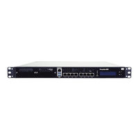
1U Network Appliance with 8th Gen. Intel Core i3, Pentium, Celeron and Intel Xeon E Processor, DDR4, Eight GbE Ports, Two PCIe Slots, M.2, PCIe Mini, Redundant PSU, Rack Mount, and RoHS Compliant
Brand:
IEI Technology
| Category:
Network Hardware
| Size: 4 MB
Table of Contents
Table of Contents
5
1 Introduction
11
Figure 1-1: PUZZLE-IN001 Series
12
Table 1-1: PUZZLE-IN001 Model Variations
13
Front Panel
14
Rear Panel
14
Overview
12
Features
13
Model Variations
13
Figure 1-3: PUZZLE-IN001 Rear Panel
14
Table 1-2: Technical Specifications
16
Dimensions
17
Expansion Slot Block Diagram
17
Figure 1-2: PUZZLE-IN001 Front Panel
14
Technical Specifications
15
Figure 1-4: Expansion Slot Block Diagram
17
Figure 1-5: Physical Dimensions (Millimeters)
18
2 Unpacking
19
Anti-Static Precautions
20
Unpacking Precautions
20
Packing List
21
Optional Items
22
3 Installation
23
Installation Precautions
24
Figure 3-1: Top Cover Removal
25
Figure 3-2: DIMM Slot Locations
26
CPU Installation (PUZZLE-IN001-R Only)
27
Top Cover Removal
25
DIMM Installation
26
Figure 3-3: Disengage the CPU Socket Load Lever
27
Figure 3-4: Remove Protective Cover
28
Figure 3-7: CPU Heatsink Installation
31
Figure 3-8: HDD Bracket Retention Screws
32
Figure 3-9: Secure HDD to the Bracket
32
Pcie Expansion Card Installation
33
Figure 3-6: Close the Socket LGA1155
29
Figure 3-5: Insert the Socket LGA1155 CPU
29
CPU Heatsink Installation (PUZZLE-IN001-R Only)
30
Hdd Installation
31
Figure 3-10: HDD Installation
33
Figure 3-11: Expansion Slot Module Retention Screws
34
Figure 3-12: Disconnect the Expansion Slot Module
34
Figure 3-14: Pcie Expansion Card Installation
35
Figure 3-13: Blank Bracket Screw
35
Figure 3-17: Networking Module Installation
37
Figure 3-16: Networking Module Slot Cover Screws
37
Bypass Configuration in BIOS
38
Module Installation
39
Pcie Mini Card Installation
40
Figure 3-18: Pcie Mini Slot Location
41
Half-Size Pcie Mini Card Installation
41
Figure 3-19: RJ-45 Ethernet Connector
42
Lan Connection
42
Table 3-1: LAN Pinouts
42
Table 3-2: RJ-45 Ethernet Connector Leds
42
Table 3-3: RJ-45 Serial Port Pinouts
43
Figure 3-20: Rack Mount Bracket Installation
46
Rack Mount
46
Figure 3-21: Power-On
47
Power-On Procedure
47
Available Drivers
48
Figure 3-22: IEI Resource Download Center
48
Driver Download
49
Maintenance
50
Power Supply Unit Replacement
51
Clear CMOS
52
Jumper Settings
52
Flash Descriptor Security Override Jumper
53
Console Connection
43
Enable Console Port When Booting
43
Figure 3-15: Expansion Slot Module Installation
36
Iei Networking Module Installation
37
Table 3-4: Flash Descriptor Security Override Jumper Settings
53
Figure 3-23: Clear CMOS Button Location
53
Figure 3-24: Flash Descriptor Security Override Jumper Location
54
4 Bios
55
Introduction
56
Starting Setup
56
Using Setup
56
Getting Help
57
Unable to Reboot after Configuration Changes
57
BIOS Menu Bar
57
Table 4-1: BIOS Navigation Keys
57
Main
58
Advanced
59
CPU Configuration
60
Trusted Computing
61
Iwdd H/W Monitor
62
Smart Fan Mode Configuration
63
IT8528 Super IO Configuration
65
Serial Port 1 Configuration
65
Serial Port Console Redirection
66
Legacy Console Redirection Settings
68
Nvme Configuration
69
Chipset
70
System Agent (SA) Configuration
71
Graphics Configuration
72
Memory Configuration
72
PEG Port Configuration
74
PCH-IO Configuration
75
PCI Express Configuration
76
SATA and RST Configuration
78
Network Configuration (Bypass Setting)
80
Security
81
Boot
82
Save & Exit
84
5 Interface Connectors
85
Peripheral Interface Connectors
86
Internal Peripheral Connectors
87
Table 5-1: Peripheral Interface Connectors
87
ATX Power Connector (ATX1)
88
ATX PSU Smbus Connector (CN3)
88
CPU Power Connector (CPU12V1)
88
Table 5-3: ATX PSU Smbus Connector (CN3) Pinouts
88
Table 5-2: ATX Power Connector Pinouts
88
Chassis Intrusion Connector (CHASSIS1)
89
DIO Connector (DIO1)
89
EC Debug Connector (CN1)
89
Table 5-4: CPU Power Connector (CPU12V1) Pinouts
89
Table 5-7: EC Debug Connector (CN1) Pinouts
90
Table 5-8: Fan Connectors (CPU_FAN1/2/3/4) Pinouts
90
Table 5-9: LCM Connector (CN2) Pinouts
90
Table 5-10: LAN LED Connector (LED_LAN1/2/3/4/5/6/7/8) Pinouts
91
Pcie Mini Card Slot (MPCIE1)
92
Table 5-11: M.2 Slot (M2_1) Pinouts
92
Power Button Connector (PWR_BTN2)
93
SATA Connector (PCIEX1_SLOT1)
93
Table 5-12: Pcie Mini Card Slot (MPCIE1) Pinouts
93
Table 5-13: Power Button Connector (PWR_BTN2) Pinouts
93
SPI Flash Connector (JSPI1)
94
SPI Flash Connector - EC (JSPI2)
94
Table 5-14: SATA 6Gb/S Connector (PCIEX1_SLOT1) Pinouts
94
Table 5-15: SPI Flash Connector (JSPI1) Pinouts
94
Table 5-16: SPI Flash Connector - EC (JSPI2) Pinouts
94
Table 5-17: TPM Connector (TPM1) Pinouts
95
Table 5-18: USB 2.0 Connector (USB1) Pinouts
95
TPM Connector (TPM1)
95
USB 2.0 Connector (USB1)
95
IEI Networking Module Slot a
96
Table 5-19: IEI Networking Module Slot a Pinouts
97
IEI Networking Module Slot B
98
Table 5-5: Chassis Intrusion Connector (CHASSIS1) Pinouts
89
Table 5-6: DIO Connector (DIO1) Pinouts
89
Slot (M2_1)
91
Fan Connectors (CPU_FAN1/2/3/4)
90
LAN LED Connector (LED_LAN1/2/3/4/5/6/7/8)
90
LCM Connector (CN2)
90
Table 5-20: IEI Networking Module Slot B Pinouts
99
Table 5-21: Pcie Link Configuration
99
A Regulatory Compliance
100
B Safety Precautions
105
Safety Precautions
106
General Safety Precautions
106
Anti-Static Precautions
106
Product Disposal
107
Maintenance and Cleaning Precautions
108
Maintenance and Cleaning
108
Cleaning Tools
108
C Error Beep Code
110
Pei Beep Codes
111
Dxe Beep Codes
111
D Hazardous Materials Disclosure
112
Rohs II Directive (2015/863/EU)
113
China Rohs
114
Advertisement
Advertisement
Related Products
IEI Technology PUZZLE-IN001
IEI Technology PUZZLE-IN003B
IEI Technology PUZZLE-IN002
IEI Technology PUZZLE-IN001-R
IEI Technology PUZZLE-IN001-i3T/R
IEI Technology PUZZLE-IN001-i3T/16G/R
IEI Technology PUZZLE-IN001-XE/R
IEI Technology PUZZLE-IN001A
IEI Technology PUZZLE-IN005
IEI Technology PUZZLE-M902
IEI Technology Categories
Motherboard
Touch Panel
Computer Hardware
Single board computers
Desktop
More IEI Technology Manuals
Login
Sign In
OR
Sign in with Facebook
Sign in with Google
Upload manual
Upload from disk
Upload from URL