Table of Contents
Advertisement
Quick Links
Advertisement
Table of Contents

Related Manuals for IEI Technology PUZZLE-IN005


Summary of Contents for IEI Technology PUZZLE-IN005
- Page 1 PUZZLE-IN005 MODEL: PUZZLE-IN005 2U Network Appliance with LGA-4189 Intel® Xeon® Scalable Processor, DDR4 up to 1280GB, PCIe 4.0 x8, GbE with NCSI, IEI Networking Module Slots, M.2, U.2 SSD, Console, Redundant PSU, Rack Mount, and RoHS Compliant User Manual Page 1...
- Page 2 PUZZLE-IN005 Revision Date Version Changes January 13, 2021 1.00 Initial release Page 2...
- Page 3 PUZZLE-IN005 Copyright COPYRIGHT NOTICE The information in this document is subject to change without prior notice in order to improve reliability, design and function and does not represent a commitment on the part of the manufacturer. In no event will the manufacturer be liable for direct, indirect, special, incidental, or consequential damages arising out of the use or inability to use the product or documentation, even if advised of the possibility of such damages.
- Page 4 PUZZLE-IN005 Manual Conventions WARNING Warnings appear where overlooked details may cause damage to the equipment or result in personal injury. Warnings should be taken seriously. CAUTION Cautionary messages should be heeded to help reduce the chance of losing data or damaging the product.
-
Page 5: Table Of Contents
PUZZLE-IN005 Table of Contents 1 INTRODUCTION ......................11 1.1 O ........................ 12 VERVIEW 1.2 F ......................... 12 EATURES 1.3 F ......................13 RONT ANEL 1.4 R ......................14 ANEL 1.5 T ..................14 ECHNICAL PECIFICATIONS 1.6 D ......................16 IMENSIONS 2 UNPACKING ....................... - Page 6 PUZZLE-IN005 3.13.2 Using the IEI iMAN Web GUI ................ 40 3.14 M ....................... 42 AINTENANCE 3.14.1 Power Supply Unit Replacement ..............43 3.14.2 Jumper Settings ....................44 3.14.2.1 Clear CMOS .................... 44 3.14.2.2 Flash Descriptor Security Override Jumper ..........45 4 BIOS ..........................
- Page 7 PUZZLE-IN005 4.5.2.2 Intel® VMD Technology ................72 4.6 S .................... 73 ERVER ANAGEMENT 4.6.1 System Event Log ..................... 74 4.6.2 BMC Network Configuration ................75 4.7 S ......................... 77 ECURITY 4.8 B ........................78 4.9 S & E ......................80 5 INTERFACE CONNECTORS ...................
- Page 8 PUZZLE-IN005 B.1.1 General Safety Precautions ................98 B.1.2 Anti-static Precautions ..................99 B.1.3 Product Disposal ................... 100 B.2 M ............101 AINTENANCE AND LEANING RECAUTIONS B.2.1 Maintenance and Cleaning ................101 B.2.2 Cleaning Tools ....................101 C ERROR BEEP CODE ....................102 C.1 PEI B...
- Page 9 PUZZLE-IN005 List of Figures Figure 1-1: PUZZLE-IN005 Series ....................12 Figure 1-2: PUZZLE-IN005 Front Panel ..................13 Figure 1-3: PUZZLE-IN005 Rear Panel ..................14 Figure 1-4: Physical Dimensions (millimeters) ................16 Figure 3-1: Top Cover Retention Screws ................... 23 Figure 3-2: Top Cover Removal ....................23 Figure 3-3: DIMM Slot Locations ....................
- Page 10 PUZZLE-IN005 List of Tables Table 1-1: Technical Specifications .................... 15 Table 3-1: LAN Pinouts ........................ 30 Table 3-2: RJ-45 Ethernet Connector LEDs ................31 Table 3-3: RJ-45 Serial Port Pinouts ................... 31 Table 3-4: Flash Descriptor Security Override Jumper Settings ..........45 Table 4-1: BIOS Navigation Keys ....................
-
Page 11: Introduction
PUZZLE-IN005 Chapter Introduction Page 11... -
Page 12: Overview
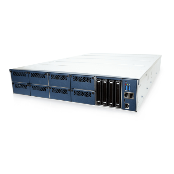
PUZZLE-IN005 1.1 Overview Figure 1-1: PUZZLE-IN005 Series The PUZZLE-IN005 is a 2U network appliance series powered by the LGA-4189 Intel® Xeon® Scalable processors (codenamed Ice Lake). It supports up to 1280 GB DDR4 ECC RDIMM/LRDIMM via 20 memory slots. The PUZZLE-IN005 supports two copper 1GbE ports for high-speed network applications, and it is equipped with eight front-facing PCIe slots for upgrading with IEI networking modules. -
Page 13: Front Panel
CE, FCC and RoHS compliant 1.3 Front Panel The overview of the front panel is shown in Figure 1-2. Figure 1-2: PUZZLE-IN005 Front Panel The states of the LED indicators located on the front panel are listed below. The system is turned off. -
Page 14: Rear Panel
PUZZLE-IN005 1.4 Rear Panel An overview of the PUZZLE-IN005 rear panel is shown in Figure 1-3 below. Figure 1-3: PUZZLE-IN005 Rear Panel 1.5 Technical Specifications The PUZZLE-IN005 technical specifications are listed in Table 1-1. System Form Factor ® ® Processor... -
Page 15: Table 1-1: Technical Specifications
PUZZLE-IN005 Expansion PCIe 1 x PCIe 4.0 x8 slot (HHHL, single width) 2 x M.2 M-key 2280 slot (supporting PCIe 3.0 x4 NVMe) I/O and Indicators Console 1 x RJ-45 1 x USB Type C 2 x USB 3.2 Gen 1 (5Gb/s) port (external) 1 x USB 2.0 internal pin-header (8-pin, p=2.54) -
Page 16: Dimensions
PUZZLE-IN005 1.6 Dimensions The physical dimensions are shown below: Figure 1-4: Physical Dimensions (millimeters) Page 16... -
Page 17: Unpacking
PUZZLE-IN005 Chapter Unpacking Page 17... -
Page 18: Anti-Static Precautions
Follow the anti-static precautions outlined in Section 2.1. Make sure the packing box is facing upwards so the PUZZLE-IN005 does not fall out of the box. Make sure all the components shown in Section 2.3 are present. -
Page 19: Packing List
If some of the components listed in the checklist below are missing, please do not proceed with the installation. Contact the IEI reseller or vendor you purchased the PUZZLE-IN005 from or contact an IEI sales representative directly. To contact an IEI sales representative, please send an email to sales@ieiworld.com. -
Page 20: Optional Items
PUZZLE-IN005 Quantity Item Image Screws (#6-32*6) for handle installation USB to console cable 2.4 Optional Items The following table lists the optional items that can be purchased separately. Optional Item Image Sliding rails for rack mount (P/N: RAIL-A03-57) USB to console cable (P/N: 32013-004000-100-RS) 20-pin Infineon TPM 2.0 module, software... -
Page 21: Installation
PUZZLE-IN005 Chapter Installation Page 21... -
Page 22: Installation Precautions
PUZZLE-IN005 3.1 Installation Precautions CAUTION! The PUZZLE-IN005 series has more than one power supply connection point. To reduce the risk of electric shock, disconnect all power sources before installing or servicing the PUZZLE-IN005 series. During installation, be aware of the precautions below: ... -
Page 23: Top Cover Removal
Before installing or maintaining the internal components, the top cover must be removed from the PUZZLE-IN005. Follow the steps below to complete the task. Step 1: Remove the four retention screws on the top panel (see Figure 3-1). -
Page 24: Dimm Installation
To install the DIMM module, please follow the steps below. Step 1: Remove the top cover from the PUZZLE-IN005. Please follow the instruction described in Section 3.2. Step 2: Locate the DIMM slots on the motherboard. -
Page 25: Pcie Expansion Card Installation
0: 3.4 PCIe Expansion Card Installation The PUZZLE-IN005 allows installation of one PCIe x8 card. To install a PCIe expansion card, please follow the steps below. Step 1: Remove the top cover from the PUZZLE-IN005 (refer to Section 3.2). -
Page 26: Module Installation
The M.2 slots are keyed in the M position and provide mounting screw position for 2280-size M.2 modules. To install an M.2 module, please follow the steps below. Step 1: Remove the top cover from the PUZZLE-IN005. See Section 3.2. Step 2: Locate the M.2 slot on the motherboard. -
Page 27: Ssd Installation
PUZZLE-IN005 3.6 SSD Installation Four 2.5" U.2 SSD can be installed in the PUZZLE-IN005. The SSDs are installed into the removable hard drive trays on the front panel. To install the SSD into the system, please follow the steps below. -
Page 28: Figure 3-7: Ssd Retention Screws
PUZZLE-IN005 Step 3: Place an SSD onto the drive tray and secure the SSD with the bracket by inserting four retention screws (M3*4) into the bottom of the SSD (Figure 3-7). Figure 3-7: SSD Retention Screws Step 4: Carefully insert the SSD into the slot on the front panel. Make sure the SATA connector on the SSD is securely connected to the SATA connector inside the chassis. -
Page 29: Iei Networking Module Installation
PUZZLE-IN005 3.7 IEI Networking Module Installation The PUZZLE-IN005 allows installation of eight IEI PulM networking modules. To install a networking module, please follow the steps below. Step 1: Disconnect all power sources from the system. NOTE: To install or replace the networking module, the power supply must be fully disconnected before installation. -
Page 30: Lan Connection
PUZZLE-IN005 CAUTION: When inserting the module, the bottom of the networking module must be as close to the slot base as possible so that the module can be slid into the guide rails. When removing the module, slide the module horizontally all the way until it is completely out of the system. -
Page 31: Console Connection
Table 3-2: RJ-45 Ethernet Connector LEDs 3.9 RJ-45 Console Connection The PUZZLE-IN005 has one RJ-45 serial device connector on the front panel. The RJ-45 connector for the serial port can be identified easily as the RJ-45 for the network has two LEDs on the port, while the connectors for the serial cables don’t. -
Page 32: Enable Console Port When Booting
PUZZLE-IN005 3.9.1 Enable Console Port When Booting To configure the PUZZLE-IN005 to make it auto enable the console port when booting, follow the steps below. NOTE: This method only works in Linux Ubuntu, the default operating system. Step 1: Use the console cable shipped with the product to connect the RJ-45 console port of the PUZZLE-IN005 with your PC. - Page 33 PUZZLE-IN005 Step 6: Enter the following command: sudo vi /lib/systemd/system/ttyS0.service Step 7: Ensure the information shown match the followings: [Unit] Description=Serial Console Service [Service] ExecStart=/sbin/getty -L 115200 ttyS0 vt102 Restart=always [Install] WantedBy=multi-user.target Step 8: Run the following commands one by one:...
-
Page 34: Rack Mount
PUZZLE-IN005 3.10 Rack Mount The PUZZLE-IN005 is shipped with two rack mount brackets that could be used to secure the system to the rack after mounting it with the optional sliding rails. To install the PUZZLE-IN005 into a rack, please follow the steps below. -
Page 35: Figure 3-13: Handle Installation
Install the sliding rails according to the instruction came with the sliding rails. Note: The sliding rails must be purchased separately. Step 4: Slide the PUZZLE-IN005 all the way into the rack enclosure. Step 5: Secure the front of the rack mount brackets that are attached to the sides of the PUZZLE-IN005 to the front of the rack. -
Page 36: Power-On Procedure
2. Ensure to connect the power cord to a socket-outlet with earthing connection. To power-on the PUZZLE-IN005 please follow the steps below: Step 1: Connect the power source to the power inlets on the rear panel. -
Page 37: Available Drivers
PUZZLE-IN005 3.12 Available Drivers All the drivers for the PUZZLE-IN005 are available on IEI Resource Download Center (https://download.ieiworld.com). Type PUZZLE-IN005 and press Enter to find all the relevant software, utilities, and documentation. Figure 3-15: IEI Resource Download Center NOTE: To install software from the downloaded ISO image file in Windows 10, double-click the ISO file to mount it as a virtual drive to view its content. -
Page 38: Driver Download
3.12.1 Driver Download To download drivers from IEI Resource Download Center, follow the steps below. Step 1: Go to https://download.ieiworld.com. Type PUZZLE-IN005 and press Enter. Step 2: All product-related software, utilities, and documentation will be listed. You can choose Driver to filter the result. -
Page 39: Ipmi Setup Procedure
The PUZZLE-IN005 features Intelligent Platform Management Interface (IPMI) that helps lower the overall costs of server management by enabling users to maximize IT resources, save time and manage multiple systems. The PUZZLE-IN005 supports IPMI 2.0 through the pre-installed iRIS-2400 module. Follow the steps below to setup IPMI. -
Page 40: Using The Iei Iman Web Gui
IP address, follow the steps below: a. Copy the Ipmitool.exe file to a bootable USB flash drive. b. Insert the USB flash drive to the PUZZLE-IN005 c. The PUZZLE-IN005 boots from the USB flash drive d. Enter the following command: ipmitool 20 30 02 01 03 00 00 (there is a space between each two-digit number) e. -
Page 41: Figure 3-17: Iei Iman Web Gui
PUZZLE-IN005 Figure 3-17: IEI iMAN Web GUI NOTE: To understand how to use the IEI iMAN Web GUI, please refer to the iRIS-2400 Web GUI user manual which can be downloaded from https://download.ieiworld.com/. The user manual describes each function in detail. -
Page 42: Maintenance
The following instructions should only be performed by an authorized and trained technician. Before starting, please ensure that you turn off the PUZZLE-IN005, disconnect the power cords, network cable(s), and also remove any other device/cable that is attached to the server. -
Page 43: Power Supply Unit Replacement
3.14.1 Power Supply Unit Replacement To replace a failed power supply unit, please follow the steps below. Step 1: Turn off the PUZZLE-IN005. Disconnect the power cords, network cable(s), and any other connectors or cables from the PUZZLE-IN005. Step 2: Firmly press and hold the blue button on back of PSU inwards. -
Page 44: Jumper Settings
Step 0: 3.14.2.1 Clear CMOS If the PUZZLE-IN005 fails to boot due to improper BIOS settings, the clear CMOS button clears the CMOS data and resets the system BIOS information. To do this, push the clear CMOS button for a few seconds. -
Page 45: Flash Descriptor Security Override Jumper
PUZZLE-IN005 Figure 3-18: Clear CMOS Button Location 3.14.2.2 Flash Descriptor Security Override Jumper The Flash Descriptor Security Override jumper (J_FLASH1) allows users to enable or disable the ME firmware update. Refer to Figure 3-19 and Table 3-4 for the jumper location and settings. - Page 46 PUZZLE-IN005 To update the ME firmware, please follow the steps below. Step 1: Before turning on the system power, short pin 2-3 of the jumper. Step 2: Update the BIOS and ME firmware, and then turn off the system power.
-
Page 47: Bios
PUZZLE-IN005 Chapter BIOS Page 47... -
Page 48: Introduction
PUZZLE-IN005 4.1 Introduction The BIOS is programmed onto the BIOS chip. The BIOS setup program allows changes to certain system settings. This chapter outlines the options that can be changed. NOTE: Some of the BIOS options may vary throughout the life cycle of the product and are subject to change without prior notice. -
Page 49: Getting Help
PUZZLE-IN005 Function Decrease the numeric value or make changes Esc key Main Menu – Quit and not save changes into CMOS Status Page Setup Menu and Option Page Setup Menu -- Exit current page and return to Main Menu F1 key... -
Page 50: Main
PUZZLE-IN005 The following sections completely describe the configuration options found in the menu items at the top of the BIOS screen and listed above. 4.2 Main The Main BIOS menu (BIOS Menu 1) appears when the BIOS Setup program is entered. -
Page 51: Advanced
PUZZLE-IN005 System Time [xx:xx:xx] Use the System Time option to set the system time. Manually enter the hours, minutes and seconds. 4.3 Advanced Use the Advanced menu (BIOS Menu 2) to configure the peripheral devices through the following sub-menus:... -
Page 52: Trusted Computing
PUZZLE-IN005 Restore AC Power Loss [Last State] Use the Restore AC Power Loss BIOS option to specify what state the system returns to if there is a sudden loss of power to the system. Power Off The system remains turned off ... -
Page 53: Iwdd H/W Monitor
PUZZLE-IN005 Security Device Support [Disable] Use the Security Device Support option to configure support for the TPM. TPM support is disabled. Disable EFAULT TPM support is enabled. Enable 4.3.2 iWDD H/W Monitor The iWDD H/W Monitor menu (BIOS Menu 4) contains the fan configuration submenu, and displays the system temperature and CPU fan speed. - Page 54 PUZZLE-IN005 PC Health Status The following system parameters and values are shown. The system parameters that are monitored are: System Temperatures: CPU Temperature System Temperature Environment Temperature Fan Speeds: CPU Fan Speed System Fan Speed Voltages:...
-
Page 55: Smart Fan Mode Configuration
PUZZLE-IN005 4.3.2.1 Smart Fan Mode Configuration Use the Smart Fan Mode Configuration submenu (BIOS Menu 5) to configure the CPU/system fan temperature and speed settings. Aptio Setup – American Megatrends International, LLC. Advanced Smart Fan Mode Configuration Smart Fan Mode Select... -
Page 56: It8528 Super Io Configuration
PUZZLE-IN005 Auto mode fan off temperature If the CPU temperature is lower than the value set this option, the fan speed change to be lowest. To set a value, Use the + or – key to change the value or enter a decimal number between 1 and 100. -
Page 57: Serial Port 1 Configuration
PUZZLE-IN005 4.3.3.1 Serial Port 1 Configuration Use the Serial Port 1 Configuration menu (BIOS Menu 7) to configure the serial port 1. Aptio Setup – American Megatrends International, LLC. Advanced Serial Port 1 Configuration Enable or Disable Serial Port (COM) - Page 58 PUZZLE-IN005 Aptio Setup – American Megatrends International, LLC. Advanced Console Redirection COM1 Console Redirection [Enabled] Enable or Disable > Console Redirection Settings Legacy Console Redirection -------------------- : Select Screen > Legacy Console Redirection Settings ↑ ↓: Select Item Enter: Select +/-: Change Opt.
- Page 59 PUZZLE-IN005 Bits per second [115200] Use the Bits per second option to specify the serial port transmission speed. The speed must match the other side. Long or noisy lines may require lower speeds. 9600 Sets the serial port transmission speed at 9600.
-
Page 60: Legacy Console Redirection Settings
PUZZLE-IN005 Stop Bits [1] Use the Stop Bits option to specify the number of stop bits used to indicate the end of a serial data packet. Communication with slow devices may require more than 1 stop bit. Sets the number of stop bits at 1. -
Page 61: Nvme Configuration
PUZZLE-IN005 4.3.5 NVMe Configuration Use the NVMe Configuration (BIOS Menu 10) menu to display the NVMe controller and device information. Aptio Setup – American Megatrends International, LLC. Advanced NVMe Configuration No NVME Device Found --------------------- : Select Screen ↑ ↓: Select Item Enter: Select +/-: Change Opt. -
Page 62: Platform Configuration
PUZZLE-IN005 4.4 Platform Configuration Use the Platform Configuration menu (BIOS Menu 11) to configure the platform parameters. Aptio Setup – American Megatrends International, LLC. Main Advanced Platform Configuration Socket Configuration Server Mgmt > > PCH Configuration Displays and provides option to change the PCH... -
Page 63: Pci Express Configuration
PUZZLE-IN005 4.4.1.1 PCI Express Configuration Use the PCI Express Configuration menu (BIOS Menu 13) to configure the PCI Express slot. Aptio Setup – American Megatrends International, LLC. Platform Configuration > M2_M2 M2_M2 Settings. > M2_M1 ---------------------- : Select Screen ↑ ↓: Select Item Enter: Select +/-: Change Opt. -
Page 64: Pch Sata Configuration
PUZZLE-IN005 PCIe Speed [Auto] Use this option to select the support type of the PCI Express slots. The following options are available: Auto Default Gen1 Gen2 Gen3 4.4.1.2 PCH SATA Configuration Use the PCH SATA Configuration menu (BIOS Menu 15) to change and/or set the configuration of the SATA devices installed in the system. -
Page 65: Pch Ssata Configuration
PUZZLE-IN005 Configure SATA as [AHCI] Use the Configure SATA as option to determine how the SATA devices operate. AHCI Configures SATA devices as AHCI device. EFAULT RAID Configures SATA devices as RAID device. Hot Plug [Enable] Use the Hot Plug option to enable or disable the hot plug function. - Page 66 PUZZLE-IN005 SATA Controller [Enable] Use the SATA Controller option to enable or disable the SATA device. Enables the SATA device. Enable EFAULT Disables the SATA device. Disable Configure sSATA as [AHCI] Use the Configure sSATA as option to configure how the SATA controller(s) operate.
-
Page 67: Socket Configuration
PUZZLE-IN005 4.5 Socket Configuration Use the Socket Configuration menu (BIOS Menu 17) to configure the socket parameters. Aptio Setup – American Megatrends International, LLC. Main Advanced Platform Configuration Socket Configuration Server Mgmt > > Processor Configuration Displays and provides > IIO Configuration... -
Page 68: Processor Configuration
PUZZLE-IN005 4.5.1 Processor Configuration Use the Processor Configuration menu (BIOS Menu 18) to view detailed CPU specifications or enable the Intel Virtualization Technology. Aptio Setup – American Megatrends International, LLC. Socket Configuration Processor Configuration Enable Hyper Threading -------------------------------------------------- (Software Method to Processor BSP Revision 606A4 –... -
Page 69: Iio Configuration
PUZZLE-IN005 VMX [Enable] Use the VMX option to enable or disable virtualization on the system. When combined ® with third party software, Intel Virtualization technology allows several OSs to run on the same system at the same time. ... -
Page 70: Socket0 Configuration
PUZZLE-IN005 4.5.2.1 Socket0 Configuration Use the Socket0 Configuration menu (BIOS Menu 20) to view the PCIe socket 0 information. Aptio Setup – American Megatrends International, LLC. Socket Configuration IOU0 (IIO PCIe Port 1) [Auto] IOU1 (IIO PCIe Port 2) [x16]... -
Page 71: Intel® Vt For Directed I/O (Vt-D)
PUZZLE-IN005 4.5.2.1 Intel® VT for Directed I/O (VT-d) Use the Intel® VT for Directed I/O (VT-d) submenu (BIOS Menu 22) to disable or enable Intel® Virtualization Technology for directed I/O (VT-d). Aptio Setup – American Megatrends International, LLC. Socket Configuration Intel®... -
Page 72: Intel® Vmd Technology
PUZZLE-IN005 4.5.2.2 Intel® VMD Technology Use the Intel® VMD Technology submenu (BIOS Menu 23) to configure Intel® VMD (Volume Management Device) settings. Aptio Setup – American Megatrends International, LLC. Socket Configuration Intel® VMD technology --------------------------------------------------- Intel® VMD for Volume Management Device on ... -
Page 73: Server Management
PUZZLE-IN005 4.6 Server Management Use the Server Management menu (BIOS Menu 24) to display the server management status and change the settings. Aptio Setup – American Megatrends International, LLC. Main Advanced Platform Configuration Socket Configuration Server Mgmt > BMC Self Test Status FAILED Press <Enter>... -
Page 74: System Event Log
PUZZLE-IN005 4.6.1 System Event Log Use the System Event Log menu (BIOS Menu 25) to configure the System Event Log (SEL) options. Aptio Setup – American Megatrends International, LLC. Server Mgmt Enabling/Disabling Options Change this to enable or SEL Components... -
Page 75: Bmc Network Configuration
PUZZLE-IN005 When SEL is full [Do Nothing] Use the When SEL is Full option to determine the action to be taken when SEL is full. The following options are available: Do Nothing Default Erase Immediately Delete Oldest Record 4.6.2 BMC Network Configuration... - Page 76 PUZZLE-IN005 Configuration Address Source [Unspecified] Use the Configuration Address Source option to select the BMC network address source. Does not modify any BMC network Unspecified EFAULT parameters during BIOS phase Manually sets network Static parameters. If this option is selected, the following...
-
Page 77: Security
PUZZLE-IN005 4.7 Security Use the Security menu (BIOS Menu 27) to set system and user passwords. Aptio Setup – American Megatrends International, LLC. < Security Boot Save & Exit Password Description Set Administrator Password If ONLY the Administrator’s password is set, then this only limits access to Setup and is only asked for when entering Setup. -
Page 78: Boot
PUZZLE-IN005 4.8 Boot Use the Boot menu (BIOS Menu 28) to configure system boot options. Aptio Setup – American Megatrends International, LLC. < Security Boot Save & Exit Boot Configuration Select the keyboard Bootup NumLock State [On] NumLock state Quiet Boot... - Page 79 PUZZLE-IN005 Quiet Boot [Enabled] Use the Quiet Boot BIOS option to select the screen display when the system boots. Normal POST messages displayed Disabled OEM Logo displayed instead of POST messages Enabled EFAULT UEFI Boot [Disabled] Use the UEFI Boot option to enable or disable to boot from the UEFI devices.
-
Page 80: Save & Exit
PUZZLE-IN005 4.9 Save & Exit Use the Safe & Exit menu (BIOS Menu 29) to load default BIOS values, optimal failsafe values and to save configuration changes. Aptio Setup – American Megatrends International, LLC. < Security Boot Save & Exit... -
Page 81: Interface Connectors
PUZZLE-IN005 Chapter Interface Connectors Page 81... -
Page 82: Peripheral Interface Connectors
PUZZLE-IN005 5.1 Peripheral Interface Connectors The connector locations of the PUZZLE-IN005’s motherboard are shown below. The connector pinouts for these connectors are listed in the following sections. 5.2 Internal Peripheral Connectors Internal peripheral connectors on the motherboard are only accessible when the motherboard is outside of the chassis. -
Page 83: Chassis Intrusion Connector (Con1)
PUZZLE-IN005 Connector Type Label Debug port connector 12-pin wafer DBG_PORT1 EC debug connector 20-pin FPC CON2 Fan connectors, CPU 4-pin wafer CPU_FAN1, CPU_FAN2 Fan connectors, system 4-pin wafer SYS_FAN1, SYS_FAN2, SYS_FAN3, SYS_FAN4, SYS_FAN5 LCM connector 8-pin wafer LCM1 M.2 M-key slot M.2 M-key 2280... -
Page 84: Cpld Programmer Connector (J1)
PUZZLE-IN005 5.2.2 CPLD Programmer Connector (J1) PIN NO. DESCRIPTION +3.3V_SB CPLD_TDO CPLD_TDI CPLD_TMS CPLD_TCK Table 5-3: CPLD Programmer Connector (J1) Pinouts 5.2.3 Debug Port Connector (DBG_PORT1) Description Description SERIRQ LAD3 LAD2 LAD1 LAD0 FRAME# RESET# CLOCK Table 5-4: Debug Port Connector (DBG_PORT1) Pinouts... -
Page 85: Ec Debug Connector (Con2)
PUZZLE-IN005 5.2.4 EC Debug Connector (CON2) PIN NO. DESCRIPTION PIN NO. DESCRIPTION KSI0 KSO0 KSO1 KSO2 KSO3 KSO4 KSO5 KSO6 KSO7 KSO8 KSO9 KSO10 KS12 KSI1 KSO11 KSI2 KSI3 Table 5-5: EC Debug Connector (CON2) Pinouts 5.2.5 CPU Fan Connectors (CPU_FAN1/2) PIN NO. -
Page 86: Lcm Connector (Lcm1)
PUZZLE-IN005 5.2.7 LCM Connector (LCM1) PIN NO. DESCRIPTION VCC5V Power button LCM RX LCM TX HDD LED Alert LED Reset button Table 5-8: LCM Connector (LCM1) Pinouts 5.2.8 M.2 M-key Slot (M2_M1/M2_M2) PIN NO. DESCRIPTION PIN NO. DESCRIPTION +3.3V +3.3V... -
Page 87: Power Button Connector (Pwr_Btn1)
PUZZLE-IN005 PIN NO. DESCRIPTION PIN NO. DESCRIPTION PCIE_TXN1 PCIE_TXP1 DEVSLP PCIE_RXN0 PCIE_RXP0 PCIE_TXN0 PCIE_TXP0 PERST# CLKREQ# REFCLKN PEWAKE REFCLKP Module Key Module Key Module Key Module Key Module Key Module Key Module Key Module Key SUSCLK PEDET +3.3V +3.3V +3.3V Table 5-9: M.2 M-key Slot (M2_M1/M2_M2) Pinouts... -
Page 88: Power Connector, I/O Card (Io_Pwr1)
PUZZLE-IN005 5.2.10 Power Connector, I/O Card (IO_PWR1) PIN NO. DESCRIPTION 3.3V 3.3V Table 5-11: Power Connector, I/O Card (IO_PWR1) Pinouts 5.2.11 Power Connector, Networking Card (HDD_PWR2) PIN NO. DESCRIPTION Table 5-12: Power Connector, Networking Card (HDD_PWR2) Pinouts 5.2.12 Power Connector, Riser Card (RISER_PWR1) PIN NO. -
Page 89: Sata Raid Key Connector (Con11)
PUZZLE-IN005 5.2.13 SATA RAID Key Connector (CON11) PIN NO. DESCRIPTION RAID KEY Table 5-14: SATA RAID Key Connector (CON11) Pinouts 5.2.14 SMBus Connector (SMB1) PIN NO. DESCRIPTION SMBUS (I2C) CLK SMBUS (I2C) DATA Table 5-15: SMBus Connector (SMB1) Pinouts 5.2.15 CPU SMBus Connector (CPU_SMB1) PIN NO. -
Page 90: Spi Flash Connector (Jspi1)
PUZZLE-IN005 5.2.16 SPI Flash Connector (JSPI1) PIN NO. DESCRIPTION +3.3V SPI_CS SPI_SO SPI_CLK SPI_SI Table 5-17: SPI Flash Connector (JSPI1) Pinouts 5.2.17 SPI Flash Connector - EC (JSPI2) PIN NO. DESCRIPTION +3.3V SPI_CS#0_CN_EC SPI_SO_SW_EC SPI_CLK_SW_EC SPI_SI_SW_EC Table 5-18: SPI Flash Connector - EC (JSPI2) Pinouts 5.2.18 TPM Connector (TPM1) -
Page 91: Usb Dom Connector (Usb_Dom1)
PUZZLE-IN005 PIN NO. DESCRIPTION PIN NO. DESCRIPTION SB3V SERIRQ GLKRUN# LPCPD# LDRQ# Table 5-19: TPM Connector (TPM1) Pinouts 5.2.19 USB DOM Connector (USB_DOM1) PIN NO. DESCRIPTION PIN NO. DESCRIPTION USB_DATA- USB_DATA+ Table 5-20: USB DOM Connector (USB_DOM1) Pinouts 5.2.20 VGA Connector (VGA1) PIN NO. -
Page 92: A Regulatory Compliance
PUZZLE-IN005 Appendix Regulatory Compliance Page 92... - Page 93 PUZZLE-IN005 DECLARATION OF CONFORMITY This equipment is in conformity with the following EU directives: EMC Directive 2014/30/EU Low-Voltage Directive 2014/35/EU RoHS II Directive 2011/65/EU If the user modifies and/or install other devices in the equipment, the CE conformity declaration may no longer apply.
- Page 94 PUZZLE-IN005 Español [Spanish] IEI Integration Corp declara que el equipo cumple con los requisitos esenciales y cualesquiera otras disposiciones aplicables o exigibles de la Directiva 1999/5/CE. Ελληνική [Greek] IEI Integration Corp ΔΗΛΩΝΕΙ ΟΤΙ ΕΞΟΠΛΙΣΜΟΣ ΣΥΜΜΟΡΦΩΝΕΤΑΙ ΠΡΟΣ ΤΙΣ ΟΥΣΙΩΔΕΙΣ ΑΠΑΙΤΗΣΕΙΣ ΚΑΙ ΤΙΣ ΛΟΙΠΕΣ ΣΧΕΤΙΚΕΣ ΔΙΑΤΑΞΕΙΣ ΤΗΣ ΟΔΗΓΙΑΣ...
- Page 95 PUZZLE-IN005 Româna [Romanian] IEI Integration Corp declară că acest echipament este in conformitate cu cerinţele esenţiale şi cu celelalte prevederi relevante ale Directivei 1999/5/CE. Slovensko [Slovenian] IEI Integration Corp izjavlja, da je ta opreme v skladu z bistvenimi zahtevami in ostalimi relevantnimi določili direktive 1999/5/ES.
- Page 96 PUZZLE-IN005 FCC WARNING This equipment complies with Part 15 of the FCC Rules. Operation is subject to the following two conditions: This device may not cause harmful interference, and This device must accept any interference received, including interference that may cause undesired operation.
-
Page 97: B Safety Precautions
PUZZLE-IN005 Appendix Safety Precautions Page 97... -
Page 98: Safety Precautions
WARNING: The precautions outlined in this appendix should be strictly followed. Failure to follow these precautions may result in permanent damage to the PUZZLE-IN005. Please follow the safety precautions outlined in the sections that follow: B.1.1 General Safety Precautions Please ensure the following safety precautions are adhered to at all times. -
Page 99: Anti-Static Precautions
Electrostatic discharge (ESD) can cause serious damage to electronic components, including the PUZZLE-IN005. Dry climates are especially susceptible to ESD. It is therefore critical that whenever the PUZZLE-IN005 is opened and any of the electrical components are handled, the following anti-static precautions are strictly adhered to. -
Page 100: Product Disposal
PUZZLE-IN005 B.1.3 Product Disposal CAUTION: Risk of explosion if the battery is replaced by an incorrect type; Replacement of a battery with an incorrect type that can defeat a safeguard (for example, in the case of some lithium battery types);... -
Page 101: Maintenance And Cleaning Precautions
B.2 Maintenance and Cleaning Precautions When maintaining or cleaning the PUZZLE-IN005, please follow the guidelines below. B.2.1 Maintenance and Cleaning Prior to cleaning any part or component of the PUZZLE-IN005, please read the details below. The interior of the PUZZLE-IN005 does not require cleaning. Keep fluids away from the PUZZLE-IN005 interior. -
Page 102: C Error Beep Code
PUZZLE-IN005 Appendix Error Beep Code Page 102... -
Page 103: Pei Beep Codes
PUZZLE-IN005 C.1 PEI Beep Codes Number of Beeps Description Memory not Installed Memory was installed twice (InstallPeiMemory routine in PEI Core called twice) Recovery started DXEIPL was not found DXE Core Firmware Volume was not found Recovery failed S3 Resume failed Reset PPI is not available C.2 DXE Beep Codes... -
Page 104: D Hazardous Materials Disclosure
PUZZLE-IN005 Appendix Hazardous Materials Disclosure Page 104... -
Page 105: Rohs Ii Directive (2015/863/Eu)
PUZZLE-IN005 D.1 RoHS II Directive (2015/863/EU) The details provided in this appendix are to ensure that the product is compliant with the RoHS II Directive (2015/863/EU). The table below acknowledges the presences of small quantities of certain substances in the product, and is applicable to RoHS II Directive (2015/863/EU). -
Page 106: China Rohs
PUZZLE-IN005 D.2 China RoHS 此附件旨在确保本产品符合中国 RoHS 标准。以下表格标示此产品中某有毒物质的含量符 合中国 RoHS 标准规定的限量要求。 本产品上会附有”环境友好使用期限”的标签,此期限是估算这些物质”不会有泄漏或突变”的 年限。本产品可能包含有较短的环境友好使用期限的可替换元件,像是电池或灯管,这些 元件将会单独标示出来。 部件名称 有毒有害物质或元素 壳体 显示 印刷电路板 金属螺帽 电缆组装 风扇组装 电力供应组装 电池 O: 表示该有毒有害物质在该部件所有物质材料中的含量均在 SJ/T11364-2014 與 GB/T26572-2011 标准规定的限量要求以下。 X: 表示该有毒有害物质至少在该部件的某一均质材料中的含量超出 SJ/T11364-2014 與 GB/T26572-2011 标准规定的限量要求。 Page 106...
Need help?
Do you have a question about the PUZZLE-IN005 and is the answer not in the manual?
Questions and answers