
Subscribe to Our Youtube Channel
Related Manuals for Badger Meter MN Series


Summary of Contents for Badger Meter MN Series
- Page 1 Model F110 Display /Totalizer Instruction and operation manual AC_F110_BA_02_1346 (November 2014)
- Page 2 Model F110, Display / Totalizer Page II AC_F110_BA_02_1346 November 2014...
-
Page 3: Table Of Contents
User manual CONTENT 1. Safety instructions ........................................... 1 1.1 Basics ..............................................1 1.2 Safety guidelines and measures .................................... 1 2. Repairs ................................................. 1 3. To the owner ............................................. 2 4. Introduction ............................................... 3 4.1 System description of the F110 ..................................... 3 4.2 Control panel .......................................... - Page 4 Model F110, Display / Totalizer 6.4.9 Others – 9 ........................................12 7. Installation ............................................... 13 7.1 Hints .............................................. 13 7.2 Installation / environmental conditions ................................13 7.3 Housing dimensions ....................................... 14 7.4 Hardware installation ......................................14 7.5 Terminal connectors ....................................... 15 7.5.1 Overview ........................................
-
Page 5: Safety Instructions
Safety instructions 1. SAFETY INSTRUCTIONS 1.1 Basics The manufacturer is not liable for damages that result from improper or not in accordance with the requirements use. The meters are constructed according to state-of-the-art technology and tested operationally reliable. They have left the factory in a faultless condition concerning safety regulations. -
Page 6: To The Owner
3. TO THE OWNER Thank you for purchasing a MN series flow meter and accessories. Please take a few minutes to read through this manual before installing and operating your meter. If you have any problems with the meter, refer to the maintenance and troubleshooting sections of this manual. -
Page 7: Introduction
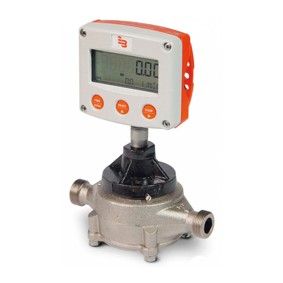
Introduction 4. INTRODUCTION 4.1 System description of the F110 The display / totalizer F110 is a battery-powered device driven by microprocessors for displaying of the flow rate, total and accumulated total. For that purpose, one flow meter can be connected to the F110. Two outputs are standardly available: •... -
Page 8: Operation
Operation 5. OPERATION 5.1 In general This chapter describes the daily use of the display / totalizer. This instruction is meant for the users/operators. In general, the display/totalizer will always act at operator level. The information displayed depends on the SETUP settings. Although the refresh rate of the display might be slow (due to power management functions), each flow meter pulse will be measured. -
Page 9: Configuration / Setup
Configuration / setup 6. CONFIGURATION / SETUP 6.1 In general • Mounting, electrical installation, start-up and maintenance of the instrument may only be carried out by trained personnel authorized by the operator of the facility. Personnel must read and understand this operating manual before carrying out its instructions. -
Page 10: Scrolling Through Setup
Configuration / setup 6.3 Scrolling through SETUP 6.3.1 SELECTION OF FUNCTIONS GROUP AND FUNCTION SETUP level is divided into several function groups and functions. Select a function group with Select a function with Each function has a unique number, which is displayed below the word "SETUP" at the bottom of the display. The number is a combination of two figures. -
Page 11: To Return To The Operator Level
Configuration / setup 6.3.3 TO RETURN TO THE OPERATOR LEVEL Press for 3 seconds 6.3.4 FUNCTIONS OVERVIEW OF THE SETUP LEVEL Decimals K-factor: 0-6 K-factor: 0.000010 - 9,999,999 Decimals: 0 - 1 - 2 -3 Total Unit: L - m - kg - lb - GAL - USGAL - bbl - no unit Cut-off: 0.1 - 999.9 seconds Calculation: per 1 - 99 pulses... -
Page 12: Explanations Of The Setup Functions
Configuration / setup 6.4 Explanations of the SETUP functions 6.4.1 TOTALIZER – 1 Measurement unit - 11: SETUP - 11 determines the measurement unit for total and accumulated total. The following units can be selected: L - m3 - kg - lb - GAL - USGAL - bbl - _ (no unit). Alterations of the measurement unit will have consequences for operator and SETUP level values. -
Page 13: Flow Rate - 2
Configuration / setup 6.4.2 FLOW RATE – 2 The settings for total and flow rate are entirely separated. In this way, different measurement units can be used like cubic meters for total and liters for flow rate. Please notice that all these settings influence the analog output as well. Measurement unit - 21: SETUP - 21 determines the measurement unit for flow rate. -
Page 14: Display - 3
Configuration / setup 6.4.3 DISPLAY - 3 Function - 31 The large 17 mm digits can be set to display total or flow rate digits at operator level. When total is selected, both total and flow rate are displayed simultaneously. When flow rate is selected, total will be displayed after pressing select. 6.4.4 POWER MANAGEMENT - 4 As the F110 is normally battery powered, the user will have the concern of reliable measurement over a long period of time. -
Page 15: Analog Output - 6
Configuration / setup 6.4.6 ANALOG OUTPUT - 6 A passive linear 4-20mA output signal is generated according to the flow rate with a 10 bit resolution. The settings for flow rate (SETUP - 2) influences the analogue output directly. When the analogue output is not used, please make sure that setting 61 is disabled, else the battery lifetime will be decreased significantly! The relationship between rate and analogue output is set with following functions: Enable / disable - 61:... -
Page 16: Communication (Optional) - 8
Configuration / setup 6.4.8 COMMUNICATION (OPTIONAL) - 8 Functions as described below deal with hardware that is not part of the standard delivery. Programming of these functions does not have any effect if this hardware has not been installed. Baud Rate (optional) - 81: For external control, following communication speeds can be selected: 1200 - 2400 - 4800 - 9600 baud Bus address (optional) - 82: For RS485 communication, a unique identity can be attributed to every F110. -
Page 17: Installation
Installation 7. INSTALLATION 7.1 Hints • MOUNTING, ELECTRICAL INSTALLATION, START-UP AND MAINTENANCE OF THIS INSTRUMENT MAY ONLY BE CARRIED OUT BY TRAINED PERSONNEL AUTHORIZED BY THE OPERATOR OF THE FACILITY. PERSONNEL MUST READ AND UNDERSTAND THIS OPERATING MANUAL BEFORE CARRYING OUT ITS INSTRUCTIONS. •... -
Page 18: Housing Dimensions
Installation 7.3 Housing dimensions Standard IP65 (NEMA 4) ABS housing Front view panel cut-out Side view (panel mount) bottom view 7.4 Hardware installation ELECTROSTATIC DISCHARGE DOES INFLICT IRREPARABLE DAMAGE TO ELECTRONICS! BEFORE INSTALLING OR OPENING THE UNIT, THE INSTALLER HAS TO DISCHARGE HIMSELF BY TOUCHING A WELL GROUNDED OBJECT. -
Page 19: Terminal Connectors
Installation 7.5 Terminal connectors 7.5.1 OVERVIEW ext. power- supply Pulse- Analogue output Output 5-30 VAC/DC Sensor signal input For installation, pay special attention to: • SEPARATED CABLE GLANDS WITH EFFECTIVE IP67 SEALS FOR ALL WIRES. • NOT USED CABLE ENTRIES: DO PLACE CLOSED IP67 PLUGS. •... -
Page 20: Pulse Output
Installation 7.5.3 PULSE OUTPUT (connectors 4-5, SETUP 71) An open collector output generates a pulse of 100 msec. (setting long) or 25msec. (setting short) according to a certain quantity. This output can be used for driving an external counter relay e.g. For power-consumption reasons, it is advised to select "OFF"... -
Page 21: Inputs
Installation 7.5.6 INPUTS (connectors 9-12) Two basic types of flow meter signals can be connected to the F110: pulse (terminal 10) or coil (terminal 11). The screen of the signal wire must be connected to terminal 9 (GND). The voltage supply (3.2VDC) to the flow meter should be connected to terminal 12. -
Page 22: Option - Communication / Printer Rs232/Rs485
Installation Pulse signal PNP Internal External +3.2V DC Signal low-pass filer selection PNP-lp 100K shielding GND ⊥ Reed switch: The F110 is suitable for flow meters which have a reed switch. To avoid pulse bounce from the reed-switch, it is advised to select REED LP - low-pass filter (setup 51). -
Page 23: Maintenance
Maintenance 8. MAINTENANCE 8.1 Hints Installation, use, maintenance and demounting of this equipment must be carried out by authorised technicians only. Take good notice of the "Safety rules and precautionary measures" in the front of this manual. The display / totalizer does not require special maintenance unless it is used in low-temperature applications and/or surroundings with high humidity (above 90% annual mean). -
Page 24: Appendix A: Technical Specifications
Appendix A: Technical specifications 9. APPENDIX A: TECHNICAL SPECIFICATIONS Display Large transflective LCD 40 x 90mm (1.6"x3.5"). With seven 17mm (0.67") and eleven 8mm (0.32") digits. Control panel Three micro-switch keys with UV-resistant polyester keypath. Casing UV-resistant powder-coated aluminium casing. Stainless steel bolts. Polycarbonate window. EPDM and PE sealings. -
Page 25: Appendix B: Troubleshooting
Appendix B: Troubleshooting 10. APPENDIX B: TROUBLESHOOTING In this appendix, several problems are included that can occur when the display / totalizer is going to be installed or while it is in operation. Flow meter does not generate pulses: Check: •... -
Page 26: List Of Actual Settings
List of actual settings 11. LIST OF ACTUAL SETTINGS Settings Standard Modified Date 1 – Total 11 unit 0000000 12 decimals 13 K-factor 14 decimals K-factor 2 – Flow rate 21 unit 22 time unit 23 decimals 00000 24 K-factor 25 decimals K-factor 26 calculation / pulses 30 sec. -
Page 27: Warranty
NOTE: This warranty does not form part of, nor does it constitute, a contract between Badger Meter and the end user. It is additional to any warranty given by the seller of the products and does not exclude, limit, restrict or modify the rights and remedies conferred upon the end user, or the liabilities imposed on the seller, by any statute or other laws in respect of the sale of the product. -
Page 28: Return Of Goods For Repair / Harmlessness Declaration
Return of goods for repair / Harmlessness declaration 13. RETURN OF GOODS FOR REPAIR / HARMLESSNESS DECLARATION Please refer to our claims return form/harmlessness declaration under https://www.badgermeter.de/en/service/return-of-goods.html www.badgermeter.de...
Need help?
Do you have a question about the MN Series and is the answer not in the manual?
Questions and answers