Table of Contents
Advertisement
Quick Links
Advertisement
Table of Contents

Related Manuals for Tektronix IsoVu TIVP Series


Summary of Contents for Tektronix IsoVu TIVP Series
- Page 1 TIVP Series IsoVu Measurement System User Manual *P 071369200 * 071-3692-00...
- Page 3 TIVP Series IsoVu Measurement System User Manual Supports MSO 4/5/6 Series Firmware version 1.28 and above Register now! Click the following link to protect your product. www.tek.com/register 071-3692-00...
- Page 4 Copyright © Tektronix. All rights reserved. Licensed software products are owned by Tektronix or its subsidiaries or suppliers, and are protected by national copyright laws and international treaty provisions. Tektronix products are covered by U.S. and foreign patents, issued and pending. Information in this publication supersedes that in all previously published material.
-
Page 5: Table Of Contents
Table of Contents Table of Contents List of Figures....................................vii List of Tables....................................viii Warranty....................................... ix TEKTRONIX END USER LICENSE AGREEMENT........................x Third Party Software Licenses..............................xiv Important safety information............................... xvi General safety summary..............................xvi To avoid fire or personal injury.............................xvi Sensor tip cables................................ - Page 6 Table of Contents Voltage range..................................34 Common mode voltage range............................34 ....................................0 Offset voltage range..............................34 Maximum non-destruct differential voltage range......................34 Reference information.................................35 Specifications..................................35 Overview..................................35 Common mode rejection ratio graphs...........................37 Maximum differential input voltage vs frequency derating graphs................37 Differential input impedance graphs..........................38 TIVP physical specifications............................
-
Page 7: List Of Figures
List of Figures List of Figures Figure 1: TIVP Series IsoVu Measurement System........................21 Figure 2: Maximum safe handling limits for common mode voltages between the sensor head and earth ground....26 Figure 3: RF burn hazard zone around the sensor head......................26 Figure 4: Connecting the sensor tip cable to the sensor head....................29 Figure 5: Connect the sensor head to the bipod......................... - Page 8 List of Tables List of Tables Table 1: Environmental specifications............................25 Table 2: Ranges and 4/5/6 Series MSO Volts/div settings......................32 Table 3: Sensor tip cable selection..............................33 Table 4: Physical specifications..............................38 Table 5: Required equipment for performance verification......................45 Table 6: Test record table................................47 Table 7: STATUS LED descriptions.............................48 Table 8: SELF CAL LED descriptions............................
-
Page 9: Warranty
Tektronix, with shipping charges prepaid. Tektronix shall pay for the return of the product to Customer if the shipment is to a location within the country in which the Tektronix service center is located. -
Page 10: Tektronix End User License Agreement
Software, as follows You may: 1. Use the Software with the Equipment, or if the Software is not encoded or incorporated in any Tektronix equipment, on no more than one machine at a time; and 2. Copy the Software for archival or backup purposes, provided that no more than one (1) such copy is permitted to exist at any one time, and provided that each copy includes a reproduction of any patent or copyright notice or restrictive rights legend that was included with the Software, as received from Tektronix;... - Page 11 The license granted herein is effective until terminated. The license may be terminated by You at any time upon written notice to Tektronix. The license may be terminated by Tektronix if You fail to comply with any term or condition and such failure is not remedied within fifteen (15) days after notice hereof from Tektronix.
- Page 12 Your systems, including any Equipment. If applicable law prohibits exclusion of liability for lost data, then Tektronix will only be liable for the cost of the typical effort to recover the lost data from Your last available back up.
- Page 13 You may not assign this Agreement or any right or obligation under this Agreement, or delegate any performance, without Tektronix’s prior written consent. This section does not prohibit You from transferring the Equipment in accordance with Subsections 3 and 4 of the Section titled “You may” above.
-
Page 14: Third Party Software Licenses
Third Party Software Licenses Third Party Software Licenses Freescale Kinetis Design Studio This component module is generated by Processor Expert. Do not modify it. Copyright : 1997 - 2015 Freescale Semiconductor, Inc. All Rights Reserved. Redistribution and use in source and binary forms, with or without modification, are permitted provided that the following conditions are met: •... - Page 15 Third Party Software Licenses Iowegian ScopeIIR Name: Biquad.c Name: Biquad.h Description: Provides a template for implementing IIR filters as a cascade of second-order sections, aka, "biquads". by Grant R. Griffin Copyright 2007-2015, Iowegian International Corporation (http://www.iowegian.com) The Wide Open License (WOL) Permission to use, copy, modify, distribute and sell this software and its documentation for any purpose is hereby granted without fee, provided that the above copyright notice and this license appear in all source copies.
-
Page 16: Important Safety Information
Do not connect or disconnect sensor tip cables, test leads, or accessories while they are connected to a voltage source. Use only test leads and accessories supplied with the product, or indicated by Tektronix to be suitable for the product. -
Page 17: Sensor Tip Cables
Important safety information Sensor tip cables Maintain safe clearance from the sensor head and sensor tip cable while connected to the energized circuit as recommended in this manual. Remove the sensor tip cable and adapters from the test circuit when not in use. Leave the sensor tip cable connected to the sensor head when not in use. -
Page 18: Compliance Information
Compliance information Compliance information This section lists the Safety and Environmental standards with which the instrument complies. This product is intended for use by professionals and trained personnel only; it is not designed for use in households or by children. Safety compliance This section lists the safety standards with which the product complies and other safety compliance information. -
Page 19: Environmental Considerations
This symbol indicates that this product complies with the applicable European Union requirements according to Directives 2012/19/EU and 2006/66/EC on waste electrical and electronic equipment (WEEE) and batteries. For information about recycling options, check the Tektronix Web site (www.tek.com/productrecycling). TIVP Series IsoVuTM Measurement System User Manual... -
Page 20: Preface
Preface Preface ® This document provides information for installing and using the Tektronix TIVP IsoVu Generation 2 Isolated Probe. The probe offers a galvanically isolated measurement solution for accurately resolving high bandwidth, high voltage differential signals in the presence of large common mode voltages with the best in class common mode rejection performance across its bandwidth. -
Page 21: Product Description
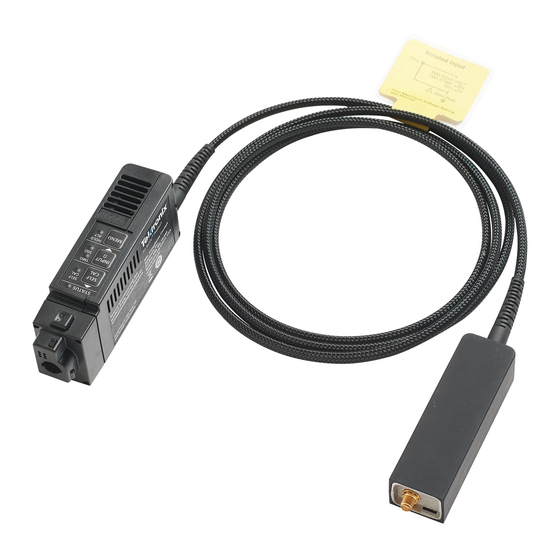
Preface Product description ® The Tektronix IsoVu (TIVP) Generation 2 is a completely galvanically isolated probe tip cable, sensor head, and TekVPI interface as shown in the following figure. Hazardous voltages in the sensor head are completely isolated from the oscilloscope by optical fiber cables. -
Page 22: Models
Supported oscilloscopes The measurement system can be used with the 4, 5, and 6 Series Mixed Signal Oscilloscopes with oscilloscope software version 1.28 or greater. For all other oscilloscopes, contact your local Tektronix representative. Accessories This section lists the standard and optional accessories available for the measurement system. -
Page 23: Optional Accessories
Preface Optional accessories The following table lists optional accessories, such as other sensor tip cables are available. Accessory Description Part number 50X MMCX sensor tip cable TIVPMX50X 100X sensor tip cable with 0.100" spaced square pin connector TIVPSQ100X 500X sensor tip cable with 0.200" spaced wide square pin TIVPWS500X connector 1X MMCX sensor tip cable... -
Page 24: Getting Started
Getting started Getting started Learn about the controls, indicators, and the basic operations of the probe. Operating considerations Read this section before installing your measurement system to be aware of the operating requirements and clearance requirements including possible hazardous areas when the measurement system is connected to the DUT. Measurement system handling best practices The measurement system consists of quality parts and should be treated with care to avoid damage or degrading the performance due to mishandling. -
Page 25: Environmental Requirements
Getting started Environmental requirements The maximum operating environmental ratings for the measurement system when connected to a DUT and a Tektronix oscilloscope. Table 1: Environmental specifications Feature Description Temperature Operating Comp box: 0° C to 40° C Probe head: 0° C to 50° C Tip Cable/Adapters: -40°... -
Page 26: Clearance Requirements
Getting started Clearance requirements The unique common mode voltage range of the measurement system allows it to be used in the presence of high frequency/high voltage common mode signals. It is important to observe all precautions while using this product. Warning: Electrical shock can occur while using this measurement system. -
Page 27: Controls And Indicators
Getting started Controls and indicators A description of the controls and indicators on the compensation box. 1. STATUS indicator. For more information on the state of the LED, see Table 7: STATUS LED descriptions on page 48 2. SELF CAL button and LED indicator: Press to start self-calibration routine. For more information on the state of the LED, see Table 8: SELF CAL LED descriptions on page 48... -
Page 28: Connecting To A Circuit
Getting started Connecting to a circuit Warning: This measurement system contains laser sources; exposing these laser sources may cause laser exposure. Except for the sensor tip cables on the sensor head, do not remove any plastic or metallic covers from the sensor head or comp box or attempt to disassemble the product. -
Page 29: Figure 4: Connecting The Sensor Tip Cable To The Sensor Head
Getting started Figure 4: Connecting the sensor tip cable to the sensor head 4. Connect the sensor head to the included bipod or a similar support. This support keeps the sensor head steady reducing the potential mechanical stresses at the electrical connection point of the DUT. -
Page 30: Self-Calibration
Getting started Self-calibration The TIVP contains a self-calibration function that corrects Gain Accuracy, DC offset, and frequency response. These parameters change as the probe warms up to operating temperature and remains constant once the temperature reaches steady-state. After the probe warms up, self-calibration is recommended when there is a 5°C change in ambient temperature. -
Page 31: Autozero
Getting started Self-calibration takes less than 2 minutes to complete. Your signal does not need to be disconnected from the probe head when running self-calibration. The LED next to the SELF CAL button on the compensation box will flash yellow during the operation. -
Page 32: Menu Button
Getting started Menu button Press the MENU button on the comp box to view the Probe Setup menu on the oscilloscope. Figure 6: Probe Setup menu Use the menu options on the oscilloscope to change the probe settings. Ranges The measurement system has a variety of ranges available for you to select, whether the probe is being used with or without a tip. -
Page 33: Auto Range
Getting started Auto Range In 4, 5, and 6 Series oscilloscopes, the Range Mode is selectable for either Auto Range, or Manual. With the Range Mode set to Auto Range, the probe range is automatically selected when the V/div knob on the oscilloscope is turned. The relationship between probe range and V/div setting matches that shown in Table 2: Ranges and 4/5/6 Series MSO Volts/div settings... -
Page 34: Input Coupling Ac Or Dc
Getting started Input coupling AC or DC The TIVP sensor head contains both DC and DC Reject input coupling modes. By default, DC coupling is enabled; the mode is switchable through the scope interface or PI command. The DC input coupling setting provides a direct, DC coupled, electrical path in the sensor head; it accepts all types of signals, including unchanging DC voltages, time-varying DC voltages, AC, and combinations of AC and DC. -
Page 35: Reference Information
Reference information Reference information Specifications The following tables list the specifications for the measurement system. The specifications are Typical unless noted otherwise. Note: Preliminary specifications are indicated by an asterisk (*) The performance limits in this specification are valid with these conditions: •... - Page 36 Reference information Sensor tip 1 MHz 100 MHz 200 MHz 500 MHz 1 GHz cable TIVPSQ100X 160 dB* 100 dB* 70 dB* 57 dB* 39 dB* 30 dB* TIVPWS500X 160 dB* 100 dB* 60 dB* 48 dB* 33 dB* 25 dB* TIVPMX1X 160 dB* 145 dB*...
-
Page 37: Common Mode Rejection Ratio Graphs
Reference information Common mode rejection ratio graphs The ability to measure common mode rejection ratios (CMRR) of the IsoVu system below 100 kHz is limited by the dynamic range of test systems. Due to the optical isolation of the IsoVu sensor head, the DC CMRR performance of all tip cables is expected to be greater than 160 dB. -
Page 38: Differential Input Impedance Graphs
Reference information Differential input impedance graphs The following figure shows the differential input impedance vs. frequency values for the supported sensor tip cables. Figure 9: Differential input impedance vs. frequency for the sensor tip cables TIVP physical specifications Table 4: Physical specifications Characteristic Description Tip cable assembly: 25g (0.055 lb) -
Page 39: Probe Dimensions
Reference information Probe dimensions Figure 10: Sensor head Figure 11: Sensor tip cable Figure 12: Compensation box TIVP Series IsoVuTM Measurement System User Manual... -
Page 40: Isovu Measurement System Block Diagram
Reference information IsoVu measurement system block diagram The following figure shows a block diagram of the IsoVu measurement system. Figure 13: Block diagram The common mode resistance and capacitance to earth ground is shown in the figure. The common mode resistance is shown as R parasitic and is essentially infinite with the IsoVu measurement system since it is galvanically isolated and can be ignored. -
Page 41: Connecting The Sensor Tip Cables
Figure 15: Connecting to an adapter on the circuit board with the probe tip tripod Installing the probe tip adapters Tektronix provides two probe tip adapters to connect the MMCX sensor tip cables to pins on the circuit board. The MMCX- to-0.1-inch (2.54 mm) pitch adapter and the MMCX-to-0.062-inch (1.57 mm) pitch adapter. -
Page 42: Figure 16: Lining Up The Mmcx-To-0.1-Inch (2.54 Mm) Adapter On The Circuit Board
Reference information To achieve the best electrical performance, especially the CMRR performance and EMI susceptibility, place the probe tip adapter as close as possible to the circuit board. Figure 16: Lining up the MMCX-to-0.1-inch (2.54 mm) adapter on the circuit board Figure 17: Lining up the MMCX-to-0.062-inch (1.57 mm) adapter on the circuit board After lining up the adapters gently push down on the adapter to seat it in place on the circuit board. -
Page 43: Installing The Square Pins On The Circuit Board
Figure 21: Removing the header from square pins on the circuit board Tektronix provides a set of solder pins (0.018-inch (0.46 mm) diameter) to install on the circuit board for use with the MMCX to 0.062-inch (1.57 mm) adapter. Use the soldering aide tool accessory (Tektronix part number, 003-1946-xx) to install these pins on the circuit board. -
Page 44: Figure 22: Using The Soldering Aide To Install The Square Pins On The Circuit Board
Reference information Note: The coaxial (common) shield of the sensor tip cable and tip adapters should always be connected to the lowest impedance point (usually a circuit common or power supply rail) in the circuit-under-test (relative to the sensor tip cable/center conductor) to obtain the most accurate waveform. Use the following steps to install the solder pins using the soldering aide on the circuit board: 1. -
Page 45: User Service
User service Service offerings Tektronix provides service to cover repair under warranty and other services that are designed to meet your specific service needs. Whether providing warranty repair service or any of the other services listed below, Tektronix service technicians are well equipped to service the IsoVu measurement system. -
Page 46: System Rms Noise
User service 2. Connect the TIVP probe to the oscilloscope on CH 1. • Remove any TIVP probe tip, if attached • Attach SMA Male short circuit cap (optional) 3. Allow the test equipment to warm up for 30 minutes at an ambient temperature of about 20 °C. System RMS Noise This procedure verifies that the TIVP Series IsoVu measurement system is functioning and meets the warranted noise specification. -
Page 47: Test Record
User service Test record Use the test record table for recording the results of the performance verification procedures. Table 6: Test record table Model number: Procedure performed by: Serial number: Date: System RMS noise performance check Probe Range Limit Test result TIVP1 20 mV 1 mV RMS... -
Page 48: Troubleshooting And Error Conditions
The following tables describes the state of each LED and lists possible problems that you might encounter when taking measurements with a TIVP Series isolated probe. Use the tables as a quick troubleshooting reference before contacting Tektronix for service. Table 7: STATUS LED descriptions... -
Page 49: Repack The Measurement System For Shipment
Repack the measurement system for shipment If you need to return the measurement system to Tektronix for repair, use the original packaging. If this is unavailable or not fit for use, contact your Tektronix representative to obtain new packaging. -
Page 50: Remote Programming
Remote programming Remote programming This appendix describes commands and queries that can be sent to the sensor head when attached to a Tektronix oscilloscope. Long-form and short-form keywords are indicated with upper/lower case letters. The commands and queries are supported by most oscilloscopes; differences in supporting oscilloscopes, if any, are described with the commands. -
Page 51: Table 12: Probe Tip Cables And Dynamic Ranges
Remote programming CH<x>:PRObe:FORCEDRange The command selects the dynamic range of probe (1 of 9) in +/-V. It is dependent on the attached probe tip. The channel is specified by x. The command should only be used when CH<x>:PROBECONTROL is set to MANUAL. Table 12: Probe tip cables and dynamic ranges Probe tip cable Dynamic Range +/-V... - Page 52 Remote programming CH<x>:PRObe:ID:SERnumber? (Query Only) This query-only command returns the serial number of the probe that is attached to the specified channel. The channel is specified by x. Note: For Level 0 and 1 probes, the serial number will be “N/A”. Syntax CH<x>:PRObe:ID:SERnumber? Examples...
- Page 53 Remote programming CH<x>:PRObe:SET This command sets or queries the probe input resistance for the specified channel. The channel is specified by x. Syntax CH<x>:PRObe:SET {"50ohms ON"|"50ohms OFF"} CH<x>:PRObe:SET? Arguments The text in quotes is not case sensitive. For returns, the case is the same as the last command received.
- Page 54 Remote programming CH<x>:PROBECOntrol This command sets or queries multirange probe range-control policy preference of the probe that is attached to CH<x>. The channel number is specified by x. Syntax CH<x>:PROBECOntrol {AUTO|MANual} CH<x>:PROBECOntrol? Arguments AUTO sets the values. The probe range is automatically calculated. MANual allows you to select various valid values for the probe connected to a particular channel.
- Page 55 Remote programming Syntax CH<x>:PROBEFunc:EXTUnits <QString> CH<x>:PROBEFunc:EXTUnits? Arguments <QString> indicates the attenuation unit of measurement for the specified channel. Examples CH4:PROBEFUNC:EXTUNITS "Pascals" sets the unit of measurement for the Channel 4 external attenuator. CH2:PROBEFUNC:EXTUNITS? might return "Pascals", indicating that the Channel 2 external attenuator unit of measurement is Pascals. CH<x>:PROBEFunc:EXTUnits:STATE This command sets or queries the custom units enable state for the specified channel.
-
Page 56: Index
Index accessories laser certification optional standard Auto Range measurement system setup menu button MMCX connectors bend radius models fiber-optic cables sensor tip cables block diagram operating requirements optional accessories cable care cable flags cable handling practices packaging CMRR performance verification common mode rejection ratios procedures comp box... - Page 57 specifications square pin adapters square pin connectors standard accessories supported oscilloscopes test record TIVP02 TIVP05 TIVP1 troubleshooting user service voltage vs. frequency derating graphs warranty repair service...
Need help?
Do you have a question about the IsoVu TIVP Series and is the answer not in the manual?
Questions and answers