Sign In
Upload
Manuals
Brands
Tektronix Manuals
Measuring Instruments
IsoVu TIVP02L
Tektronix IsoVu TIVP02L Manuals
Manuals and User Guides for Tektronix IsoVu TIVP02L. We have
2
Tektronix IsoVu TIVP02L manuals available for free PDF download: User Manual, Quick Reference Manual
Tektronix IsoVu TIVP02L User Manual (57 pages)
Brand:
Tektronix
| Category:
Measuring Instruments
| Size: 10 MB
Table of Contents
Table of Contents
5
List of Figures
7
Warranty
9
Tektronix End User License Agreement
10
Third Party Software Licenses
14
Important Safety Information
16
General Safety Summary
16
To Avoid Fire or Personal Injury
16
Sensor Tip Cables
17
Terms in this Manual
17
Symbols and Terms on the Product
17
Compliance Information
18
Safety Compliance
18
Environmental Considerations
19
Preface
20
Key Features
20
Laser Certification
20
Product Description
21
Compensation Box
21
Sensor Head
21
Sensor Tip Cables
21
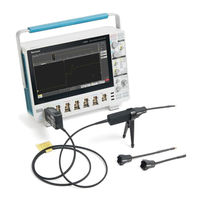
Figure 1: TIVP Series Isovu Measurement System
21
Models
22
Supported Oscilloscopes
22
Accessories
22
Standard Accessories
22
Optional Accessories
23
Getting Started
24
Operating Considerations
24
Measurement System Handling Best Practices
24
Environmental Requirements
25
Table 1: Environmental Specifications
25
Clearance Requirements
26
Figure 2: Maximum Safe Handling Limits for Common Mode Voltages between the Sensor Head and Earth Ground
26
Figure 3: RF Burn Hazard Zone Around the Sensor Head
26
Controls and Indicators
27
Cable Flags
27
Sensor Tip Cable
27
Connecting to a Circuit
28
Figure 4: Connecting the Sensor Tip Cable to the Sensor Head
29
Figure 5: Connect the Sensor Head to the Bipod
29
Self-Calibration
30
Autozero
31
Menu Button
32
Ranges
32
Figure 6: Probe Setup Menu
32
Table 2: Ranges and 4/5/6 Series MSO Volts/DIV Settings
32
Auto Range
33
Selecting a Sensor Tip Cable
33
Deskew
33
Input Offset
33
Table 3: Sensor Tip Cable Selection
33
Input Coupling AC or DC
34
Voltage Range
34
Common Mode Voltage Range
34
Offset Voltage Range
34
Maximum Non-Destruct Differential Voltage Range
34
Reference Information
35
Specifications
35
Overview
35
Common Mode Rejection Ratio Graphs
37
Maximum Differential Input Voltage Vs Frequency Derating Graphs
37
Figure 7: Typical CMRR Values for the Sensor Tip Cables
37
Figure 8: Maximum Differential Input Voltage Vs. Frequency for the Sensor Tip Cables
37
Differential Input Impedance Graphs
38
TIVP Physical Specifications
38
Figure 9: Differential Input Impedance Vs. Frequency for the Sensor Tip Cables
38
Table 4: Physical Specifications
38
Probe Dimensions
39
Figure 10: Sensor Head
39
Figure 11: Sensor Tip Cable
39
Figure 12: Compensation Box
39
Isovu Measurement System Block Diagram
40
Figure 13: Block Diagram
40
Connecting the Sensor Tip Cables
41
Probe Tip Tripod
41
Installing the Probe Tip Adapters
41
Figure 14: Square Pin Series Sensor Tip Cables
41
Figure 15: Connecting to an Adapter on the Circuit Board with the Probe Tip Tripod
41
Figure 16: Lining up the MMCX-To-0.1-Inch (2.54 MM) Adapter on the Circuit Board
42
Figure 17: Lining up the MMCX-To-0.062-Inch (1.57 MM) Adapter on the Circuit Board
42
Figure 18: Pushing the MMCX-To-0.062-Inch (1.57 MM) Adapter in Place
42
Figure 19: Pushing the MMCX-To-0.1-Inch (2.54 MM) Adapter in Place
42
Installing the Square Pins on the Circuit Board
43
Figure 20: Adapter Clearance Requirements
43
Figure 21: Removing the Header from Square Pins on the Circuit Board
43
Figure 22: Using the Soldering Aide to Install the Square Pins on the Circuit Board
44
User Service
45
Service Offerings
45
Warranty Repair Service
45
Calibration and Repair Service
45
Preventive Maintenance
45
Performance Verification Procedures
45
Required Equipment
45
Preparation
45
Table 5: Required Equipment for Performance Verification
45
System RMS Noise
46
Setup the Measurement System
46
Perform the Measurement
46
Test Record
47
Table 6: Test Record Table
47
Troubleshooting and Error Conditions
48
Table 7: STATUS LED Descriptions
48
Table 8: SELF CAL LED Descriptions
48
Table 9: INPUT LED Descriptions
48
Table 10: ALT Mode LED Description
48
Repack the Measurement System for Shipment
49
Table 11: Measurement Problems and Possible Solutions
49
Remote Programming
50
Command List
50
Table 12: Probe Tip Cables and Dynamic Ranges
51
Index
56
Advertisement
Tektronix IsoVu TIVP02L Quick Reference Manual (2 pages)
Brand:
Tektronix
| Category:
Measuring Instruments
| Size: 0 MB
Advertisement
Related Products
Tektronix IsoVu TIVP02
Tektronix IsoVu TIVP05
Tektronix IsoVu TIVP1
Tektronix IsoVu TIVP05L
Tektronix TIVP Series
Tektronix IsoVu TIVM05
Tektronix IsoVu TIVM05L
Tektronix TIVH02
Tektronix TIVH05
Tektronix TIVH02L
Tektronix Categories
Test Equipment
Measuring Instruments
Amplifier
Portable Generator
Printer
More Tektronix Manuals
Login
Sign In
OR
Sign in with Facebook
Sign in with Google
Upload manual
Upload from disk
Upload from URL