Advertisement
Quick Links
xx
TIVP IsoVu™ Measurement System
Quick Reference Guide
*P071373300*
071-3733-00
Operating information
The Tektronix TIVP IsoVu™ Measurement System offers a
completely galvanically isolated (optical isolation) system.
Isolation is used to greatly increase the accuracy of differential
measurements with rapidly slewing reference voltages and to
isolate hazardous voltages from the oscilloscope.
The TIVP is designed for use with Tektronix 4/5/6 Series MSO
Oscilloscopes running software version 1.28 or higher.
Refer to the TIVP User Manual (071-3692-xx) for complete
operating information and product specifications. The manual
is available for download at www.tek.com/downloads.
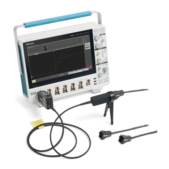
The following illustration shows how to connect the probe to
your instrument and the controls on the compensation box.
Controls and indicators
1. STATUS indicator.
LED
Status
Action
-
Green (Solid)
Normal operation
Green
Bulk power failure Try unplugging and plugging
(Blinking)
back in. Inspect probe/scope
interface. Service of probe
may be required.
Red (Solid)
Probe application
Try unplugging and plugging
failure
back in. Service of probe
may be required.
Red
Probe application
Try unplugging and plugging
(Blinking)
failure and bulk
back in. Inspect probe/scope
power failure
interface. Service of probe
and/or scope may be
required.
Red
Self-Test failure
Try unplugging and plugging
(Blinking • • – )
back in. Service of probe
No Power to probe
may be required.
head
x
2. SELF CAL button and LED indicator. Press to start
self-calibration routine.
LED
Status
Green (Solid)
Self-calibration completed successfully
Amber
Self-calibration currently in progress
(Intermittent flashing)
Red (Solid)
Self-calibration failed
Amber (Solid)
Self-calibration recommended
Internal probe temperatures or other settings
have invalidated the previous Self Cal.
3. INPUT Termination button and LED indicator. With no tip
attached, press to toggle the sensor head between 50 Ω and 1
MΩ termination.
LED
Status
50 Ω
Sensor head SMA connector is terminated in 50 Ω ±5 V
input range
1 MΩ Sensor head SMA connector is terminated in 1 MΩ
±5 V input range
Neither
Sensor head has tip attached (switching input
termination disabled)
4. MENU button. Press to open the Probe Vertical menu on
the oscilloscope.
5. ALT Mode indicator.
LED
Status
Magenta
The probe compensation box is near its maximum
(Flashing)
operating temperature. Additional cooling, such as
an external fan, may be required.
Compensating the probe
The TIVP contains a self-calibration routine that corrects
Gain Accuracy, DC offset, and frequency response. These
parameters change as the probe warms up to its operating
temperature and remain constant once the temperature reaches
steady-state. An indicator LED on the probe compensation
box and the SELFCAL:STATE? PI command both indicate
whether a self-calibration is RECOMMENDED, RUNNING,
or PASSED.
Before making critical measurements, run SELF CAL to
ensure the TIVP is compensated. The sensor tip does not need
to be removed from the test point to successfully complete
a self-calibration.
1.
Connect TIVP to an oscilloscope channel.
2.
Press the SELF CAL button on the probe compensation
box. Alternatively, send the CH<x>:PROBE:SELFCAL
EXECUTE PI command to start the self-calibration
programmatically.
The SELF CAL LED will blink while the
self-calibration is in process.
The SELF CAL LED is amber when there is a change
and a self-calibration is recommended. The LED is
green if the last self-calibration is still valid.
Cable handling
Tektronix TIVP probes operate using several optical fibers
within a single cable between the compensation box and probe
head. Therefore, standard optical fiber handling practices
are required. Avoid tight radius bends, crushing, crimping,
twisting, or otherwise stressing the fiber.
Standard accessories
MMCX probe tip
The 10X MMCX tip is included in every TIVP probe. The MMCX tip is
recommended for the best bandwidth and CMRR performance. 0.100"
Square Pin and 0.200" Wide Square Pin tips are available as optional
accessories. Reorder part number: TIVPMX10X
Probe bipod
Used to hold probe. TIVP can
rotate in holder to accommodate
square pin headers. Reorder part
number:
352-1179-xx
Probe tip adapter
Adapt an MMCX IsoVu tip to
standard 0.100" spaced, 0.025"
square pins. Reorder part number:
131-9717-xx
SMA wrench/driver tool
5/16" wrench for use on SMA
connector. Reorder part number:
003-1947-xx
IsoVu carrying case
Soft case (with foam insert)
protects the TIVP and enforces the
optical fiber minimum bend radius.
Reorder part number:
016-2147-xx
Optional accessories
50X MMCX sensor tip
TIVPMX50X
100X sensor tip cable with 0.100" spaced square pin connectors
TIVPSQ100X
500X sensor tip cable with 0.200" spaced wide square pin connector
TIVPWS500X
1X MMCX sensor tip
TIVPMX1X
Square Pin to MMCX Adapter,
0.062" Spacing
131-9677-xx
Probe Tip Tripod Support
352-1170-xx
Lead, MMCX to IC Grabber
196-3546-xx
Lead, Square Pin to IC Grabber
196-3547-xx
Lead, Wide Square Pin to Banana
Jack
020-3189-xx
MMCX Y-Lead
TPR4KIT
Square Pin Y-lead
196-3434-xx
MicroCKT grabbers
206-0569–xx
Spare Pins for 0.062" Spaced Test
Points
020-3169-xx
Solder Aid for 0.062" Spaced
Square Pins
003-1946-xx
Clearance requirements
The unique common mode voltage range
of the measurement system allows it to be
used in the presence of high frequency/high
voltage common mode signals. It is
important to observe all precautions while
using this product.
WARNING.
Electrical shock can occur while using this
measurement system. The system is intended to isolate the
operator from hazardous input voltages (common voltages);
the plastic case of the sensor head and the shield on the
sensor tip cable do not supply safe isolation. Maintain the
safe clearance from the sensor head and sensor tip cable
while the measurement system is connected to the energized
circuit as recommended in this document. Do not access the
RF Burn Hazard Zone while taking measurements on a live
circuit. RF burn hazard zone is 1 meter (40 in) on all sides
Specifications
Table 1: Physical specifications
Characteristic
Description
Net weight
Tip cable assembly: 25g (0.055 lb)
(Weight does not
Probe head: 0.363 kg (0.8 lbs)
include accessories
Compensation box: 0.816kg (1.8lbs)
and packaging.)
Sensor tip cable length 20.03 cm (7.886 inches)
Fiber cable length
2 meter (6.56 ft)
Table 2: Electrical specifications
Preliminary specifications are indicated by an asterisk (*)
Characteristic
Description
Maximum
SMA Input
5 Vrms, (DC + peak AC)
Non-Destructive
(50 Ω mode)
Input Voltage
SMA Input
100 Vpk
(Typical)
(1 MΩ mode)
TIVPMX10X
250 Vpk
TIVPMX50X
300 Vpk*
TIVPSQ100X
600 Vpk*
TIVPWS500X
3300 Vpk*
TIVPMX1X
5 V RMS (50 Ω), 100 Vpk (1 MΩ)
Advertisement

Related Manuals for Tektronix IsoVu TIVP02


Summary of Contents for Tektronix IsoVu TIVP02
- Page 1 The SELF CAL LED is amber when there is a change and a self-calibration is recommended. The LED is The TIVP is designed for use with Tektronix 4/5/6 Series MSO Clearance requirements green if the last self-calibration is still valid.
- Page 2 Equipment type Preliminary specifications are indicated by an asterisk (*) connected to a voltage source. Use only test leads and accessories supplied with the product, or indicated by Tektronix Test and measuring equipment. CLASS 1 LASER PRODUCT. Characteristic Description to be suitable for the product.
Need help?
Do you have a question about the IsoVu TIVP02 and is the answer not in the manual?
Questions and answers