Tektronix WVR5200 Service Manual
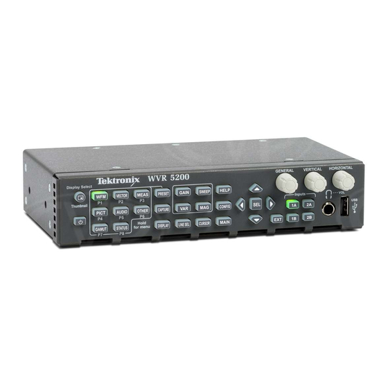
Waveform rasterizer
Hide thumbs
Also See for WVR5200:
- Specification and performance verification technical reference (72 pages) ,
- Installation and safety manual (65 pages) ,
- Technical reference (28 pages)
Table of Contents
Advertisement
Quick Links
Download this manual
See also:
Instruction Manual
Advertisement
Table of Contents
Troubleshooting

Related Manuals for Tektronix WVR5200


Summary of Contents for Tektronix WVR5200
- Page 1 WVR5200 Waveform Rasterizer Service Manual *P077055100* 077-0551-00...
- Page 3 WVR5200 Waveform Rasterizer Service Manual www.tektronix.com 077-0551-00...
- Page 4 Copyright © Tektronix. All rights reserved. Licensed software products are owned by Tektronix or its subsidiaries or suppliers, and are protected by national copyright laws and international treaty provisions. Tektronix products are covered by U.S. and foreign patents, issued and pending. Information in this publication supersedes that in all previously published material.
- Page 5 Tektronix, with shipping charges prepaid. Tektronix shall pay for the return of the product to Customer if the shipment is to a location within the country in which the Tektronix service center is located. Customer shall be responsible for paying all shipping charges, duties, taxes, and any other charges for products returned to any other locations.
-
Page 7: Table Of Contents
Detailed Troubleshooting Procedures ..............Removal and Replacement Procedures ................. Preparation..................... Module Removal....................Repackaging Instructions ..................Packaging ...................... Shipping to the Service Center ................Replaceable Parts ....................Parts Ordering Information .................. Using the Replaceable Parts Lists................WVR5200 Waveform Rasterizer Service Manual... - Page 8 Table of Contents List of Figures Figure 1: Block diagram ..................Figure 2: SDI board ....................Figure 3: Fan and main chassis .................. Figure 4: WVR5200 Exploded view ................WVR5200 Waveform Rasterizer Service Manual...
- Page 9 Table 1: External inspection check list................Table 2: Internal inspection check list................Table 3: Required test equipment................Table 4: Symptoms and causes .................. Table 5: SDI board basic supplies ................Table 6: Tools required for module removal ..............WVR5200 Waveform Rasterizer Service Manual...
-
Page 10: General Safety Summary
Do not operate in wet/damp conditions. Do not operate in an explosive atmosphere. Keep product surfaces clean and dry. Provide proper ventilation. Refer to the manual's installation instructions for details on installing the product so it has proper ventilation. WVR5200 Waveform Rasterizer Service Manual... - Page 11 DANGER indicates an injury hazard immediately accessible as you read the marking. WARNING indicates an injury hazard not immediately accessible as you read the marking. CAUTION indicates a hazard to property including the product. The following symbol(s) may appear on the product: WVR5200 Waveform Rasterizer Service Manual...
-
Page 12: Service Safety Summary
Use Care When Servicing With Power On. Dangerous voltages or currents may exist in this product. Disconnect power, remove battery (if applicable), and disconnect test leads before removing protective panels, soldering, or replacing components. To avoid electric shock, do not touch exposed connections. WVR5200 Waveform Rasterizer Service Manual... -
Page 13: Preface
Preface This manual supports servicing to the module level of the WVR5200 Waveform Rasterizer, which rasterizes video signals for XGA display. The instrument finds use as a monitor for broadcasting, production, and post-production environments. This manual explains how to troubleshoot and service the instrument to the module level. - Page 14 Specifications and Performance list of specifications www.tektronix.com/manuals Verification WFM Series Waveform Monitors and Programmer’s command reference for Product Documentation CD WVR Series Waveform Rasterizers controlling the waveform rasterizer www.tektronix.com/manuals Management Information Base Programmer Manual viii WVR5200 Waveform Rasterizer Service Manual...
-
Page 15: Introduction
Manuals.) Options and Accessories The lists of options and accessories for this product are found in the WVR5200 Waveform Rasterizer User Manual located on the Product Documentation CD that ships with the product and is published on the Tektronix Web site. (See page vii, Related Manuals.) -
Page 16: Product Upgrade
Product Upgrade Software upgrades are available for all products as free software downloads from the Tektronix Web site. The WVR5200 Waveform Rasterizer User Manual includes instructions for updating product software. If you would like to purchase additional features and capabilities for your instrument, contact Tektronix for more information on purchasable options. -
Page 17: Theory Of Operation
CPU board at the bottom, the SDI board in the center, and the FPGA board at the top. Connectors to the External Reference and Front Panel boards are shown. Power Distribution is not shown in the block diagram but is covered at the end of this section. WVR5200 Waveform Rasterizer Service Manual... -
Page 18: Figure 1: Block Diagram
Theory of Operation Figure 1: Block diagram WVR5200 Waveform Rasterizer Service Manual... -
Page 19: Cpu Board
SPI or the I C bus. The control processor interfaces to the Ethernet through a dual rate connection. This allows the network connection to run at 10 or 100 MBps. WVR5200 Waveform Rasterizer Service Manual... -
Page 20: Front Panel
On the second path, raw data samples are sent to the waveform processing engine, which interpolates and plots it to generate the lissajous, or “phase,” display. WVR5200 Waveform Rasterizer Service Manual... -
Page 21: Fan Control
A latching relay controls standby mode. The nominal 12 V DC input powers 5 V and 3.3 V supplies. All three voltages are distributed to the CPU and FPGA boards to power circuits as well as lower voltage local regulators. WVR5200 Waveform Rasterizer Service Manual... - Page 22 Theory of Operation WVR5200 Waveform Rasterizer Service Manual...
-
Page 23: General Maintenance
Do service of static-sensitive modules only at a static-free work station. 4. Nothing capable of generating or holding a static charge should be allowed on the work station surface. 5. Handle circuit boards by the edges when possible. WVR5200 Waveform Rasterizer Service Manual... -
Page 24: Inspection And Cleaning
Use only deionized water when cleaning the front-panel buttons. Use a 75% isopropyl alcohol solution as a cleaner and rinse with deionized water. Before using any other type of cleaner, consult your Tektronix Service Center or representative. WVR5200 Waveform Rasterizer Service Manual... -
Page 25: Table 1: External Inspection Check List
Burned circuit boards. Burned, broken, or cracked circuit-run plating. Resistors Burned, cracked, broken, Remove and replace blistered condition. damaged circuit board. Solder connections Cold solder or rosin joints. Resolder joint and clean with isopropyl alcohol. WVR5200 Waveform Rasterizer Service Manual... - Page 26 5. Spray wash dirty parts with the isopropyl alcohol and wait 60 seconds for the majority of the alcohol to evaporate. 6. Dry all parts with low-pressure, deionized air. Lubrication. There is no periodic lubrication required for the instrument. WVR5200 Waveform Rasterizer Service Manual...
-
Page 27: Troubleshooting
Unknown Problem section in the Symptoms and Causes table. The WVR5200 Waveform Rasterizer is highly configurable, and its behavior is sometimes complex. Before troubleshooting in-depth, verify that: The installed options are as expected. See CONFIG > Utilities > View Instrument Options The current settings support the expected behavior. -
Page 28: Table 3: Required Test Equipment
Requirements Example SDI serial digital video test generator with 1080p 59.94 3 Gb/s signals required: Tektronix TG700 with an HD3G7 module embedded audio. Instruments with option (Embedded audio needed for audio 100% color bars 3G require a 3 Gb/s SDI source. -
Page 29: Table 4: Symptoms And Causes
Replace FPGA board USB bad Replace CPU board Ethernet bad Replace CPU board Fans bad Perform Fan checks Headphones bad, audio bars Replace CPU board Reference or LTC waveform Check Reference I/O cable Replace Reference I/O board WVR5200 Waveform Rasterizer Service Manual... -
Page 30: Detailed Troubleshooting Procedures
If S1 causes normal power up (indicated by lit red and green LEDs on the CPU board), then the problem is in the connection from the front panel button to the SDI board. Disconnect power, disassemble as necessary, and check for continuity or low resistance of the following links: WVR5200 Waveform Rasterizer Service Manual... -
Page 31: Table 5: Sdi Board Basic Supplies
SDI board. If voltages are within the allowed range, replace the CPU board. Table 5: SDI board basic supplies Nominal (+V) Allowed range (+V) +12V 11 to 17 4.85 to 5.15 +3.3V 3.2 to 3.4 WVR5200 Waveform Rasterizer Service Manual... -
Page 32: Figure 2: Sdi Board
Troubleshooting Figure 2: SDI board WVR5200 Waveform Rasterizer Service Manual... - Page 33 Observe the sequence of front panel button illumination at power on. Normal power up sequence has the following appearance. Time “T” is in seconds. T=0 : press power button to power up WVR5200 Waveform Rasterizer Service Manual...
- Page 34 If a fan is not spinning, measure the voltage on pin 1 of the connector on that fan. If the voltage is near 13 V, then replace the fan. If the voltage is not above 10 V, then replace the CPU board. WVR5200 Waveform Rasterizer Service Manual...
- Page 35 2. If the buttons are not lit, check the 10 pin cable from the keypad to the main board J21. If the cable is connected and good, then replace the front panel assembly. WVR5200 Waveform Rasterizer Service Manual...
-
Page 36: Removal And Replacement Procedures
(See Table 6 on page 23.) Read the cleaning procedure before disassembling the instrument for cleaning. Equipment Required. Most modules in the instrument can be removed with a screwdriver handle mounted with a size T8 and T10 Torx screwdriver tips and a WVR5200 Waveform Rasterizer Service Manual... -
Page 37: Table 6: Tools Required For Module Removal
MA-800G Soldering Aid Used to remove the front panel trim Standard tool (spudger) Soldering iron (15 W) Used for replacing CPU board Standard tool fuses Long nose pliers Used to compress connector lock Standard tool tabs WVR5200 Waveform Rasterizer Service Manual... -
Page 38: Module Removal
2. Remove the nut and lock washers from the two Ref Loop female BNC connectors using a 9/16 wrench. 3. Pull the Reference board straight back away from the rear panel. 4. Place the Reference board on a static-free work surface. WVR5200 Waveform Rasterizer Service Manual... - Page 39 T-10 screws on the bottom that secure the front panel assembly to the main chassis. 2. Pull the front panel assembly forward. Gently pull the cable through the slot in the main chassis. 3. Gently disconnect the cable from the front panel board and set it aside. WVR5200 Waveform Rasterizer Service Manual...
-
Page 40: Figure 3: Fan And Main Chassis
Make sure the fans are rotated so that the cables are located up against the main chassis bottom and on the outer corners. (See Figure 3.) Figure 3: Fan and main chassis WVR5200 Waveform Rasterizer Service Manual... -
Page 41: Repackaging Instructions
Type and serial number of the instrument. Reason for returning. A complete description of the service required. Mark the address of the Tektronix Service Center and the return address on the shipping carton in two prominent locations. WVR5200 Waveform Rasterizer Service Manual... - Page 42 Repackaging Instructions WVR5200 Waveform Rasterizer Service Manual...
-
Page 43: Replaceable Parts
For more information about the module exchange program, call 1-800-833-9200. Outside North America, contact a Tektronix sales office or distributor; see the Tektronix Web site for a list of offices: www.tektronix.com. Module Repair and Return. You may ship your module to us for repair, after which we will return it to you. -
Page 44: Using The Replaceable Parts Lists
Orderable modules show the figure number without an index number. Tektronix part number Use this part number when ordering replacement parts from Tektronix. 3 and 4 Serial number Column three indicates the serial number at which the part was first effective. - Page 45 174-5492-00 CABLE ASSEMBLY, 10 PIN; FP TO MAIN; ROHS TO ROHS. 863-6505-01 CIRCUIT BOARD SUBASSY;WVR FP 260-2923-00 SWITCH KEYPAD (ELASTOMER MAT WVR) 333-4649-00 FRONT PANEL ASSEMBLY, FRONT PANEL 366-0859-00 ASSEMBLY, KNOB; .470 DIAMETER, SOFT TOUCH WVR5200 Waveform Rasterizer Service Manual...
-
Page 46: Figure 4: Wvr5200 Exploded View
Replaceable Parts Figure 4: WVR5200 Exploded view WVR5200 Waveform Rasterizer Service Manual...
Need help?
Do you have a question about the WVR5200 and is the answer not in the manual?
Questions and answers