Advertisement
HOW TO USE THE GL100 WITH GS DPA-AC CURRENT SENSORS
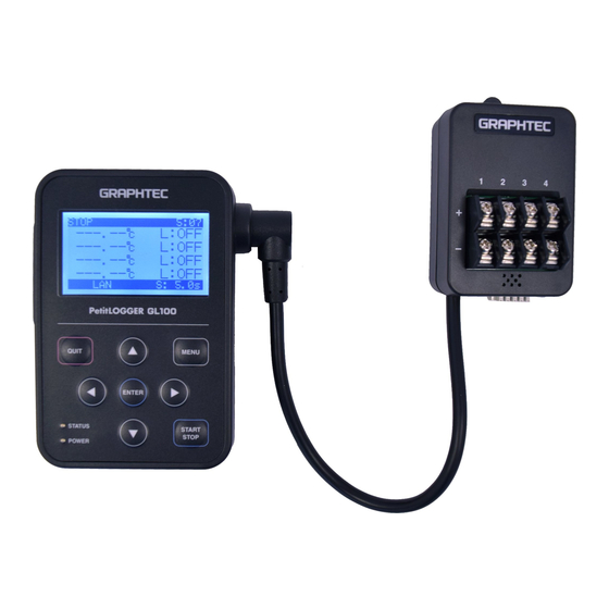
Installation brief for GL100 Power Monitoring Solution
Tips for sensor mounting
Tip of the sensor mounting
Connect the AC Current Sensor (GS DPA-AC, sold separately)
1. Connect the AC Current Sensor (GS-AC**A, sold separately) (1) Recording to the module.
Connecting
: Push the connector in until it locks in.
Disconnecting
: Pull the connector out while pressing down on the lock on the bottom with your finger.
Connector cable
The connector is exclusively used to connect the AC current sensor. Do not connect it directly to
The connector is exclusively to be used to connect the AC Current Sensor. Do not connect it to voltages,
voltage, or other electrical currents, etc.
other electrical currents, etc. It will damage the module.
Pulling the AC Current Sensor's cable and holding the sensor by the cable will damage the cable's wires.
Do not pull the AC current sensor cable from the adapter. Press the lock mechanism to unlock the clamps.
2. How to measure with AC Current Sensor
Remove the AC current sensor's lock, insert the measurement cable and push it in until it locks down
Remove the AC Current Sensor's lock, insert the measurement cable and push it in until it locks (putting the cable in
(putting the cable in the wrong way will cause the module to measure incorrectly).
the wrong way will cause the module to measure incorrectly).
Unlock
* It may be damaged when lifting
* It may damage when lock
mechanism is lifted more than
more than necessary the hook,
necessary, please use caution.
so please use caution.
Clamp ch1 or ch2 to L-phase when using single-phase 2-wire
Clamp ch1 and ch2 to R-phase and S-phase respectively when using single-phase 3-wire.
Clamp ch1 and ch2 to R-phase and T-phase respectively when using 3-phase 3-wire.
< Single-phase 2-wire >
Load side (L)
L
Power side (K)
Power side (K)
Example of wiring
< Single-phase 3-wire >
Load side (L)
N
R
N
Power side (K)
AC Current Sensor
Load side (L)
Insert the cable and
push it in until it clicks.
< 3-phase 3-wire >
Load side (L)
S
R
S
Power side (K)
CHAPTER 2 Checks and Preparation
T
Advertisement
Table of Contents

Related Manuals for GRAPHTEC GL100


Summary of Contents for GRAPHTEC GL100
- Page 1 HOW TO USE THE GL100 WITH GS DPA-AC CURRENT SENSORS CHAPTER 2 Checks and Preparation Installation brief for GL100 Power Monitoring Solution Tips for sensor mounting Tip of the sensor mounting Connect the AC Current Sensor (GS DPA-AC, sold separately) 1. Connect the AC Current Sensor (GS-AC**A, sold separately) (1) Recording to the module.
- Page 2 CHAPTER 2 Checks and Preparation Tips for settings Tip of Settings 1. Various settings In AMP setting screen, select the measurement mode. Next select the sensor type to be used and then set the In AMP setting screen, select the measurement mode. Next select sensor type and then set the measurement voltage and power factor.
- Page 3 2. Example of measurement Measurement with single-phase 100V, 2 loads When the following connection is established, each current measurement for I, Ia, and Ib is possible. (The clamp in the following figure indicates the measurement point of AC current sensor.) the displayed data does not necessarily follow l = la + lb However, when measured by the GL100, it is not necessarily I = Ia + Ib (Since it is calculated in vector quantity.). (since the results are calculated in vector quantity.). Clamp 1 Clamp 2 Clamp 3 100V Single-phase 3-wire (100V and 200V) (The clamp in the following figure indicates the measurement point of AC current sensor.)
- Page 4 CHAPTER 2 Checks and Preparation 3) How to measure with three-phase 3-wire (The clamp in the following figure indicates the measurement point of AC current sensor.) Blondel's theorem: “When the number of electrical conductors is n, the multi-phase power can be measured by the watt-meter (n-1)”. The Δ-connection and Y-connection are described below. The current effective value of R and T power line are measured at the clamp 1 and 2. Using the Blondel's theorem, the GL100 calculates the power with the following formula. Power = ((Measured current (CH1) + Measured current (CH2))÷2) x Set voltage x √3 x Set power factor Measurement method: Measured at the clamp 1 (CH1) and clamp 2 (CH2) in three-phase 3-wire (AC3 3W) mode. The effective current value of R (U) phase is measured at clamp 1 (CH1), and effective current value of T (W) The current effective value of R (U) phase is measured at the clamp 1 (CH1), and the current effective value of T (W) phase is measured at the clamp 2 (CH2). phase is measured at clamp 2 (CH2).
- Page 5 CHAPTER 2 Checks and Preparation Display screen In display screen The instantaneous power is displayed only during free-running mode. The instantaneous power only is displayed during free-running. • Accumulated Value During recording, you can switch to accumulated value During recording, you can switch to the accumulation screen by operating [ ] and [ ] keys. REC. ALM. 1:28 STOP ALM. 1:28 1.AC(A): 105.08A 1.AC(A):105.08A PWR. 10.51kw PWR. 10.51kwh 2.AC(A): 105.08A 2.AC(A):105.08A PWR. 10.51kw PWR. 10.51kwh BAT LAN SD S: 1.0s BAT LAN SD S: 1.0s Normal display Accumulated value display How to clear the accumulated value...
Need help?
Do you have a question about the GL100 and is the answer not in the manual?
Questions and answers