Sign In
Upload
Manuals
Brands
WAGO Manuals
Control Unit
750-528
User Manuals: WAGO 750-528 4-channel digital output
Manuals and User Guides for WAGO 750-528 4-channel digital output. We have
1
WAGO 750-528 4-channel digital output manual available for free PDF download: Manual
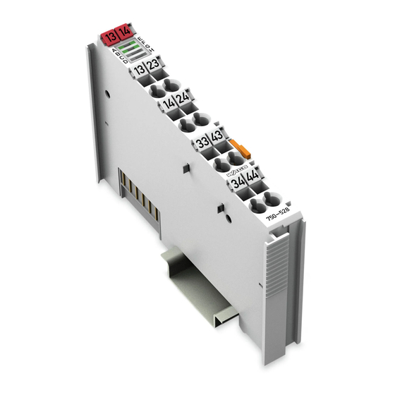
WAGO 750-528 Manual (50 pages)
4DO 30V AC/DC 2.0A SSR Isolated 4-Channel Digital Output, 30 VAC/DC, 2.0 A, Solid-State, Isolated for WAGO-I/O-SYSTEM 750 Series
Brand:
WAGO
| Category:
Control Unit
| Size: 2 MB
Table of Contents
Table of Contents
3
1 Notes about this Documentation
5
Validity of this Documentation
5
Copyright
5
Symbols
6
Number Notation
8
Font Conventions
8
Table 1: Number Notation
8
Table 2: Font Conventions
8
2 Important Notes
9
Legal Bases
9
Subject to Changes
9
Personnel Qualifications
9
Use of the 750 Series in Compliance with Underlying Provisions
9
Technical Condition of Specified Devices
10
Safety Advice (Precautions)
11
3 Device Description
15
View
16
Figure 1: View
16
Table 3: Legend for Figure "View
16
Connectors
17
Data Contacts/Local Bus
17
Figure 2: Data Contacts
17
Power Jumper Contacts/Field Supply
18
Figure 3: Power Jumper Contacts
18
Table 4: Legend for Figure "Power Jumper Contacts
18
CAGE CLAMP ® Connectors
20
Figure 4: CAGE CLAMP ® Connectors
20
Table 5: Legend for Figure "CAGE CLAMP ® Connectors
20
Display Elements
21
Schematic Diagram
21
Figure 5: Display Elements
21
Figure 6: Schematic Diagram
21
Table 6: Legend for Figure "Display Elements
21
Technical Data
22
Device Data
22
Digital Outputs
22
Table 7: Technical Data - Device
22
Table 8: Technical Data - Digital Outputs
22
Field Supply
23
Local Bus Supply
23
Isolation
23
Communication
23
Connection Type
23
Table 9: Technical Data − Field Supply
23
Table 10: Technical Data - Local Bus Supply
23
Table 11: Technical Data - Isolation
23
Table 12: Technical Data - Communication
23
Table 13: Technical Data - Field Wiring
23
Environmental Conditions
24
Table 15: Technical Data - Data Contacts
24
Table 16: Environmental Conditions
24
Approvals
25
Standards and Guidelines
26
4 Process Image
27
Table 17: Output Bits
27
5 Mounting
28
Mounting Sequence
29
Inserting and Removing Devices
30
Inserting the I/O Module
30
Figure 7: Inserting I/O Module (Example)
30
Figure 8: Snap the I/O Module into Place (Example)
30
Removing the I/O Module
31
Figure 9: Removing the I/O Module (Example)
31
6 Connect Devices
32
Connecting a Conductor to the CAGE CLAMP
32
Figure 10: Connecting a Conductor to a CAGE CLAMP
32
Power Supply Concept
33
Power Supply for Voltage Ranges up to 31.2 VDC
33
Figure 11: Power Supply
33
Table 18: Legend for Figure "Power Supply
33
Power Supply for AC Voltage (up to 30 VAC) or DC Voltage above 31.2 V (up to 48 VDC)
34
Connection Examples
35
Figure 12: Connection Example, 4 Separate Circuits
35
Figure 13: Connection Example, 2 Interconnected Circuits each
35
7 Use in Hazardous Environments
36
Marking Configuration Examples
37
Marking for Europe According to ATEX and Iecex
37
Figure 14: Marking Example Per ATEX and Iecex
37
Figure 15: Text Detail - Marking Example Per ATEX and Iecex
37
Table 19: Description of the Marking Example Per ATEX and Iecex
38
Figure 16: Marking Example of an Approved I/O Module Ex I Per ATEX and
39
Figure 17: Text Detail - Marking Example of an Approved I/O Module Ex I
39
Table 20: Description of the Marking Example of an Approved I/O Module Ex I Per ATEX and Iecex
40
Marking for the United States of America (NEC) and Canada (CEC)
41
Figure 18: Marking Example According to NEC
41
Figure 19: Text Detail - Marking Example According to NEC 500
41
Table 21: Description of Marking Example According to NEC 500
41
Figure 20: Text Detail - Marking Example for Approved Ex I I/O Module
42
Figure 21: Text Detail - Marking Example for Approved Ex I I/O Module
42
Table 22: Description of Marking Example for Approved Ex I I/O Module
42
Table 23: Description of Marking Example for Approved Ex I I/O Modules
42
Figure 22: Text Detail - Marking Example for Approved Ex I I/O Modules
43
Table 24: Description of Marking Example for Approved Ex I I/O Modules
43
Installation Regulations
44
Special Notes Including Explosion Protection
44
Special Notes Regarding UL Hazardous Location
46
List of Figures
47
List of Tables
48
Advertisement
Advertisement
Related Products
WAGO 750-523
WAGO 750-527
WAGO WAGO-I/O-SYSTEM 750-506
WAGO 750-585/040-000
WAGO 750-513 Series
WAGO 750-563/040-000
WAGO 750-517/040-000
WAGO 750-506/000-800
WAGO 750-506 Series
WAGO 750-538
WAGO Categories
I/O Systems
Control Unit
Power Supply
Switch
Controller
More WAGO Manuals
Login
Sign In
OR
Sign in with Facebook
Sign in with Google
Upload manual
Upload from disk
Upload from URL