
Related Manuals for Roger MCT68ME-IO-I


Summary of Contents for Roger MCT68ME-IO-I
- Page 1 Roger Access Control System MCT68ME-IO Operating Manual Product version: 2.0/2.1 Firmware version: 2.0.4 or newer Document version: Rev. A...
-
Page 2: Design And Application
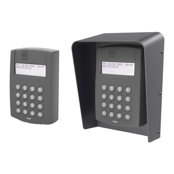
PINs and/or 13.56 MHz MIFARE® Ultralight/Classic and EM125kHz (UNIQUE) proximity cards. The terminal is mainly used for Time&Attendance applications. The device is offered in two versions: MCT68ME-IO-I for indoor installation and MCT68ME-IO-O with ME-7 metal enclosure for outdoor installation. The terminal is connected to access controller through RS485 interface. - Page 3 MCT68ME Operating Manual 09.07.2020 Fig. 1 MCT supply from MC16 access controller Fig. 2 MCT supply from dedicated power supply unit RS485 bus The communication method with MC16 access controller is provided with RS485 bus which can encompass up to 16 devices of RACS 5 system, each with unique address in range of 100-115. The bus topology can be freely arranged as star, tree or any combination of them except for loop.
- Page 4 MCT68ME Operating Manual 09.07.2020 Display The terminal is equipped with alphanumeric display (4 lines, 20 characters each). The display can be configured in regard of displayed information within high level configuration by means of Display command in VISO software navigation tree which is explained in AN011 application note. Keypad The terminal is equipped with numeric keypad and backlight.
-
Page 5: Installation
PINs The technical characteristics of the device are guaranteed for RFID cards supplied by Roger. Cards from other sources may be used, but they are not covered by the manufactures warranty. Before deciding to use specific Roger products with third-party contactless cards, it is recommended to conduct tests that will confirm satisfactory operation with the specific Roger device and software in which it operates. - Page 6 MCT68ME Operating Manual 09.07.2020 IN3 input line RS485 A RS485 bus, line A RS485 B RS485 bus, line B Not used Not used Tamper contact Tamper contact IO1 output line IO2 output line REL1-NC REL1 relay normally closed contact REL1-COM REL1 relay common contact REL1-NO REL1 relay normally opened contact...
- Page 7 MCT68ME Operating Manual 09.07.2020 Fig. 5 MCT68ME-IO-I installation 7/15...
- Page 8 MCT68ME Operating Manual 09.07.2020 Fig. 6 MCT68ME-IO-O installation 8/15...
-
Page 9: Operation Scenarios
MCT68ME Operating Manual 09.07.2020 Installation guidelines The terminal should be mounted on a vertical structure (wall) away from sources of heat and moisture. Front panel should be attached in such way as the tamper detector (fig. 4) would firmly press the back panel. -
Page 10: Low Level Configuration (Rogervdm)
MCT68ME Operating Manual 09.07.2020 Fig. 8 Typical connection diagram for the –IO version terminal and MC16 access controller 4. C ONFIGURATION Low level configuration (RogerVDM) The purpose of low level configuration is to prepare device for operation in RACS 5 system. Programming procedure with RogerVDM software: 1. - Page 11 MCT68ME Operating Manual 09.07.2020 Fig. 9 Connection to RUD-1 interface (low level configuration) Table 4. List of low level parameters Communication settings RS485 address Parameter defines device address on RS485 bus. Range: 100-115. Default value: 100. RS485 communication timeout [s] Parameter defines delay after which device will signal lost communication with controller.
- Page 12 MCT68ME Operating Manual 09.07.2020 then it cannot be sent to controller when concluded with [#] key. When set to 0 then PINs are disabled. Range: 4-8. Default value: 4. Max. length of PIN Parameter defines the maximal number of digits for PIN entered with keypad.
-
Page 13: Firmware Update
The purpose of high level configuration is to define logical functioning of the terminal which communicates with the MC16 access controller and it depends on applied scenario of operation. The example of access control system configuration is given in AN006 application note which is available at www.roger.pl. 5. F IRMWARE UPDATE The update requires connection of reader to computer with RUD-1 interface (fig. -
Page 14: Ordering Information
1200m maximal cable length for RS485 bus between controller and reader IP Code MCT68ME-IO-I: IP41 MCT68ME-IO-O: IP54 MCT68ME-IO-I: Class I, indoor general conditions, temperature: +5°C to Environmental class +40°C, relative humidity: 10 to 95% (no condensation) (according 50133-1) MCT68ME-IO-O: Class IV, outdoor general conditions, temperature: -25°C to +60°C, relative humidity: 10 to 95% (no condensation) - Page 15 Weight of the equipment is specified in the document. Contact: Roger sp. z o.o. sp.k. 82-400 Sztum Gościszewo 59 Tel.: +48 55 272 0132 Fax: +48 55 272 0133 Tech.
Need help?
Do you have a question about the MCT68ME-IO-I and is the answer not in the manual?
Questions and answers