
Related Manuals for Roger MC16


Summary of Contents for Roger MC16
- Page 1 Roger Access Control System MC16 access controller Installation manual Product version: 1.1 Firmware version: 1.1.4 or newer Document version: Rev. E...
-
Page 2: Software License
VISO software level by right clicking the controller and then clicking Select Controller License File command. Note: Memory card is integral part of MC16 electronic module. If the card is lost or damaged then the controller may interrupt collection of events and stop normal operation. -
Page 3: Low Level Configuration
EVEL ONFIGURATION Low level configuration is necessary to set MC16’s board parameters and must be performed before MC16 controller is enrolled into RACS 5 system. During first low level configuration own IP address and communication key are configured. Programming of other parameters depends on the individual installation scenario requirements and is not obligatory. -
Page 4: Memory Reset
MC16 Installation Manual.doc 2018-11-22 Note: Whenever the low level configuration of the MC16 controller is changed, it is necessary to detect the controller in VISO software and upload the high level configuration. EMORY ESET Memory Reset procedure erases all low level configuration settings including communication key (none) and default IP address of the controller (192.168.0.213). - Page 5 Fig. 2 MC16 supply from 12/24VDC. RS485 B Every module or device connected to the MC16 RS485 bus must have the unique address set in 100-115 range. All power supply sources used to supply modules and devices connected to the same RS485 bus, must be connected by dedicated (separate) wire of any diameter and optionally, grounded in any arbitrary selected point.
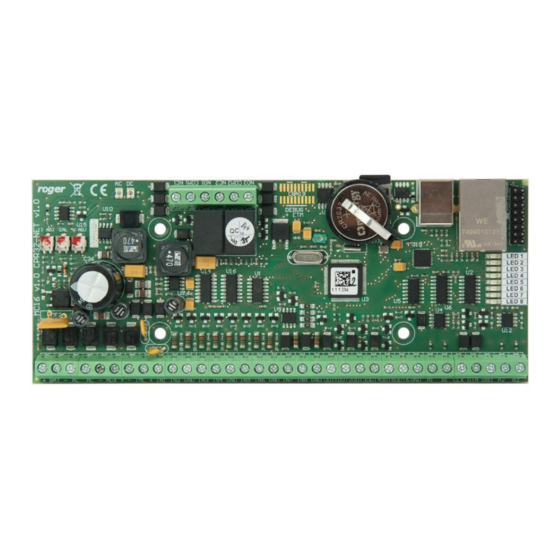
- Page 6 MC16 Installation Manual.doc 2018-11-22 MC16 E LECTRONIC ODULE Fig. 3 MC16 board view. Table 1: MC16 Connection Terminals Terminal Description Terminal Description REL1/ NC contact IN5 input COM1 REL1/ COMM contact IN6 input REL1/NO contact Signal ground REL2/NO contact IN7 input...
- Page 7 MC16 Installation Manual.doc 2018-11-22 12V DC output available Table 3: Status LEDs Function in normal mode Function in service mode LED1 Normal mode None LED2 None Service mode LED3 Blinking: Low level configuration error not used ON: High level configuration error...
-
Page 8: Installation
MC16 Installation Manual.doc 2018-11-22 NSTALLATION IAGRAMS Fig. 4 Connecting Wiegand readers to MC16 board. 8/14... - Page 9 MC16 Installation Manual.doc 2018-11-22 Fig. 5 Connection of RS485 devices and modules to MC16 board. 9/14...
- Page 10 MC16 Installation Manual.doc 2018-11-22 Fig. 6 Input topologies. 10/14...
- Page 11 MC16 Installation Manual.doc 2018-11-22 Fig. 7 Common supply minus wire connections. 11/14...
- Page 12 MC16 Installation Manual.doc 2018-11-22 Fig. 8 Example of the access system with RS485 modules and devices. 12/14...
- Page 13 MC16 Installation Manual.doc 2018-11-22 Fig. 9 Access system with two read-in/out doors supplied from MC16 built-in power supply. 13/14...
- Page 14 Weight of the equipment is specified in the document. Contact: Roger sp. z o.o. sp.k. 82-400 Sztum Gościszewo 59 Tel.: +48 55 272 0132 Fax: +48 55 272 0133 Tech.
Need help?
Do you have a question about the MC16 and is the answer not in the manual?
Questions and answers