Roger MCT88M-IO Operating Manual
Access control system
Hide thumbs
Also See for MCT88M-IO:
- Operating manual (21 pages) ,
- Installation manual (2 pages) ,
- Installation manual (2 pages)

Related Manuals for Roger MCT88M-IO


Summary of Contents for Roger MCT88M-IO
- Page 1 Roger Access Control System MCT88M-IO Operating Manual Product version: 1.0 Firmware version: 1.0.2.97 or newer Document version: Rev. A...
-
Page 2: Design And Application
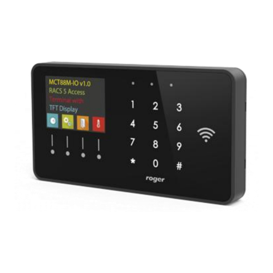
1. D ESIGN AND APPLICATION The MCT88M-IO is an access terminal dedicated to RACS 5 system. The terminal is equipped with colour graphic display, sensor type keypad, 4 function keys and MIFARE Ultralight/Classic/DESFire/Plus/ reader. Users can identify at the terminal with PINs, MIFARE cards and mobile devices equipped with NFC (Near Field Communication) or BLE (Bluetooth Low Energy) technology. - Page 3 MCT88M-IO Operating Manual.doc 2019-03-06 Fig. 1 MCT88M-IO supply from dedicated power supply unit Fig. 2 MCT88M-IO supply from MC16 access controller RS485 bus The primary communication method with MC16 access controller is provided with RS485 bus which can encompass up to 16 devices of RACS 5 system, each with unique address in range of 100-115. The bus topology can be freely arranged as star, tree or any combination of them except for loop.
-
Page 4: Ethernet Interface
2019-03-06 Ethernet interface MCT88M-IO terminal can communicate with MC16 controller via LAN if MCX16-RS expander is connected as intermediary device (fig. 3). In such scenario, MC16 controller and MCX16-RS can be connected to the same network but they communicate solely via RS485 bus. -
Page 5: Led Indicators
MCT88M-IO Operating Manual.doc 2019-03-06 Fig. 4 LED indicators and function keys LED indicators The terminal is equipped with three LED indicators (fig. 4) which are used to signal integral functions and they can be additionally programmed with other available functions within high level configuration (VISO). - Page 6 MCT88M-IO Operating Manual.doc 2019-03-06 NO type NO input can be in normal or in triggered state. In normal state C contacts are opened. Input triggering is caused by C contacts closing. Fig. 5 NO input type NC type NC input can be in normal or in triggered state. In normal state C contacts are closed.
- Page 7 MCT88M-IO Operating Manual.doc 2019-03-06 2EOL/NO type 2EOL/NO input can be in normal, triggered, tamper (sabotage) or malfunction state. In normal state C contacts are opened, while contacts are closed. Input triggering is caused by C Tamp contacts closing. C contacts opening is recognized as the Tamp tamper (sabotage) state.
-
Page 8: 3Eol/Dw/No And 3Eol/Dw/Nc
Built-in tamper (sabotage) detector enables detection of unauthorized opening of device’s enclosure as well as detachment of the enclosure from wall. The detector is internally connected to the MCT88M-IO fourth input. It does not require low level configuration (RogerVDM) or any additional installation arrangements but it is essential to mount the terminal in such way that tamper lever (fig.16) would properly press the detector... -
Page 9: Mifare Cards
Bluetooth additionally verify if the parameter BLE activated is enabled. Install Roger Mobile Key (RMK) app on mobile device and configure the same parameters as in the terminal. Create key (authentication factor) in RMK defining its type and number, then create the same authentication factor in VISO software (fig. -
Page 10: Installation
MCT88M-IO Operating Manual.doc 2019-03-06 2. I NSTALLATION Fig. 14 Enclosure disassembly Fig. 15 Internal side of the front panel Table 3. Screw terminals Screw terminal Description OUT2 OUT2 output line OUT1 OUT1 output line IN3 input line IN2 input line... -
Page 11: Operation Scenarios
PERATION SCENARIOS Access, T&A and building automation terminal The MCT88M-IO terminal when connected to MC16 access controller can be at the same time used for access control, Time&Attendance and building automation functionalities. The example of connection diagram for such scenario is shown in fig. 17 where the terminal’s power supply line and RS485 bus are connected directly to the controller and relay outputs of MCX8 expander are used to control building automation. -
Page 12: Vending Terminal (Pos)
Fig. 17 Typical connection diagram for the terminal and MC16 access controller Vending terminal (PoS) The MCT88M-IO terminal when connected to virtual controller via Ethernet (LAN) can be used as Point of Sale terminal. Virtual controller is a Windows Service installed on computer by means of RogerSVC software which is available at www.roger.pl. -
Page 13: Low Level Configuration (Rogervdm)
MCT88M-IO Operating Manual.doc 2019-03-06 4. C ONFIGURATION Low level configuration (RogerVDM) The purpose of low level configuration is to prepare device for operation in RACS 5 system. In order to start the configuration, connect the terminal to RUD-1 interface (fig. 18) and start RogerVDM software. - Page 14 BLE authentication factor class Parameter defines acceptable type of keys (authentication factors) created in Roger Mobile Key app for Bluetooth (BLE) communication. UCE means lower security and quicker identification while REK means higher security and slower identification. It is necessary to apply classes in RMK which are acceptable for terminal.
- Page 15 MCT88M-IO Operating Manual.doc 2019-03-06 controller. Range: [0]: No, [1]: Yes. Default value: [0]: Yes. PIN followed by [#] key Parameter enables use of PINs with variable length. In such scenario PIN is concluded with [#] key. Range: [0]: No, [1]: Yes. Default value: [0]: Yes.
- Page 16 MCT88M-IO Operating Manual.doc 2019-03-06 Tamper, Alarm A, Alarm B [Ohm] Parameter defines resistor for parametric (EOL) inputs. Output polarity OUT1, OUT2, REL1 Parameter defines polarity of output. Normal polarity means that the output by default is switched off while Reversed polarity means that the output by default is switched on.
- Page 17 0-31 and 0-14 for sectors 32-39. Default value: 0. Key type Parameter defines key type used to access sector with PCN. Range: [0]: A, [1]: B, [2]: Roger. Default value: [0]: A. Parameter defines 6 bytes (12 HEX digits) key for accessing sector where PCN is stored.
-
Page 18: Manual Addressing
The purpose of high level configuration is to define logical functioning of the terminal which communicates with the MC16 access controller and it depends on applied scenario of operation. The example of access control system configuration is given in AN006 application notes which is available at www.roger.pl. 5. F IRMWARE UPDATE New firmware can be uploaded to the terminal by means of included memory card. -
Page 19: Specification
I/Os; RS485; Ethernet. MCX8-BRD I/O expander; 8 supervised inputs; 8 relay outputs 1.5 A/30 V; 13.8 VDC supply input. RUD-1 Portable USB-RS485 communication interface dedicated to ROGER access control devices. 8. P RODUCT HISTORY Table 7. Product history Version... - Page 20 Weight of the equipment is specified in the document. Contact: Roger sp. z o.o. sp.k. 82-400 Sztum Gościszewo 59 Tel.: +48 55 272 0132 Fax: +48 55 272 0133 Tech.
Need help?
Do you have a question about the MCT88M-IO and is the answer not in the manual?
Questions and answers