Roger EDGE1 Instruction And Warnings For The Installer
Hide thumbs
Also See for EDGE1:
- Instruction and warnings for the installer (256 pages) ,
- Instruction and warnings for the installer (42 pages) ,
- Instruction and warnings for the installer (304 pages)
Table of Contents

Related Manuals for Roger EDGE1


Summary of Contents for Roger EDGE1
- Page 1 P4.20 IS160 Rev.12 18/02/2021 EDGE1 centrale di comando per cancelli battenti Istruzioni originali IT - Istruzioni ed avvertenze per l’installatore EN - Instructions and warnings for the installer...
-
Page 3: Table Of Contents
INDICE • INDEX • INDEX • INDEXER • ÍNDICE • ÍNDICE • INDEX • INDEKS ITALIANO Avvertenze generali Dichiarazione di Conformità Simbologia Descrizione prodotto Aggiornamenti versione P4.20 Caratteristiche tecniche prodotto Descrizione dei collegamenti Installazione tipo Collegamenti elettrici Comandi e accessori Tasti funzione e display Accensione o messa in servizio 10 Modalità... - Page 5 Illustrazioni e schemi - Pictures and schemes - Bilder und Pläne Illustrations et schémas - Ilustraciones y esquemas - Ilustrações e esquemas P4.20 Display a 4 cifre e 6 tasti di programmazione 4 digit display and 6 programming Fusibile 3A Fusibile 4A buttons Fuse 3A...
- Page 6 PRIMARIO FUSIBILE FUSE SECONDARIO Blu/Blue Blu/Blue Blu/Blue Blu/Blue Nero/Black Nero/Black Nero/Black Nero/Black 230 Vac 230 Vac 230 Vac F2 F2 F3 F3 or or FUSIBILE FUSIBILE FUSIBILE FUSIBILE FUSIBILE FUSIBILE 115 Va 115 Vac 115 Vac FUSE FUSE FUSE FUSE FUSE FUSE SEC2...
- Page 7 Apertura parziale / Par al opening Passo passo / Step by step Chiusura / Closing Apertura / Opening Orologio (N.A.) / Timer (N.O.) RG58 max 10 m Antenna STOP COS1 Bordo sensibile 1 / Safety edge 1 COS2 Bordo sensibile 2 / Safety edge 2 24 Vdc 3W Spia cancello aperto / Open gate light +24V...
- Page 8 COLLEGAMENTO CON 1 COPPIA FOTOCELLULE SINCRONIZZATE (MODALITÁ NORMALE, SOLO COPPIA MASTER) CONNECTION WITH 1 SYNCHRONISED PHOTOCELL PAIR (NORMAL MODE, MASTER PAIR ONLY) ROSSO = libero da jumper RED = jumper free JUMPER DI SINCRONIZZAZIONE (PER MASTER) SYNCHRONISATION JUMPER (FOR MASTER) 1 2 3 1 2 3 COS1...
- Page 9 COLLEGAMENTO CON 2 COPPIE FOTOCELLULE SINCRONIZZATE (MODALITÁ NORMALE, 1 MASTER E 1 SLAVE) CONNECTION WITH 2 SYNCHRONISED PHOTOCELL PAIRS (NORMAL MODE, 1 MASTER AND 1 SLAVE) ROSSO = libero da jumper RED = jumper free JUMPER DI SINCRONIZZAZIONE (PER MASTER) SYNCHRONISATION JUMPER (FOR MASTER) 1 2 3...
- Page 10 TEST FOTOCELLULE · PHOTOCELLS TEST ( COLLEGAMENTO CON 1 COPPIA FOTOCELLULE SINCRONIZZATE (MODALITÁ NORMALE, SOLO COPPIA MASTER) CONNECTION WITH 1 SYNCHRONISED PHOTOCELL PAIR (NORMAL MODE, MASTER PAIR ONLY) ROSSO = libero da jumper RED = jumper free JUMPER DI SINCRONIZZAZIONE (PER MASTER) SYNCHRONISATION JUMPER (FOR MASTER)
- Page 11 TEST FOTOCELLULE · PHOTOCELLS TEST ( COLLEGAMENTO CON 2 COPPIE FOTOCELLULE SINCRONIZZATE (MODALITÁ NORMALE, 1 MASTER E 1 SLAVE) CONNECTION WITH 2 SYNCHRONISED PHOTOCELL PAIRS (NORMAL MODE, 1 MASTER AND 1 SLAVE) ROSSO = libero da jumper RED = jumper free JUMPER DI SINCRONIZZAZIONE (PER MASTER) SYNCHRONISATION JUMPER...
- Page 12 BATTERY SAVING ( BATTERY SAVING + TEST FOTOCELLULE · PHOTOCELLS TEST ( COLLEGAMENTO CON 1 COPPIA FOTOCELLULE SINCRONIZZATE (MODALITÁ NORMALE, SOLO COPPIA MASTER) CONNECTION WITH 1 SYNCHRONISED PHOTOCELL PAIR (NORMAL MODE, MASTER PAIR ONLY) ROSSO = libero da jumper RED = jumper free JUMPER DI SINCRONIZZAZIONE (PER MASTER) SYNCHRONISATION JUMPER...
- Page 13 BATTERY SAVING ( BATTERY SAVING + TEST FOTOCELLULE · PHOTOCELLS TEST ( COLLEGAMENTO CON 2 COPPIE FOTOCELLULE SINCRONIZZATE (MODALITÁ NORMALE, 1 MASTER E 1 SLAVE) CONNECTION WITH 2 SYNCHRONISED PHOTOCELL PAIRS (NORMAL MODE, 1 MASTER AND 1 SLAVE) ROSSO = libero da jumper RED = jumper free JUMPER DI SINCRONIZZAZIONE (PER MASTER)
- Page 14 PRIMARIO SECONDARIO SEC2 SEC1 PROG TEST TRANSFORMER B71/BCHP B71/BCHP B71/BCHP CARICA BATTERIE CARICA BATTERIE CARICA BATTERIE BATTERY CHARGER BATTERY CHARGER BATTERY CHARGER COS1 COS2 +24V +LAM BATTERY BATTERY BLACK FUSE T10A max. 3m BLACK 5x20 2 x 12V 4500mAh AGM Ba ery ONLY...
- Page 15 SMARTY/EMA Marrone/Brown Blu/Blue Nero/Black SMARTY/EMA MOTORE MOTOR Marrone/Brown Blu/Blue Nero/Black SMARTY Marrone/Brown MOTORE Blu/Blue MOTOR Nero/Black...
-
Page 16: Avvertenze Generali
La mancata osservanza delle informazioni contenute nel presente manuale può dare luogo a infortuni personali o danni all’apparecchio. ROGER TECHNOLOGY declina qualsiasi responsabilità derivante da un uso L’installazione, i collegamenti elettrici e le regolazioni devono essere effettuati da norme vigenti. - Page 17 EN 12453 e EN 12445. ROGER TECHNOLOGY declina ogni responsabilità qualora vengano installati In caso sia attiva la funzione uomo presente dovrà essere cura dell’installatore deformabile in gomma, la velocità di chiusura del varco ed in generale tutti gli e il funzionamento dell’automazione e che il tipo di comando ed il tipo di utilizzo...
-
Page 18: Dichiarazione Di Conformità
Smaltire e riciclare gli elementi dell’imballo secondo le disposizioni delle norme vigenti. nell’uso dell’impianto. Dichiarazione CE di Conformità CHIARA che la centrale di comando EDGE1... -
Page 19: Simbologia
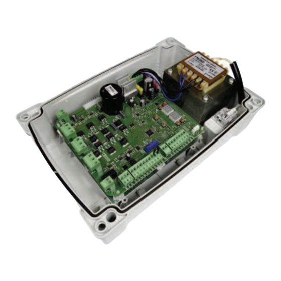
22. Descrizione prodotto La centrale EDGE1 a 36V controlla in modalità sensorless 1 o 2 motori ROGER brushless per applicazioni su ante di grandi dimensioni o di peso elevato. Attenzione all’impostazione del parametro A1. Una errata impostazione può causare anomalie nel funzionamento dell’automazione. -
Page 20: Aggiornamenti Versione P4.20
La somma degli assorbimenti di tutti gli accessori collegati non deve superare i dati di potenza massima indicati in tabella. I dati sono garantiti SOLO con accessori originali ROGER TECHNOLOGY. L'utilizzo di accessori non originali può causare malfunzionamenti. ROGER TECHNOLOGY declina ogni responsabilità per installazioni errate o non conformi. -
Page 21: Descrizione Dei Collegamenti
Descrizione dei collegamenti Installazione tipo loro caratteristiche tecniche. Cavo consigliato Alimentazione di rete Motore 1 Cavo 3x2,5 mm² (max 10 3x4 mm² (max 30 m) Motore 2 Cavo 3x2,5 mm² (max 10 3x4 mm² (max 30 m) F4ES/F4S Cavo 5x0,5 mm (massimo 20 m) F4ES/F4S Cavo 3x0,5 mm... -
Page 22: Collegamenti Elettrici
(marrone) e N (blu), presenti all’interno dell’automazione. bloccarlo mediante l’apposito fermacavi. TRANSFORMER Per il perfetto funzionamento delle automazioni Brushless la tensione di ±10% per centrale EDGE1 220÷230 -COM I collegamenti alla rete di distribuzione elettrica e ad eventuali altri conduttori a bassa... -
Page 23: Comandi E Accessori
Comandi e accessori Le sicurezze con contatto N.C., se non installate devono essere ponticellate ai morsetti COM, oppure disabilitate modificando i parametri N.A. (Normalmente Aperto) N.C. (Normalmente Chiuso) CONTATTO DESCRIZIONE 13(COR) 13(COR) • • 16(+LAM) 15(COM) É possibile selezionare le impostazioni di prelampeggio dal parametro e le modalità... - Page 24 CONTATTO DESCRIZIONE 27(ST) 26(COM) Ingresso comando di STOP (N.C. oppure 8.2 kOhm). L’apertura del contatto di sicurezza provoca l’arresto del movimento. NOTA – . Contatto in ingresso N.C. (normalmente chiuso). 29 (ANT) 30 Collegamento antenna per ricevitore radio ad innesto. NOTA 32(ORO 31(COM) Ingresso contatto temporizzato orologio (N.A.).
-
Page 25: Tasti Funzione E Display
Tasti funzione e display TASTO DESCRIZIONE Parametro successivo DOWN Parametro precedente Incremento di 1 del valore del parametro DOWN Decremento di 1 del valore del parametro PROG Apprendimento della corsa PROG TEST TEST Attivazione modalità TEST • Premere i tasti UP •... -
Page 26: Modalità Visualizzazione Di Stato Comandi E Sicurezze26
10.2 Modalità visualizzazione di stato comandi e sicurezze STATO DEI COMANDI STATO DELLE SICUREZZE STATO DEI COMANDI: Le indicazioni dei comandi (segmenti AP=apre, parziale, ORO=orologio) sono normalmente spente. COS1 accende il segmento PP). STATO DELLE SICUREZZE: COS2 POWER STOP che sono in allarme o non collegate. 10.3 Modalità... -
Page 27: Apprendimento Della Corsa
Apprendimento della corsa 11.1 Prima di procedere 1. Selezionare il modello dell’automazione installata con il parametro Motore HIGH SPEED Motore REVERSIBILE TIPO SELEZIONE MODELLO CONFIGURAZIONI MOTORE BE20/200/HS Serie BR20 BH23/282 Serie BR21 SMARTY5 Se installato SMARTY/EMA impostare NOTA , il display visualizza il messaggio di richiesta dati di posizione . - Page 28 BE20/400 MONOS4 BR20/400/R Attenzione: I motori della serie SMARTY con SMARTY/EMA installato non devono essere installati per aprire l'anta 2. Selezionare il numero di motori installati con il parametro OPEN CLOSE 4. Prevedere le battute meccaniche di arresto sia in apertura che in chiusura. 5.
-
Page 29: Procedura Di Apprendimento
11.2 Procedura di apprendimento PROG PROG AP P- AU to 1 click x4 s TEMPO DI MOTORE 1 RITARDO MOTORE 2 APERTO APERTURA PARAM. 25 APERTURA Sì x2 s AU to AU to TEMPO DI MOTORE 2 RITARDO MOTORE 1 CHIUSO CHIUSURA PARAM. -
Page 30: Indice Dei Parametri
Indice dei parametri VALORE DI PARAM. DESCRIZIONE PAGINA FABBRICA VEDI CAP.11 Selezione modello automazione Richiusura automatica dopo il tempo di pausa (da cancello completamente aperto) Prelampeggio Funzione condominiale sul comando di apertura parziale (PED) Abilitazione funzione a uomo presente Regolazione del rallentamento MOTORE 1 in apertura (visibile se Regolazione del rallentamento MOTORE 2 in apertura (visibile se Regolazione del rallentamento MOTORE 1 in apertura e chiusura Regolazione del rallentamento MOTORE 1 in chiusura (se... - Page 31 VALORE DI PARAM. DESCRIZIONE PAGINA FABBRICA Regolazione accelerazione alla partenza in apertura e chiusura MOTORE 1 Regolazione accelerazione alla partenza in apertura e chiusura MOTORE 2 Abilitazione del colpo di sblocco (colpo d'ariete) Regolazione della velocità in apertura Regolazione della velocità in chiusura Regolazione dello spazio di accostamento del MOTORE 1 in APERTURA (solo Regolazione dello spazio di accostamento del MOTORE 2 in APERTURA (solo Regolazione dello spazio di accostamento del MOTORE 1 in CHIUSURA (solo...
- Page 32 VALORE DI PARAM. DESCRIZIONE PAGINA FABBRICA Selezione delle limitazioni nel funzionamento a batteria Selezione del tipo di batteria e riduzione dei consumi Selezione gestione funzionamento a batteria Abilitazione attivazione manutenzione periodica Regolazione contatore delle ore di attivazione allarme manutenzione Ripristino ai valori standard di fabbrica Versione HW Anno di produzione Settima di produzione...
-
Page 33: Menù Parametri
Menù parametri VALORE DEL PARAMETRO PARAMETRO Selezione modello automazione ATTENZIONE! Una errata impostazione può causare anomalie nel funzionamento dell’automazione. NOTA BE20/200/HS IRREVERSIBILE HIGH SPEED. Serie BR20 IRREVERSIBILE. Serie BH23 IRREVERSIBILE. Serie BR21 IRREVERSIBILE. SMARTY 5 oppure SMARTY 7 IRREVERSIBILE. SMARTY 7R REVERSIBILE. - Page 34 Prelampeggio Disabilitato. Il lampeggiante si attiva durante la manovra di apertura e chiusura. Da 1 a 10 s di prelampeggio prima di ogni manovra. 5 s di prelampeggio prima della manovra in chiusura. Funzione condominiale sul comando di apertura parziale (PED) Abilitato.
- Page 35 Regolazione controllo posizione ANTA 1 completamente aperta/chiusa in apertura e chiusura. NOTA BR21, quando l'anta raggiunge la posizione di completa chiusura, regolare la battuta meccani Regolazione controllo posizione ANTA 2 completamente aperta/chiusa in apertura e chiusura. Attenzione! NOTA BR21, quando l'anta raggiunge la posizione di completa chiusura, regolare la battuta meccani Regolazione apertura parziale (%) NOTA dal 15% al 99% della corsa totale...
- Page 36 Regolazione tempo di ritardo (sfasamento) in apertura del MOTORE 2 In apertura il MOTORE 2 parte con un ritardo regolabile rispetto al MOTORE 1. da 0 a 10 s. Regolazione tempo di ritardo (sfasamento) in chiusura del MOTORE 1 In chiusura il MOTORE 1 parte con un ritardo regolabile rispetto al MOTORE 2. da 0 a 30 s.
- Page 37 Regolazione coppia MOTORE 2 Aumentando o diminuendo i valori del parametro, si aumenta o si diminuisce la coppia del motore, e di conseguenza si regola la sensibilità di intervento sugli ostacoli. Si raccomanda di utilizzare valori inferiori a SOLO per installazioni particolarmente leggere e che non siano sottopo ste ad eventi atmosferici sfavorevoli (vento forte o temperature rigide).
- Page 38 chiudere. INVERSIONE RITARDATA. Con fotocellula oscurata il cancello si ferma. Liberata la fotocellula il cancello apre. Modalità di funzionamento della fotocellula FT1 con cancello chiuso NOTA La fotocellula oscurata invia il comando di apertura del cancello. Impostazione modalità di funzionamento della fotocellula FT2 in apertura INVERSIONE IMMEDIATA.
- Page 39 Selezione del tipo di test fotocellule sull'ingresso FT2 Test fotocellule disabilitato. Test fotocellule abilitato SOLO in apertura. Test fotocellule abilitato SOLO in chiusura. Test fotocellule abilitato in apertura e chiusura. Gestione e modalità della reversibilità automazione SMARTY 5R5-SMARTY 7R . NOTA di sblocco.
- Page 40 PASSO PASSO. APERTURA PARZIALE. APERTURA. CHIUSURA. STOP. parametro viene ignorato. viene ignorato. PASSO PASSO con conferma di sicurezza APERTURA PARZIALE con conferma di sicurezza APERTURA con conferma di sicurezza CHIUSURA con conferma di sicurezza Per evitare che la pressione involontaria di un tasto del radiocomando attivi erroneamente il cancello, viene richiesta una conferma di •...
- Page 41 Regolazione tempo di attivazione della chiusura/apertura garantita NOTA: Da 2 a 90 s di attesa. Da 2 a 9 min di attesa. Selezione delle limitazioni nel funzionamento a batteria NOTA: diverso da segnalazione mediante uscita COR (se parametri opportunamente impostati). Quando la tensione di batteria scende alla soglia selezionata con par.
- Page 42 Ripristino ai valori standard di fabbrica NOTA. x4 s Attenzione! Il ripristino cancella ogni selezione fatta in precedenza tranne il parametro i parametri siano adeguati all’installazione. • Togliere alimentazione. • • Dopo 4 s il display lampeggia • I valori standard di fabbrica sono stati ripristinati. NOTA Versione HW Anno di produzione...
- Page 43 Procedura di attivazione password: • Inserire i valori desiderati nei parametri visualizzare il parametro • Con i tasti UP • Premere per 4 s i tasti + e -. • • Procedura sblocco temporaneo: • Inserire la password. • Procedura di cancellazione password: •...
-
Page 44: Segnalazione Degli Ingressi Di Sicurezza E Dei Comandi (Modalità Test)
Segnalazione degli ingressi di sicurezza e dei comandi (modalità TEST) DISPLAY POSSIBILE CAUSA INTERVENTO DA SOFTWARE INTERVENTO TRADIZIONALE Contatto STOP di sicurezza aperto. Installare un pulsante di STOP (N.C.) oppu Errata selezione del parametro parametro re ponticellare il contatto ST con il contatto COM. -
Page 45: Segnalazione Allarmi E Anomalie
Segnalazione allarmi e anomalie SEGNALAZIONE PROBLEMA POSSIBILE CAUSA INTERVENTO ALLARME LED POWER spento Manca alimentazione. LED POWER spento Fusibili bruciati. Sostituire il fusibile. Si raccomanda di estrarre e reinserire il fusibile sola mente in assenza di tensione di rete. Anomalia nella tensione di ali Togliere alimentazione, attendere 10 s e ridare alimen mentazione di ingresso. - Page 46 SEGNALAZIONE PROBLEMA POSSIBILE CAUSA INTERVENTO ALLARME Errata installazione dei motori. lato non devono essere installati per aprire l'anta verso Errato rilevamento posizione MO e ripetere la TORE 2 rispetto alla lunghezza procedura di apprendimento. della corsa. Se il problema persiste si consiglia di sostituire l'en coder.
-
Page 47: Modalità Info
PER USCIRE 1 click DALLA MODALITA’ x5 s La Modalità INFO permette di visualizzare alcuni valori misurati dalla centrale EDGE1. Dalla modalità “Visualizzazione comandi e sicurezze” e con motori fermi, premere per 5 s il tasto TEST. Parametro Funzione rispetto alla lunghezza totale. -
Page 48: Sblocco Meccanico
; il Esempio: 1-PREMERE 2-RILASCIARE 3-RI-PREMERE APRE CHIUDE APRE CHIUDE APRE CHIUDE oppure oppure oppure oppure entro 1 s • Il MOTORE in oggetto si attiva in apertura premendo il tasto "FRECCIA SU", si attiva in chiusura premendo il tasto "FRECCIA GIÙ". -
Page 49: Modalità Di Recupero Posizione Con Encoder Assoluto (Solo Serie Smarty)
Modalità di recupero posizione CON encoder assoluto (solo serie SMARTY) Dopo una interruzione di tensione o lo sblocco del cancello, al primo comando ricevuto la centrale recupera immediatamente la posizione delle ante, grazie all'encoder assoluto. Nel caso la centrale rilevasse una posizione errata delle ante, correggerà automaticamente l'errore. Esempio Attenzione! le ante. -
Page 50: Smaltimento
Informazioni aggiuntive e contatti Tutti i diritti relativi alla presente pubblicazione sono di proprietà esclusiva di ROGER TECHNOLOGY. comportino un cambio di versione FW. In assenza di revisione del manuale di istruzioni, si intende che queste istruzioni valgono per questa e successive versioni FW della centrale di comando. -
Page 51: General Safety Precautions
ROGER TECHNOLOGY is not liable for failure to observe the good practices in during use. The safety devices (photocells, sensing edges, emergency stops, etc.) must be in force, the good practices criteria, the installation environment, the operating logic of the system and the forces generated by the motorised door or gate. - Page 52 The installer is required to measure impact forces and select on the control unit the appropriate speed and torque values to ensure that the door or gate ROGER TECHNOLOGY cannot be held responsible for any damage or injury caused by the installation of incompatible components which compromise the safety and correct operation of the device.
-
Page 53: Declaration Of Conformity
These instructions must be kept and must be made available to any other persons authorised to use the installation. Declaration CE of Conformity The undersigned Dino Florian, legal representative of Roger Technology - Via Botticelli 8, 31021 Mogliano V.to (TV) DECLARES that the EDGE1 | 17. -
Page 54: Symbols
22. Product description The 36 V EDGE1 control unit controls 1 or 2 ROGER brushless motors in sensorless mode for applications on large sized or heavy gate wings. Ensure that the parameter A1 is set correctly. If this parameter is not set correctly, the automation system may not function properly. -
Page 55: Updates Of Version P4.20
The total of the absorption values of all the accessories connected must not exceed the maximum power values shown in the table. The values are guaranteed with original ROGER TECHNOLOGY accessories ONLY. All the connections are protected by fuses (refer to the table). The courtesy light requires an external fuse. -
Page 56: Description Of Connections
Description of connections Typical installation It is the installer's responsibility to verify the adequacy of the cables in relation to the devices used in the installation and their technical characteristics. Recommended cable Power supply double insulated cable Motor 1 Cable 3x2,5 mm² (max 10 3x4 mm²... -
Page 57: Electrical Connections
The cables must be double insulated, strip them near the relevant connection terminals and lock them with clamps (not supplied). DESCRIPTION Mains power supply 230 Vac ±10% 50 Hz connection. (EDGE1/115/BOX 115 Vac ± 10% 60Hz). Fuse 5x20 T2A. Secondary transformer input for 26 V AC motor power (SEC1) and for 19 V power to logical control and peripheral devices (SEC2). -
Page 58: Commands And Accessories
Commands and Accessories If not installed, safety devices with NC contacts must be jumpered at the COM terminals, or disabled by modifying the parameters N.C. (Normally Closed). CONTACT DESCRIPTION 13 (COR) Output (potential free contact) for connecting courtesy light. 13 (COR) •... - Page 59 27(ST) STOP command input (N.C. or 8.2 kOhm). 26(COM) The current manoeuvre is arrested if the safety contact opens. N.B.: the controller is supplied with this contact already jumpered by ROGER TECHNOLOGY. – . (normally closed) incoming contact. 29 (ANT) N.B.
-
Page 60: Function Buttons And Display
Function buttons and display BUTTON DESCRIPTION Next parameter DOWN Previous parameter Increase value of parameter by 1 DOWN Decrease value of parameter by 1 PROG Programme travel PROG TEST TEST Activate TEST mode • Press the UP buttons to view the parameter you intend to modify. •... -
Page 61: Command And Safety Device Status Display Mode
10.2 Command and safety device status display mode COMMAND STATUS SAFETY DEVICE STATUS COMMAND STATUS: The command status indicators on the display (segments AP = open, PP = step mode, CH = close, PED = partial opening, ORO= clock) are normally off. -
Page 62: Travel Acquisition
Travel acquisition For the system to function correctly, the gate travel must be acquired by the control. 11.1 Before starting 1. Select the automation system model installed with the parameter HIGH SPEED Motor REVERSIBLE Motor MOTOR SELECTION MODEL CONFIGURATIONS TYPE BE20/200/HS Serie BR20 BH23/282... - Page 63 BR20/400/R Attention: The motors of the SMARTY series with SMARTY/EMA installed must not be installed to open the door 2. Select the number of motors installed with the parameter . This parameter is set for two motors by default. 3. Check that the operator present function is not enabled ( OPEN CLOSE 4.
-
Page 64: Acquisition Procedure
11.2 Acquisition procedure: PROG PROG AP P- AU to x4 s 1 click PARAM. 25 MOTOR 1 DELAY MOTOR 2 OPEN OPENING TIME OPENING Sì x2 s AU to AU to PARAM. 26 MOTOR 2 DELAY MOTOR 1 CLOSED CLOSING TIME CLOSING •... -
Page 65: Index Of Parameters
Index of parameters FACTORY PARAM. DESCRIPTION PAGE DEFAULT Selecting automation system model CHAP. 11 Automatic closure after pause time (from gate completely open) Selecting step mode control function (PP) Condominium function for partial open command (PED) Enabling operator present function MOTOR 1 Setting deceleration during opening (visible if MOTOR 2 Setting deceleration during opening (visible if MOTOR 1 Setting deceleration during opening and closing... - Page 66 FACTORY PARAM. DESCRIPTION PAGE DEFAULT Setting start acceleration during opening and closing MOTOR 2 Enable lock release reverse impulse Speed opening setting Speed closing setting Opening approach distance setting MOTOR1 (only for SMARTY Series with motors) Opening approach distance setting MOTOR2 (only for SMARTY Series with motors) Closing approach distance setting MOTOR1 (only for SMARTY Series with motors)
- Page 67 FACTORY PARAM. DESCRIPTION PAGE DEFAULT Selecting limitations in battery operation Battery type selection and consumption reduction Selection of the battery operation management Enabling of regular maintenance activation Adjustment of regular maintenance activation hour counter Restoring factory default values HW version Year of manufacture Week of manufacture Serial number...
-
Page 68: Parameters Menu
Parameters menu PARAMETER PARAMETER VALUE Selecting automation system model WARNING! If this parameter is not set correctly, the automation system may not function properly. N.B.: in the event of a reset to restore the default parameters, this parameter must be set again manually. BE20/200/HS IRREVERSIBLE HIGH-SPEED piston. - Page 69 Flashing warning signal for 1 to 10 seconds prior to every manoeuvre. Condominium function for partial open command (PED) Enabled. Partial commands are ignored during gate opening. Enabling operator present function Disabled. Enabled. The open (AP) or close (CH) button must be pressed continuously to operate the gate. The gate stops when the button is released.
- Page 70 Adjusting LEAF 1 position control when completely opens or closes mechanical stop. The position of LEAF 1 is calculated by the system from the number of motor revolutions and the motor reduction gear ratio. Warning! Excessively low values cause the gate to reverse when it reaches the gate open stop. N.B.
- Page 71 Adjusting opening delay (alignment) of MOTOR 2 During opening, MOTOR 2 starts with an adjustable delay after MOTOR 1. From 0 to 10 s. Adjusting closing delay (alignment) of MOTOR 1 During closing, MOTOR 1 starts with an adjustable delay after MOTOR 2. From 0 to 30 s.
- Page 72 Setting motor torque MOTOR 2 Increasing or decreasing the value of the parameter increases or decreases motor torque and, as a result, adjusts obstacle detection sensitivity. Use values below SOLO ONLY for particularly lightweight installations not exposed to severe weather conditions (strong winds or very cold temperatures).
- Page 73 Photocell (FT1) mode with gate closed N.B.: this parameter is not visible if is set. If the photocell is obstructed, the gate cannot open. The gate opens when an open command is received, even if the photocell is obstructed. The photocell sends the gate open command when obstructed. Setting photocell mode during gate opening (FT2) DISABLED.
- Page 74 Photocell test disabled. Photocell test enabled on opening ONLY. Photocell test enabled on closure ONLY. Photocell test enabled on both opening and closure. Method and management of SMARTY 5R5- SMARTY 7R automation reversibility This parameter is visible ONLY if NOTE: Even though it is a REVERSIBLE unit, the motor is equipped with a lock release system. The SMARTY 5R5/7R motor is always REVERSIBLE.
- Page 75 STEP MODE. PARTIAL OPENING OPENING CLOSING. STOP. Courtesy light. The output COR is managed from the remote control. The light remains lit as long as the remote control is active. The parameter is ignored. The remote control turns the courtesy light on and off. The parameter is ignored.
- Page 76 Setting safeguarded closure/opening activation time N.B.: this parameter is not visible if the value of parameter Wait time settable from 2 to 90 s. Wait time settable from 2 to 9 min. Selecting limitations in battery operation N.B. is different than There is no limitation for the commands when the battery voltage drops under the selected threshold.
- Page 77 x4 s Warning! Restoring default settings cancels all settings made previously except for parameter that all parameters are suitable for the installation. • Turn off the power. • • The display flashes after 4 s • The default factory settings have now been restored. N.B.
- Page 78 Password activation procedure: • Enter the desired values for parameters buttons to view the parameter • Use the UP • Press and hold the • • Switch the control unit off and on again. Check that password protection is activated ( = Temporary unlock procedure: •...
-
Page 79: Safety Input And Command Status (Test Mode)
Safety input and command status (TEST mode) PHYSICAL CORRECTIVE AC- DISPLAY POSSIBLE CAUSE ACTION BY SOFTWARE TION The safety STOP contact is open. Check that parameter is set cor Install a STOP button (NC) or jumper Incorrect setting of parameter rectly the ST contact with the COM contact. -
Page 80: Alarms And Faults
Alarms and faults PROBLEM ALARM POSSIBLE CAUSE ACTION POWER LED off No power. Check power cable. POWER LED off Fuses blown. Replace fuse. Always disconnect from mains power before removing fuses. Input mains power voltage fault. Disconnect from mains power, wait Control initialisation failed. - Page 81 PROBLEM ALARM POSSIBLE CAUSE ACTION Incorrect installation of the motors Verify the correct installation of the motors. must not be installed to open the door towards Position detected of MOTOR 2 incon Check the setting of parameter and repeat gruent with travel length. the learning procedure.
- Page 82 THE INFO MODE x5 s INFO mode may be used to view certain parameters measured by the EDGE1 controller. Press and hold the TEST button for 5 seconds from the “View command signals and safety devices” mode with the motor stationary. The control unit displays the following parameters and the corresponding measured values in...
-
Page 83: Mechanical Release
the - button to return through the previous parameters. • In INFO mode, the automation system may be activated to test operation in real time. • The two motors may be controlled independently in OPERATOR PRESENT mode, ignoring the position data request message "... -
Page 84: Position Recovery With The Absolute Encoder (Smarty Range Only)
• stops the motors for 0.4 s. • the wings resume the manoeuvre at low speed through to the striker plate. • On the subsequent Step by Step command (PP), the wings carry out the manoeuvre at low speed again. 4. -
Page 85: Disposal
ROGER TECHNOLOGY is the exclusive proprietor holder of all rights regarding this publication. or any alterations to this document are prohibited without express prior authorised from by ROGER TECHNOLOGY. ROGER TECHNOLOGY reserves the right to modifying or perfecting the product, which will not imply a FW version change. - Page 86 ROGER TECHNOLOGY Via S. Botticelli 8 • 31021 Bonisiolo di Mogliano Veneto (TV) • ITALIA P.IVA 01612340263 • Tel. +39 041.5937023 • Fax. +39 041.5937024 www.rogertechnology.com...
Need help?
Do you have a question about the EDGE1 and is the answer not in the manual?
Questions and answers