Roger PR402DR Installation Manual
Hide thumbs
Also See for PR402DR:
- Installation manual (19 pages) ,
- Quick start manual (2 pages) ,
- Quick start manual (2 pages)
Table of Contents
Advertisement
Quick Links
Roger Access Control System
Installation guide for
PR402DR type access controllers
Firmware version: 1.18.6 or newer
Hardware version: 1.4
Document version: Rev. I
© 2016 ROGER sp. z o.o. sp.k. All rights reserved. This document is subject to the Terms of Use in their current version published at
the
www.roger.pl
website of the Roger sp. z o.o. sp.k. company (hereinafter referred to as ROGER).
Advertisement
Table of Contents

Related Manuals for Roger PR402DR


Summary of Contents for Roger PR402DR
- Page 1 Hardware version: 1.4 Document version: Rev. I © 2016 ROGER sp. z o.o. sp.k. All rights reserved. This document is subject to the Terms of Use in their current version published at www.roger.pl website of the Roger sp. z o.o. sp.k. company (hereinafter referred to as ROGER).
-
Page 2: Table Of Contents
3.2.1 PR402DR controller ....................... 9 3.2.2 PR402DR-BRD controller ....................9 3.3 Power supply ........................10 3.3.1 PR402DR and PR402DR-BRD controllers ............... 10 3.3.2 PR402DR-12VDC and PR402DR-12VDC-BRD controllers ..........12 3.4 Connection of door lock ....................13 3.5 Communication with controller ..................14 3.6 Communication of controller with peripheral devices ............ -
Page 3: Introduction
PR402DR and PR402DR-BRD versions are functionally identical but differ mechanically. PR402DR is installed inside plastic enclosure fitted to mounting on DIN 35 mm rail, while PR402DR-BRD is just a PCB module without enclosure. Both controllers replace discontinued PR402-BRD, which is the same as PR402DR and PR402DR-BRD in regard of their functions. - Page 4 PR402DR Installation Guide Rev.I.doc 2017-09-18 Table 2. Specification Supply voltage Nominal 18VAC, min./max. range 17-22VAC (only PR402DR/PR402DR-BRD) Nominal 12VDC, min./max. range 10-15VDC Nominal 24VDC, min./max. range 22-26VDC (only PR402DR/PR402DR-BRD) Backup battery 13.8V/7Ah, charging current app. 300mA (only PR402DR/PR402DR-BRD) Average current...
-
Page 5: Installation
PR402DR Installation Guide Rev.I.doc 2017-09-18 3. I NSTALLATION 3.1 Terminals and connection diagram Fig. 1 PR402DR controller Table 3. PR402DR/PR402DR-12VDC terminals Terminal Description Terminal Description IN8 input line Power supply for controller IN7 input line Backup battery (disabled for BAT-... - Page 6 PR402DR Installation Guide Rev.I.doc 2017-09-18 Fig. 2 PR402DR-BRD controller Table 4. PR402DR-BRD/PR402DR-BRD-12VDC terminals Terminal Description Terminal Description BAT+ Backup battery (disabled for Ground PR402DR-BRD-12VDC controller) BAT- Backup battery (disabled for IN7 input line PR402DR-BRD-12VDC controller) Power supply for controller IN8 input line...
- Page 7 PR402DR Installation Guide Rev.I.doc 2017-09-18 Fig. 3 Typical connection diagram for PR402DR or PR402DR-BRD controller 7/20...
- Page 8 PR402DR Installation Guide Rev.I.doc 2017-09-18 Fig. 4 Typical connection diagram for PR402DR-12VDC or PR402DR-BRD-12VDC controller 8/20...
-
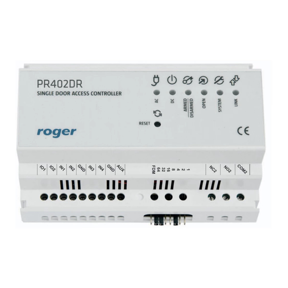
Page 9: Front Panel
Fig. 5 PR402DR front panel 3.2.2 PR402DR-BRD controller According to fig. 6, PR402DR-BRD is equipped with 5 LED indicators and RESET button (S1) on its PCB. RESET button can be used to restart the controller in the same way as in case of powering device off and then on. -
Page 10: Power Supply
3.3 Power supply 3.3.1 PR402DR and PR402DR-BRD controllers Basically, PR402DR and PR402DR-BRD controllers are designed for power supply from 230VAC/18VAC transformer with minimal power output 25VA, but they can also be supplied with 12VDC or 24VDC. The connection of power supply is shown in fig. 7, fig.8 and fig. 9. - Page 11 PR402DR Installation Guide Rev.I.doc 2017-09-18 Fig. 7 PR402DR/PR402DR-BRD controllers supplied with 18VAC Fig. 8 PR402DR/PR402DR-BRD controllers supplied with 24VDC 11/20...
-
Page 12: Pr402Dr-12Vdc And Pr402Dr-12Vdc-Brd Controllers
Controllers can be supplied from single power supply unit if the output power is sufficient. 3.3.2 PR402DR-12VDC and PR402DR-12VDC-BRD controllers PR402DR-12VDC and PR402DR-BRD-12VDC controllers are designed for 12VDC power supply. The supply must be connected according to fig. 10. General guidelines are the same as for PR402DR controllers supplied with 12VDC. 12/20... -
Page 13: Connection Of Door Lock
PR402DR Installation Guide Rev.I.doc 2017-09-18 Fig. 10 PR402DR-12VDC/PR402DR-BRD-12VDC controllers supplied with 12VDC 3.4 Connection of door lock In majority of cases, door locking devices are inductive type. It means that overvoltage (voltage surge) can occur when current flow is interrupted and it can interfere with the controller electronic components. -
Page 14: Communication With Controller
3.6.1 PRT readers, XM expanders and HRT82FK panel (RACS CLK/DTA) PR402DR type controller can operate with two PRT series readers, XM-2 I/O expander, up to four XM-8 expanders dedicated to access control in elevators and HRT82FK function key panel – see fig. -
Page 15: Prt And Third Party Readers (Wiegand And Magstripe)
Wiegand/Magstripe reader does not work properly with the controller, it might be necessary to use PR-GP module. The PR-GP works as electrical interface between reader and controller. In order to determine if PR-GP might be useful, please contact Roger technical support. Fig. 13 Connection of Wiegand/Magstripe readers 3.7 Input and output lines... -
Page 16: Configuration
Following addressing methods are available: By means of jumpers During update of controller firmware by means of Roger ISP software (so called Fixed ID) Manually during Memory Reset procedure By means of PR Master software The first two methods enable configuration of hardware addresses while the remaining two enable configuration of software addresses. -
Page 17: Addressing During Firmware Update (Fixed Id)
PR402DR Installation Guide Rev.I.doc 2017-09-18 Fig. 14 Addressing jumpers 4.1.2 Addressing during firmware update (Fixed ID) FixedID can be set during update of the controller firmware by means of RogerISP software. Prior to firmware upload, RogerISP software offers the possibility to set Fixed ID address in range of 00..99 or disable it (FixedID=None). -
Page 18: Simplified Memory Reset Procedure (Firmware 1.18.6 Or Newer)
PR402DR Installation Guide Rev.I.doc 2017-09-18 4.2.1 Simplified Memory Reset procedure (firmware 1.18.6 or newer) Simplified Memory Reset restores default settings with controller address ID=00. Remove connections to CLK and IN1 terminals Connect CLK with IN1 Restart the controller (press RESET button or switch power supply off/on) - LED OPEN... -
Page 19: Firmware Update
4.4 Firmware update The latest versions of firmware and Roger ISP software are available at www.roger.pl. In order to update firmware it is necessary to connect the device by means of RS485 bus to communication interface (UT-2USB or RUD-1) and then connect the interface to PC with installed Roger ISP software. -
Page 20: Product History
PR402DR Installation Guide Rev.I.doc 2017-09-18 XM-2DR I/O expander. XM-8DR I/O expander (elevator access control). 6. P RODUCT HISTORY Table 8. Product history Product version Released Description PR402DR v.1.0 05/2011 The first commercial version of the product PR402DR v.1.1 02/2012 Modification of built-in converter PR402DR v.1.2...
Need help?
Do you have a question about the PR402DR and is the answer not in the manual?
Questions and answers