
Related Manuals for Roger PR201


Summary of Contents for Roger PR201
- Page 1 R A C S R o g e r A c c e s s C o n t r o l S y s t e m Access controller with integrated proximity reader PR201 Version 2.1 Installation and programming manual...
- Page 2 Introduction The PR301 and PR201 controllers are designed for use in access control systems equipped with electric door lock. The PR301 controller has a built-in proximity reader module and 12 digit keypad, PR201 has proximity reader module only, both controllers have three inputs and tree outputs (one relay output and two transistor outputs).
- Page 3 There are few types of terminals including outdoor versions. Notice: The roger access terminals (PRT series) utilize clock and data lines for communication with controller but this standard differs from common CLOCK&DATA format utilized by many producers. Some PRT terminals are also offered with Wiegand and Magstrip standards but such a types are specially marked.
- Page 4 The controller accepts codes consisting from 3 up to 6 digits and cards (proximity transponders) based on the V4001/2 module of EM MICROELECTRONIC – MARIN Switzerland. Note: The PR201 controller can identify users only by cards, the [Dual identification mode] is not available in this model. Transponder module specification: •...
- Page 5 Alarm on controller can also be cleared remotely from PC. When the ALARM output has been programmed to signalize more than one alarm condition, only the highest priority alarm is signalized. Duress entry This function is not available in PR201 controller.
- Page 6 Using cards for digit programming Because the PR201 is not equipped with keyboard, digit programming is performed by multiply readings of the MASTER or INSTALLER card. In User programming mode programming must be done by MASTER card, in Installer programming mode programming must be done by INSTALLER card.
-
Page 7: User Programming Mode
User Programming Mode In order to enter User Programming mode do the following sequence: • When controller stand in ON or OFF mode, • [Enter MASTER ident.] • [Wait until LED OPEN start blink] • [Enter MASTER ident. again In the user programming mode, you can add/delete the NORMAL and SWITCHER identifiers. From this mode you can also go to the Installer Programming mode for detailed setup. -
Page 8: Installer Programming Mode
PR201v2.1UK.doc 02-08-12 [7] – D NORMAL SWITCHER ELETES ALL USERS + [7] Note: The MASTER and INSTALLER identifiers remain. [8] – E NTRY TO THE NSTALLER ROGRAMMING Note: After EEPROM memory RESET the MASTER and also performs the function of the INSTALLER identifier (MASTER = INSTALLER). - Page 9 PR201v2.1UK.doc 02-08-12 Installer Programming mode In the Installer programming mode detailed setup of controller is available. Entry to the installer programming mode can be done only from the User Programming mode by activation of function [8]. After entry to the Installer Programming mode the SYSTEM and CLOSED LED are on.
- Page 10 PR201v2.1UK.doc 02-08-12 [4] - EMPTY [5] – F UNCTION OF THE LARM OUTPUT + [OPTION] [0] ⇒ The ALARM output repeats the ON/OFF condition of the controller (follows SWITCH output) [1] ⇒ The output signalizes the condition : PREALARM [2] ⇒ The output signalizes the condition : DOOR AJAR [3] ⇒...
-
Page 11: Technical Data
PR201v2.1UK.doc 02-08-12 EEPROM RESET – Return to default (factory) settings After EEPROM RESET all existing data in memory are deleted and default values are restored. After EEPROM RESET, operator must program new MASTER identifier. The EEPROM RESET is done in the following way: •... -
Page 12: Installation Recommendations
PR201v2.1UK.doc 02-08-12 Installation The controller should be hung near the controlled passage, far from any sources of heat and moisture. Electric connections should be made with the power supply off according to the drawings shown at the end of this manual. After the first time power supply is switched on, the controller wake in OFF (red) mode with pre-programmed MASTER card and default settings. -
Page 13: Off Mode
ID from 001 to 049 IDENTIFIER LED SYSTEM LED SYSTEM “SWITCHER” WAIT BLINK BLINK ID from 050 to 099 IDENTIFIER IDENTIFIER “SWITCHER” “MASTER” ID from 001 to 049 ON/OFF ON MODE OPEN (ON/OFF IS GREEN) SYSTEM Simplified operation flow chart od PR201 controller PR_040_UK_201.cdr... -
Page 14: User Programming
Exit from PROOGRAMMING MODE ON/OFF ON/OFF USER INSTALLER OPEN OPEN Entry PROGRAMMING PROGRAMMING to the SYSTEM SYSTEM USER PROGRAMING MODE IN 1 INPUT FUNCTION ADD “NORMAL” USER [1] + [OPTION] [1] + [ x ] + [ y ] + [ z ] + [card] IN 2 INPUT FUNCTION [2] + [OPTION] ADD “SWITCHER”... -
Page 15: Eeprom Reset
SHIELD NOTE: use shielded cabels only if strong interferences exists. Comm. Bus Twisted pair of wires recommended. POWER SUPPLY 12Vdc e.g. PS10/20 EEPROM RESET SUPPLY SN220K Reporting input, 4,7k 4,7k 4,7k Can be used for any monitoring purpose Controller SHIELD CLOCK DATA TAMPER... - Page 16 POWER SUPPLY 12Vdc e.g. PS10/20 + 12V PRxx1 Access Controller DOOR TAMPER RS 485 IN 3 IN 2 IN 1 12 V SHLD MASTER UT-2 SLAVE PR Master POWER komputer PC Software RS 232 PC COMPUTER COM 1...COM 4 Max 15 m Downloading PR controllers from PC...
- Page 17 NOTE: PR system communication bus - max. length 1000m. GND terminals of each supply units Twisted pair of wires without shielding are preffered. Shielded cabels can only be used where strong must be connected with additional wire. electric interferences exists. SUPPLY ZONE B POWER SUPPLY...
- Page 18 R o g e r A c c e s s C o n t r o l S y s t e m T h e s t r u c t u r e a c c e s s c o n t r o l s y s t e m R A C S 3 .
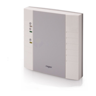
- Page 19 ID selection (valid only for PRT31 terminal) Drilling template 80mm Optional 60 mm diameter ON/OFF OPEN SYSTEM 104 mm 16 mm 16 mm The front and side view of PR201 controller and PRT21 terminal. Scale 1 : 1 Cdr091EN...
Need help?
Do you have a question about the PR201 and is the answer not in the manual?
Questions and answers