
Related Manuals for Roger MCT12M Series


Summary of Contents for Roger MCT12M Series
- Page 1 Roger Access Control System MCT12M Operating Manual Product version: 1.0/2.0 Firmware version: 1.1.18 or newer Document version: Rev. E...
-
Page 2: Design And Application
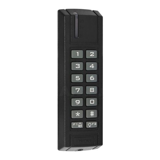
MCT12M Operating Manual 09.07.2020 1. D ESIGN AND APPLICATION The MCT12M is a series of access terminals dedicated to RACS 5 system. Depending on their versions, devices enable identification of users by PINs and/or 13.56 MHz MIFARE® Ultralight/Classic/DESFire/Plus proximity cards. MCT12M is connected to access controller through RS485 interface. - Page 3 MCT12M Operating Manual 09.07.2020 Table 2. Power supply cabling Number of UTP wire pairs for power supply Maximal length of power supply cable 150m 300m 450m 600m Fig. 1 MCT supply from MC16 access controller Fig. 2 MCT supply from dedicated power supply unit 3/17...
- Page 4 MCT12M Operating Manual 09.07.2020 RS485 bus The communication method with MC16 access controller is provided with RS485 bus which can encompass up to 16 devices of RACS 5 system, each with unique address in range of 100-115. The bus topology can be freely arranged as star, tree or any combination of them except for loop.
- Page 5 MCT12M Operating Manual 09.07.2020 Table 1. Input types NO input NC input NO input can be in normal or in triggered state. In NC input can be in normal or in triggered state. In normal state C contacts are opened. Input normal state C contacts are closed.
-
Page 6: Tamper Detector
AN024 application note which is available at www.roger.pl. The technical characteristics of the device are guaranteed for RFID cards supplied by Roger. Cards from other sources may be used, but they are not covered by the manufactures warranty. Before deciding to use specific Roger products with third-party contactless cards, it is recommended to conduct tests that will confirm satisfactory operation with the specific Roger device and software in which it operates. - Page 7 MCT12M Operating Manual 09.07.2020 White IO1 output line Violet IO2 output line Grey-pink REL1 relay normally closed contact Red-blue REL1 relay common contact Pink REL1 relay normally opened contact Fig. 3 Programming jumpers 7/17...
- Page 8 MCT12M Operating Manual 09.07.2020 Fig. 4 MCT12M installation 8/17...
-
Page 9: Operation Scenarios
MCT12M Operating Manual 09.07.2020 Note: MCT12M enclosure consists of front panel and back panel. New device is assembled with a standard back panel, but additional free of charge, extended back panel is included. This panel can be used when connection cable has to be hidden and no flush mounting box is available. Installation guidelines ... -
Page 10: Low Level Configuration (Rogervdm)
MCT12M Operating Manual 09.07.2020 Fig. 6 Typical connection diagram for the –IO version terminal and MC16 access controller 4. C ONFIGURATION Low level configuration (RogerVDM) The purpose of low level configuration is to prepare device for operation in RACS 5 system. Programming procedure with RogerVDM software: 1. - Page 11 MCT12M Operating Manual 09.07.2020 Fig. 7 Connection to RUD-1 interface (low level configuration) Table 6. List of low level parameters Communication settings RS485 address Parameter defines device address on RS485 bus. Range: 100-115. Default value: 100. RS485 communication timeout [s] Parameter defines delay after which device will signal lost communication with controller.
- Page 12 MCT12M Operating Manual 09.07.2020 disabled Range: 0-100. Default value: 100. Short sound after card read Parameter enables short sound (beep) generating by buzzer when card is read. Range: [0]: No, [1]: Yes. Default value: [1]: Yes. Short sound after key press Parameter enables short sound (beep) generating by buzzer when key is pressed.
- Page 13 0-31 and 0-14 for sectors 32-39. Default value: 0. Key type Parameter defines key type used to access sector with PCN. Range: [0]: A, [1]: B, [2]: Roger. Default value: [0]: A. Parameter defines 6 bytes (12 HEX digits) key for accessing sector where PCN is stored.
-
Page 14: Manual Addressing
MCT12M Operating Manual 09.07.2020 First byte position (FBP) Parameter defines the position of the first byte for PCN in data block on card. Range: 0-15. Default value: 0. Last byte position (LBP) Parameter defines the position of the last byte for PCN in data block on card. -
Page 15: Memory Reset Procedure
The purpose of high level configuration is to define logical functioning of the terminal which communicates with the MC16 access controller and it depends on applied scenario of operation. The example of access control system configuration is given in AN006 application notes which is available at www.roger.pl. 5. F IRMWARE UPDATE The update requires connection of device to computer with RUD-1 interface (fig. -
Page 16: Specification
MCT12M Operating Manual 09.07.2020 Fig. 8 Connection to RUD-1 interface (firmware update). 6. S PECIFICATION Table 7. Specification Supply voltage Nominal 12VDC, min./max. range 10-15VDC Current consumption MCT12M-BK/MCT12M-BK-IO/MCT12M-BK-DES-IO: ~65 mA (average) MCT12M/MCT12M-IO/MCT12M-DES-IO:: ~85 mA Inputs Three parametric inputs (IN1..IN3) internally connected to the power supply plus through a 5.6kΩ... -
Page 17: Ordering Information
MIFARE access terminal with keypad; on-board I/Os MCT12M-BK-DES-IO MIFARE DESFire/Plus access terminal; on-board I/Os MCT12M-DES-IO MIFARE DESFire/Plus access terminal with keypad; on-board I/Os RUD-1 Portable USB-RS485 communication interface dedicated to ROGER access control devices 8. P RODUCT HISTORY Table 9. Product history Version...
Need help?
Do you have a question about the MCT12M Series and is the answer not in the manual?
Questions and answers