Table of Contents
Advertisement
Quick Links
Advertisement
Table of Contents

Related Manuals for hattrick RB-4000 M


Summary of Contents for hattrick RB-4000 M
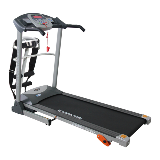
- Page 1 HATTRICK RB-4000 M MOTORIZED TREADMILL OPERATING INSTRUCTIONS MANUAL...
-
Page 2: Important Safety Instructions
IMPORTANT SAFETY INSTRUCTIONS WARNING - Read all instructions before using this treadmill. It is important your treadmill receives regular maintenance to prolong its useful life. Failing to regularly maintain your treadmill may void your warranty. Danger–To reduce the risk of electric shock disconnect your treadmill from the electrical outlet prior to cleaning and/or service work. -
Page 3: Important Electrical Information
IMPORTANT ELECTRICAL INFORMATION WARNING! 1) NEVER use a ground fault circuit interrupt (GFCI) wall outlet with this treadmill. Route the power cord away from any moving part of the treadmill including the elevation mechanism and transport wheels. 2) NEVER operate treadmill on Generator or UPS power supply. 3) NEVER remove any cover without first disconnecting AC power. - Page 4 before starting your workout, especially for the age up to 35 old or once-health problem people. We take no responsible for any troubles or hurts if you don’t following our specification. Treadmill will be carefully assembled and covered the motor shield, then connect to the power. ASSEMBLY INSTRUCTIONS When you open the carton, you will find the below spare parts: PART LISTS...
- Page 5 Assembly tools: 5#Allen wrench 5mm 1pcs、 Wrench with screw driver S=13、14、15 1pcs Notice: Do not get through power before complete assembly Step 1: Open the carton, get out the above spare parts, and put the Main Frame onto the level ground. Step 2: Push up the Console A and Upright tube B towards the arrow direction.
- Page 6 Step 4: Fix the Left & Right Upright Tube Cover(33,34) to the base frame with M5*12 bolt(75) by using Wrench w/ screw driver. Step 5: Use 5# Allen Wrench, drill the Bolt(77) M8*25 through the flat washer(57), spring washer 8(56),then lock the connecting frame(80) onto the left and right upright(4,5).
- Page 7 Step 7: 1. Use 5# Allen Wrench, drill Bolt M8*15 (39) through the spring washer (56), flat washer (57), lock the massage head (78) onto the supporting frame (81) 2. Hang the massage belt (79) onto the massage head (78). ATTENTION:Please confirm complete assembly as the require above and lock all the bolt.
-
Page 8: Folding Instructions
FOLDING INSTRUCTIONS Pulling Up: Put your hand on A position, then pull up the base frame till hearing the sound that the air pressure bar (B) is locked into the round tube Pulling Down: Support place A with one hand, then kick the air pressure bar at the position B, pull down the base frame, then it will fall down automatically ( Please keep anybody and any pet away the... -
Page 9: Technical Parameter
TECHNICAL PARAMETER Set up size(mm) 1735*680*1200MM Voltage As per country Folding size(mm) 890*680*1490MM Output: As per country Running 1220*400 Input: As per country surface(mm) 0.8-12KM/H Speed or 0.8—6KM/H Max. User Weight 120KG SPEED TIME DISTANCE CALORIES PULSE Display GROUNDING METHODS This product must be grounded. -
Page 10: Window Display
OPERATION GUIDE WINDOW DISPLAY: 1.“ speed “ window: Display the speed, the speed range is 0.8--12km/h or 0.8--6km/h, 1 grid means 1 km/h. When setting programes, show PI-P9, when setting mode, show H1-H3. 2. ” time” window: Display running time. Display the exercise time positive direction clock from 0: 00-99:59 ,when count to 99:59, the machine will stop smoothly and show ‘... -
Page 11: Start-Up Quickly(Manual)
any time to start the machine. 4. “ STOP ” button: When the machine is running, press this button to stop any time and all the data will be initial data. 5. “ SPEED +”, “ SPEED –” button: Under initial situation, set the data with this button. When the machine is running, press the button to adjust the speed, 0.1 KM at each press, when press the button over 0.5 seconds, the speed will be up or down continuely 6.”SPEED: 5,8,12”... -
Page 12: Inner Install Program
INNER INSTALL PROGRAM Press “PROGRAM” button SPEED window will display P1-P9 to choose the program you like. Setting of running time, then the TIME window display glittering. Display the advance setting time10:00, press “SPEED+”, “SPEED-” to set up the exercise time what you need. Press “START” button to start the inner install program, the inner install program is divided into 10 sect. -
Page 13: Range Of Program
SPEED RANGE OF PROGRAM Initial Data Initial Set Range Display Range 10:00 TIME(MIN:SECOND) 0:00 5:00-99:00 0:00-99:59 0.8-12(0.8-6) 0.8-12(0.8-6) SPEED(K/h) 1.00 DISTANCE(KM) 0.00 0.50-99.9 0.00-99.9 PULSE(hypo/min) 50-200 CALORIE(THERM) 10-999 0-999 BODY TESTER: At the beginning state, press “ PROGRAM” continuely entering FAT body fat tester, press “ MODE “... -
Page 14: Exercise Instructions
MP3 FUNCTION(OPTIONAL) When the power on, Contacting the external MP3 equipment, the computer will play. The voice is adjustable from the external MP3 equipment, the voice should be adjusted on the proper section to protect the computer loudhailer. CLOSE UP: Switch off the power: You can switch off the power to stop the treadmill, which won’t be damaged at any time. - Page 15 This stage should last for a minimum of 12 minutes although most people start at about 15-20 minutes 3. The Cool Down Phase This stage is to let your Cardio-vascular System and muscles wind down. This is a repeat of the warm up exercise e.g.
-
Page 16: Every Week
WARNING: STOP TREADMILL BEFORE FOLDING. Maintenance and servicing AFTER EACH USE (DAILY) Clean and inspect, following these steps: 1) Turn off the treadmill with the on/off switch, then unplug the power cord at the wall outlet. 2) Wipe down the running belt, deck, motor cover, and console casing with a damp cloth. Never use solvents, as they can cause damage to the treadmill. - Page 17 It may be necessary to lubricate your treadmill running deck at least once every six months to maintain optimal performance of your treadmill. 1) Turn off the treadmill with the start/stop switch, and then unplug the power cord at the wall outlet.
- Page 18 The mat/deck friction may play a major role in the function and life of your treadmill and that is why we recommend you constantly lubricate this friction point to prolong the useful life of your treadmill. You should apply the lubrication after approximately the first 20 hours of operation. We recommend lubrication of the deck every 30 days.
- Page 19 make the running belt stop. If running belt stops, but front roll still runs, under this condition, it means the running belt needs to be adjusted. The adjustment steps for poly V-belt Cut off power firstly and take down the cover of protection. a) Loosen the four screws for the motor, adjust them in a circuit clockwise, then screw down the loose screws.
- Page 20 Center the running belt: DO NOT OVERTIGHTEN the walking belt. This may cause reduced motor performance and excessive roller wear. TO CENTER WALKING BELT: ● Place treadmill on a level surface ● Run treadmill at approximately 3.5 mph ● If the belt has drifted to the right, turn the right adjusting bolt 1/2 turn clockwise and the left adjusting bolt 1/2 turn counterclockwise ●...
-
Page 21: Exploded Drawing
EXPLODED DRAWING... - Page 22 PARTS LIST Base Frame Bolt M8*45 Main Frame Bolt M10*30 Computer Bracket Bolt M6*55 Left Upright Bolt M6*45 Right Upright Bolt M6*35 Motor Bracket Screw M5*16 Fixing pin Screw M5*8 Turnning Bushing Screw S T2.9*8 Front Roller Screw ST4.2*12 Rear Roller Screw ST4.2*25 Wrench w/ screw...
-
Page 23: Troubleshooting
EVA cushion Bolt M5*12 Left upright tube cover Bolt M8*35 Right upright tube cover Bolt M8*25 Bolt Massage head Bolt Massage belt Bolt Connecting frame Bolt M8*35 Supporting frame Bolt M8*15 Foam Bolt M8*20 End cap Bolt M8*30 ARC washer Bolt M8*40 Bolt...
Need help?
Do you have a question about the RB-4000 M and is the answer not in the manual?
Questions and answers