DAVIS Wireless Temperature/Humidity Station Instruction Manual
Fan-aspirated wireless temperature/humidity station
Hide thumbs
Also See for Wireless Temperature/Humidity Station:
- Install manual (12 pages) ,
- Installation manual (12 pages) ,
- Install manual (12 pages)
Table of Contents
Advertisement
Quick Links
Download this manual
See also:
Installation Manual
The Fan-Aspirated Wireless Temperature/Humidity Station, referred to in this
manual as the Aspirated Temp/Hum Station, combines fan aspiration and pas-
sive shielding to minimize the effects of solar radiation, increasing the accuracy
of temperature measurement. This instruction manual takes you step-by-step
through the process of installing and mounting your station.
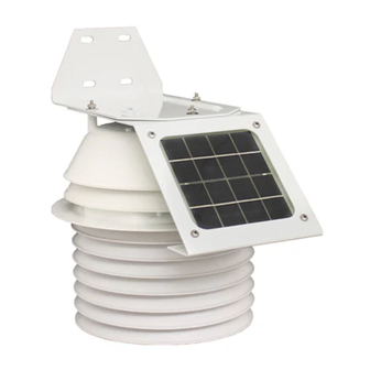
Components
The Aspirated Temp/Hum Station includes these items shown below and on
the next page:
Fan-Aspirated Radiation Shield
F
-A
A N
W
I R E L E S S
T
E M P E R A T U R E
S
T A T I O N
I
N S T A L L A T I O N
Mounting Bracket
Components, Part 1
S P I R A T E D
/H
U M I D I T Y
M
A N U A L
Junction Board Cover
#8 Hex Nuts (3)
#8 Lock Washers (3)
#8 Flat Washers (3)
Product # 6385
Advertisement
Table of Contents

Related Manuals for DAVIS Wireless Temperature/Humidity Station


Summary of Contents for DAVIS Wireless Temperature/Humidity Station
- Page 1 The Fan-Aspirated Wireless Temperature/Humidity Station, referred to in this manual as the Aspirated Temp/Hum Station, combines fan aspiration and pas- sive shielding to minimize the effects of solar radiation, increasing the accuracy of temperature measurement. This instruction manual takes you step-by-step through the process of installing and mounting your station.
-
Page 2: Tools Needed
Choose a location for the station. Mount the station. Page 2 #4 Self-Threading Screws (4) Battery Covers (2) 1.2 Volt Nicad Batteries (2) O-Rings (2) Supplied by customer for wall or post mounting: Components, Part 2 Wireless Temperature/Humidity Station 1/4" x 1-1/2" Lag Screws (4) - Page 3 Disassembling the Station Open up the station by separating the top and bottom parts as shown in the fol- lowing illustrations. Turn the station upside down. Remove the three wing nuts, lock washers and flat wash- ers located on the underside of the station.
- Page 4 Page 4 Upper Section Aspirated Radiation Shield Lower Section Separating the Radiation Shield Sensor Interface Module (SIM) Sensor Interface Cable Locating the Sensor Interface Module Wireless Temperature/Humidity Station Fan Plate Solar Panel Cable (+V SOL) SIM Power Cable (+V SIM)
-
Page 5: Setting The Davistalk Transmitter Id
Insert the 3-volt lithium battery into the battery holder, matching the “+” sign on the battery with the “+” sign on the SIM. Consult this drawing to locate the transmitter ID switches. You will work with them during the next installation step. 3-Volt Lithium Battery SIM Power Cable... - Page 6 When you see the transmitter ID you chose for your station, use the UP or DOWN arrow keys to set the reception of that ID code to “ON”. Page 6 WITCH WITCH Antenna Battery Holder WITCH Transmitter ID Switches Test Indicator LED Wireless Temperature/Humidity Station...
- Page 7 Press the GRAPH key to change the station assigned to that transmitter ID to “TEMP HUM”. To exit Setup Mode, press and hold the DONE key. Viewing Current Temperature and Humidity Press the TEMP key until you see an ‘outside’ temperature displayed on the console screen, with the correct Station No.
- Page 8 Junction Board. Page 8 Installing the Batteries Motor Connector Temp/Hum Sensor Cable Channel Routing the Sensor Cable Wireless Temperature/Humidity Station #4 Screws Battery Cover 1.2 Volt Nicad Battery O-Ring Battery Compartment Fan Unit...
- Page 9 Check the Junction Board cable connections: SIM Sensor, SIM Power (SIM), Motor, Temp/Hum Sensor, and Solar Panel (SOL). Install the Junction Board Cover as show below. The Junction Board Cover presses easily into place when you are installing it. To remove the cover, press gently in on both sides to release the latches holding it in place.
-
Page 10: Testing Transmission From Proposed Location
If you aren’t picking up strong signals where you intend to place your console, better to move the station now than after it has been mounted. Experiment to find the best reception. Page 10 Wireless Temperature/Humidity Station... -
Page 11: Mounting The Station
Mounting the Station The Aspirated Temp/Hum Station can be mounted on a pole or on a vertical surface such as a wooden post, wall or fence. Mounting on a Pole or Mast Mounting the Station Mounting on the Side of a Post or Wall Mounting on the Sensor Arm Page 11... - Page 12 firmly mounted on the pole. Page 12 Mounting Bracket Attaching Temperature/Humidity Station to Mounting Bracket 1/4" Flat Washers 1-1/2" U-Bolts Mounting on a Pole #8 Hex Nuts #8 Lock Washers #8 Flat Washers 1/4" Hex Nuts Wireless Temperature/Humidity Station...
- Page 13 Mounting on a Post or Wall Using four 1/4" x 1-1/2" lag screws (not included), attach the mounting bracket to the surface in the desired location. A mounting template is located on page 15. Drill holes using a 3/16" (5 mm) drill bit. Use a carpenter’s level when marking the holes, to ensure that the bracket will be level.
-
Page 14: Maintenance Instructions
If you are unable to solve the problem, please call Davis Technical Support. We’ll be glad to help. Most questions can be answered while you’re on the phone. You can also email us for support, or visit our website. - Page 15 Diagram of Operation The diagram below shows how the Fan-Aspirated Radiation Shield draws cool outside air up through the sensor chamber and through the walls surrounding the sensor cham- ber. Template for Mounting Holes 1.26" (32 mm) 4.15" (105.5 mm) (71.9 mm) [Either set of 3 holes (A or B) may be used] Troubleshooting...
- Page 16 Connect the equipment into an outlet on a circuit different from that to which the receiver is connected. Consult the dealer or an experienced radio/TV technician for help. Changes or modifications not expressly approved in writing by Davis Instruments may void the user's authority to operate this equipment. Product Number: 6385 Davis Instruments Part Number: 7395.153...
Need help?
Do you have a question about the Wireless Temperature/Humidity Station and is the answer not in the manual?
Questions and answers