Table of Contents
Advertisement
Quick Links
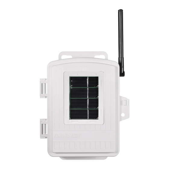
The Wireless Soil Moisture/Temperature Station, referred to in this document
as the Soil Moisture Station, is for use with Wireless Vantage Pro
tions. One Soil Moisture Station can be installed per Vantage Pro Weather Sta-
tion. Up to four WATERMARK soil moisture sensors and four multi-
temperature probes can be installed in a Soil Moisture Station.
Note: The Soil Moisture Station requires Vantage Pro console firmware dated Oct 25
2001 or later. (Press and hold the DONE key then press the UP arrow (+) key to
display the console firmware level.) Contact Davis Technical Support if your
console requires an upgrade. Contact information is located in the back of this
manual.
Components
The Soil Moisture Station includes the following components and mounting
hardware:
Temperature Probe
with 15' (4.6 m) of cable
Soil Moisture Sensor
with 15' (4.6 m) of cable
I R E L E S S
W
O I L
O I S T U R E
S
M
E M P E R A T U R E
T
N S T A L L A T I O N
I
8" Cable Ties
4" Cable Ties
S o i l M o i s t u r e S t a t i o n C o m p o n e n t s
/
T A T I O N
S
A N U A L
M
Shelter
3-Volt Lithium Battery
®
Weather Sta-
Product # 6361
Advertisement
Table of Contents

Related Manuals for DAVIS Soil Moisture/Temperature Station


Summary of Contents for DAVIS Soil Moisture/Temperature Station
- Page 1 The Wireless Soil Moisture/Temperature Station, referred to in this document as the Soil Moisture Station, is for use with Wireless Vantage Pro tions. One Soil Moisture Station can be installed per Vantage Pro Weather Sta- tion. Up to four WATERMARK soil moisture sensors and four multi- temperature probes can be installed in a Soil Moisture Station.
-
Page 2: Tools For Setup
U-Bolts 1/4" Flat Washers 1/4" Lock Washers 1/4" Hex Nuts Tools for Setup In addition to the components shown, you will need some or all of the follow- ing materials: • Adjustable wrench or 7/16" wrench • Ballpoint pen or paper clip (small pointed object of some kind) •... - Page 3 S e n s o r I n t e r f a c e M o d u l e o n S o i l M o i s t u r e S t a t i o n 2.
- Page 4 DIP switches are in the OFF position when each transmitting station leaves the factory. This is true for all of Davis’ wireless equipment. 1. Verify the DavisTalk channel used by your ISS, as well as all other DavisTalk channels already in use by your Vantage Pro Weather Station.
- Page 5 Setting Console/Receiver(s) to Same ID 1. Put your console into Setup Mode — press and hold the DONE key and press the DOWN (-) arrow key. The console will show you Screen 1: Transmitters. You should see the words: “RECEIVING FROM...” and “STATION NO.” followed by the transmitter IDs that your console detects.
-
Page 6: Choosing A Location To Mount The Station
10 seconds. If the LED flashes only once and then remains dark, there is a problem with the transmitter. See “Contacting Davis Technical Support” on page 15. If the LED flashes repeatedly but your console isn’t picking up a signal anywhere in the room, it could be related to one of the following causes: 1. - Page 7 Range of Wireless Transmission The range of wireless transmission depends on many factors. For the best reception, position the transmitter shelter and your console/receiver as close together as possible. The maximum range is up to 400' (120 m) in the line of sight, under optimal conditions.
- Page 8 Mounting the Soil Moisture Station Mounting on a Pole 1. While holding the shelter against the pole, place a U-bolt around the pole and through the two holes on at the top of the shelter. 2. Place a flat washer, a lock washer and a hex nut on each of the bolt ends. U-Bolt 3.
- Page 9 Connecting the Sensors 1. Run the sensor cables up through the grommets on the bottom of the station housing. 2. Connect the temperature probes to the TEMP connectors. 3. Connect soil moisture probes to the SOIL connectors 4. Each matched temperature probe and soil moisture pair must use the match- ing connectors.
- Page 10 6. To prevent fraying or cutting of cables, secure them so they will not whip about in the wind. Secure a cable to a metal pole by wrapping electrical tape around them both. Make sure cables are secure by placing clips or ties approximately every 3 –...
- Page 11 Sprinkler Irrigation • Sprinkler irrigation usually provides a more uniform distribution of water to the ground surface, but there can be great differences in pene- tration and holding capacity due to soil type variations, soil interfaces and contour. Try to place your sensors in the areas where variations occur.
- Page 12 • With coarse, shallow or layered soils, root systems may be limited in depth. • Guidelines on proper depths for specific crops and conditions can be obtained from your local farm advisor. Sensor depth dependent on: • crop rooting depth •...
- Page 13 • Lack of a snug fit is the biggest problem in obtaining good soil moisture sensor readings. • The ideal method of making the access hole is to have a stepped tool. This makes an oversize hole for the upper portion and an exact sized hole at the bottom where the sen- sor is located.
- Page 14 Installation Procedure for Turf/Lawns 1. Cut a slight “V” shaped trench about 5” wide at the top and about 6” deep into the turf--about 6” long. 2. Lift out the turf plug piece you just cut. 3. Press the sensors into the soil at about a 45 degree angle into the side of the trench to set the sensors about 3”-5”...
-
Page 15: Using Soil Moisture Readings
3. Put the sensor back in the water. The reading should run right back to 0 to 5 within 1 to 2 minutes. 4. If the sensor does not pass these tests, please contact Davis Technical Sup- port for help in resolving the problem. -
Page 16: Specifications
Connect the equipment into an outlet on a circuit different from that to which the receiver is connected. • Consult the dealer or an experienced radio/TV technician for help. Changes or modifications not expressly approved in writing by Davis Instruments may void the user's authority to operate this equipment. Product Numbers: 6361 Davis Instruments Part Number: 7395.145...
Need help?
Do you have a question about the Soil Moisture/Temperature Station and is the answer not in the manual?
Questions and answers