DAVIS Temperature/Humidity Sensor Install Manual
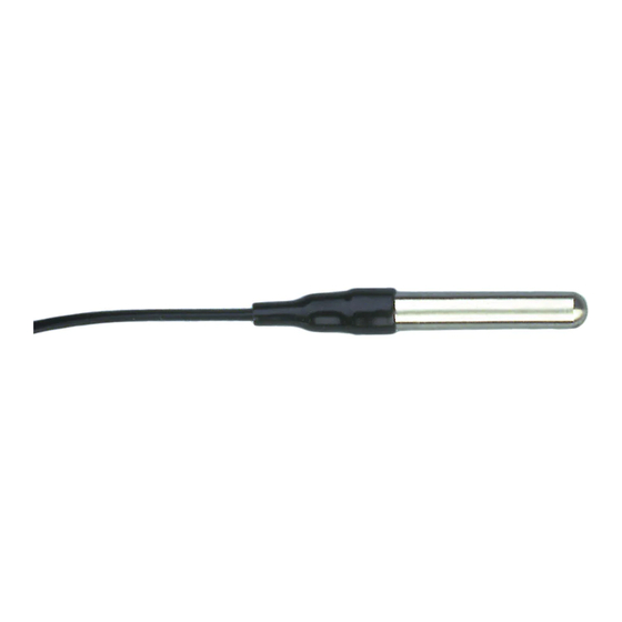
Standard & industrial external temperature sensor & stainless steel temperature probe
Hide thumbs
Also See for Temperature/Humidity Sensor:
- Instruction manual (16 pages) ,
- Installation manual (12 pages) ,
- Install manual (12 pages)
Table of Contents
Advertisement
Quick Links
E
XTERNAL
S
TAINLESS
S
T A N D A R D
The external temperature sensor and the stainless steel temperature probe may
be used with any of Davis' weather stations (except the Perception II
the exception of the GroWeather, the sensor may be used to measure outside
temperature, though you may bury the sensor or immerse it in water to mea-
sure soil or water temperature instead of air temperature. The GroWeather™
allows you to display two separate external temperature readings (or a single
temperature reading and leaf wetness). You may use this sensor for either tem-
perature reading. The standard version of each sensor comes with a 40' (12 m)
cable. The industrial version comes with a 16' (5 m) cable.
T
M
OOLS AND
ATERIALS
You may need some of the following tools and materials in order to complete
your installation. Please be sure you have everything you need before begin-
ning.
Shovel, spade, or hoe to dig hole for sensor when using as soil temperature
Metal or plastic conduit to protect cable from rodents
Cable clips or weather-resistant cable ties with screw holes or other means for
mounting to secure cable
T
S
ESTING THE
ENSOR
Test the sensor before installing it.
1. Attach the sensor cable to the appropriate connector on the junction box/sensor
interface module (SIM).
Consult your station manual or installation manual.
2. Press the appropriate key on your console as necessary to make sure you are getting
an outside, air, or soil temperature reading on the console.
T
EMPERATURE
S
T
TEEL
& I
N D U S T R I A L
N
EEDED
S
ENSOR
EMPERATURE
I
N S T A L L A T I O N
Product #7817, 7818, 7819
&
P
ROBE
M
A N U A L
®)
. With
Advertisement
Table of Contents

Related Manuals for DAVIS Temperature/Humidity Sensor


Summary of Contents for DAVIS Temperature/Humidity Sensor
- Page 1 T A N D A R D The external temperature sensor and the stainless steel temperature probe may be used with any of Davis’ weather stations (except the Perception II the exception of the GroWeather, the sensor may be used to measure outside temperature, though you may bury the sensor or immerse it in water to mea- sure soil or water temperature instead of air temperature.
- Page 2 NSTALLING THE ENSOR Follow the instructions in this section to install your sensor. Make sure you read “Choosing a Location for the Sensor” on page 5 as it contains important information concerning placement of the sensor. Typical Weather Wizard II-S, Weather Wizard III, or Weather Monitor II Installation The illustration below shows a typical installation for the Weather Wizard II-S, Weather Wizard III, or Weather Monitor II.
- Page 3 Typical Standard GroWeather/EnviroMonitor Installation The illustration below shows a typical standard installation for the GroWeather (used to measure air temperature), Energy EnviroMonitor, or the Health Envi- roMonitor. The sensor cable attaches to connector S2 on the sensor interface module (SIM). On GroWeather systems, the sensor can also attach to connector S3 to measure a second temperature (such as soil temperature).
- Page 4 Typical Industrial GroWeather/EnviroMonitor Installation The illustration below shows a typical industrial installation for the GroWeather (used to measure air temperature), Energy EnviroMonitor, or the Health EnviroMonitor. The sensor cable attaches to connector S2 on the sensor interface module (SIM). On GroWeather systems, the sensor can also attach to connector S3 to measure a second temperature (such as soil temperature).
- Page 5 Objects which heat up in direct sunlight or produce radiative cooling effects may affect the temperature readings by changing the surrounding air temperature. Look for a location which satisfies the following requirements (Davis’ Radia- tion Shield provides additional protection for the sensor): Place the sensor in a location where it will not be in direct sunlight and where it will have limited exposure to reflected sunlight.
- Page 6 Using Shielded Extension Cables With the industrial version of the temperature probe, you may use Shielded 2-Twisted Pair extension cables (Product #7884) to extend the sensor cable length. When using Shielded 2-Twisted Pair extension cables, cut off the RED wire at both ends of the cable. Do not splice the red wire to the sensor cable or connect it to the SIM.
- Page 7 ECHNICAL UPPORT Before calling Technical Support (1-510-732-7814), carefully check all cable con- nections from the sensor to the console. Cable connections account for a large portion of the potential problems. Connections should be firmly seated in the jacks and plugged in straight. If you think a connection may be faulty, try jig- gling the cable while looking at the display.
- Page 8 Davis Instruments Part Number: 7395-112 External Temperature Sensor, Stainless Steel Steel Temperature Probe, Standard and Industrial Rev. C Manual (7/8/99) This product complies with the essential protection requirements of the EC EMC Directive 89/336/EC. © Davis Instruments Corp. 1997. All rights reserved.
Need help?
Do you have a question about the Temperature/Humidity Sensor and is the answer not in the manual?
Questions and answers