DAVIS Temperature/Humidity Sensor Install Manual
Standard & industrial external temperature/ humidity sensor
Hide thumbs
Also See for Temperature/Humidity Sensor:
- Instruction manual (16 pages) ,
- Install manual (12 pages) ,
- Installation manual (12 pages)
Advertisement
Quick Links
The External Temperature/Humidity Sensor (T/H Sensor), may be used with
the Weather Monitor II
Health EnviroMonitor
and humidity-related conditions. For a complete list of the conditions you may
display using the T/H Sensor, consult your station manual.
Components
The T/H Sensor includes the following components. Please make sure you
have all listed components before continuing.
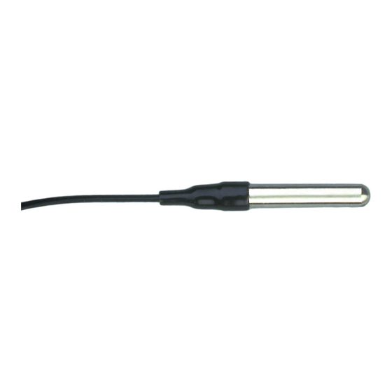
Temperature/Humidity Sensor with cable
The standard version comes with a 40' (12 m) cable. The industrial ver-
sion comes with a 16' (5 m) shielded cable.
Five #4 x 1/2" pan headself-threading screws
One #4 Flat Washer
One Cable Clamp
Tools and Materials Needed
In addition to the components listed above, you will need the following tools
and materials. Please be sure you have everything you need before beginning
the installation.
Small Phillips-head screwdriver
Drill and 1/16" to 3/32" (#43, 2 mm) drill bit.
Cable clips or weather-resistant cable ties with screw holes or other
means for mounting. Do not use staples.
S
T A N D A R D
E
X T E R N A L
H
U M I D I T Y
I
N S T A L L A T I O N
®
®
, GroWeather
, Energy EnviroMonitor
®
. The T/H Sensor enables you to display temperature
& I
N D U S T R I A L
T
E M P E R A T U R E
S
E N S O R
M
A N U A L
®
, and the
Product # 7859 & 7860
/
Advertisement

Related Manuals for DAVIS Temperature/Humidity Sensor


Summary of Contents for DAVIS Temperature/Humidity Sensor
- Page 1 The External Temperature/Humidity Sensor (T/H Sensor), may be used with the Weather Monitor II Health EnviroMonitor and humidity-related conditions. For a complete list of the conditions you may display using the T/H Sensor, consult your station manual. Components The T/H Sensor includes the following components. Please make sure you have all listed components before continuing.
- Page 2 “Choosing a Location for the T/H Sensor” on page 4 as it contains impor- tant information concerning placement of the sensor. Typical Weather Monitor II Installation The illustration below shows a typical T/H Sensor installation for the Weather Monitor II. Page 2 Typical Weather Monitor II installation Standard & Industrial External Temperature/Humidity Sensor...
- Page 3 Note: You may also use the Radiation Shield and Sensor Mounting Arm (pictured below) if desired. Typical Standard GroWeather/EnviroMonitor Installation The illustration below shows a typical Standard T/H Sensor installation for the GroWeather, Energy EnviroMonitor, or the Health EnviroMonitor. Typical standard GroWeather/EnviroMonitor installation Installing the T/H Sensor Page 3...
- Page 4 Page 4 Standard & Industrial External Temperature/Humidity Sensor...
- Page 5 Look for a location which satisfies the following requirements: Ideally, install the sensor in a Davis radiation shield. Place the sensor in a location shielded from rain and other sources of water such as rainfall runoff. CAUTION: It is important that no water strike the sensor.
- Page 6 Mounting the T/H Sensor in a Davis Radiation Shield In order to attach the External Temperature/Humidity Sensor (T/H Sensor) to the Radiation Shield, you will need to expose the Radiation Shield’s closed plate. Refer to your Radiation Shield installation manual for complete instruc- tions on mounting the Radiation Shield.
- Page 7 If using the industrial version of the sensor, secure the cable to the mounting surface using the cable clamp, a #4 x 1/2" screw, and a #4 washer. Connect the sensor cable to the junction box/SIM. Routing Sensor Cable To prevent fraying or cutting of the cable where it is exposed to weather, it is important that you secure it so it doesn’t whip about in the wind.
- Page 8 Secure the front piece by replacing the two screws. Page 8 Removing the front pieece Connecting the sensor cabble Standard & Industrial External Temperature/Humidity Sensor...
- Page 9 Displaying Dew Point on the Weather Monitor II Follow the directions below to use the dew point function on your Weather Monitor II. For a description of dew point, consult the appropriate section of the Weather Monitor II manual. Note: Instructions for displaying dew point are contained in the GroWeather, Energy EnviroMonitor, and Health EnviroMonitor manuals.
- Page 10 The display will show 2˚F (1˚C) which is the only possible setting for the dew point alarm. Press any key to exit. The alarm sounds if dew point and temperature are within 2˚F (1˚C). Page 10 Dew point alarm Standard & Industrial External Temperature/Humidity Sensor...
-
Page 11: Troubleshooting
If, after checking these procedures you are unable to solve the problem, contact Davis Technical Support for further instructions (See “Contacting Davis Instruments Technical Support” on page 12). Please do not return your unit for repair without receiving prior authorization. -
Page 12: Specifications
Contacting Davis Instruments Technical Support If you have any questions about our products, please call Davis Technical Sup- port. We’ll be glad to help. Most questions can be answered while you’re on the phone. You can also email us for support, or visit our website. Sorry, we are unable to accept collect calls.
Need help?
Do you have a question about the Temperature/Humidity Sensor and is the answer not in the manual?
Questions and answers