Table of Contents
Advertisement
Quick Links
The Wireless Temperature/Humidity Station, referred to as the Temp/Hum
Station in this manual, is for use with Wireless Vantage Pro
Components
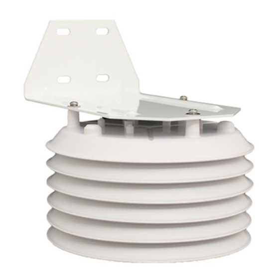
The Temp/Hum Station consists of a temperature and humidity sensor located
in a radiation shield, plus a sensor interface module and transmitter located in
a protective housing.
1-1/2" U-Bolts
1/4" Flat Washers
1/4" Hex Nuts
3-Volt
Lithium
Battery
Sensor Interface Module Housing
Tools for Setup
In addition to the hardware provided, you will need some or all of the follow-
ing materials:
• Small Phillips-head screwdriver
• Adjustable wrench or 11/32" wrench and 7/16" wrench
• Ballpoint pen or paper clip (small pointed object of some kind)
• Drill and 3/16" (5 mm) drill bit (if mounting on a flat, vertical surface)
• Four 1/4" x 1-1/2" (6 x 38 mm) lag screws (if mounting on a flat, vertical
surface) and a wrench to fit the lag screw hex head.
W i r e l e s s
Temp e r at u r e/H u mi di ty
Stat i o n
I n s tal l at i o n Ma n u al
For Vantage Pro
Radiation Shield
Assembly
®
or Vantage Pro Plus
Mounting
Bracket
™
®
weather stations.
Product # 6380
Advertisement
Table of Contents

Subscribe to Our Youtube Channel
Related Manuals for DAVIS 6380 Wireless Temperature/Humidity Station


Summary of Contents for DAVIS 6380 Wireless Temperature/Humidity Station
-
Page 1: Tools For Setup
W i r e l e s s Temp e r at u r e/H u mi di ty Stat i o n I n s tal l at i o n Ma n u al ® ™ For Vantage Pro or Vantage Pro Plus The Wireless Temperature/Humidity Station, referred to as the Temp/Hum Station in this manual, is for use with Wireless Vantage Pro... -
Page 2: Table Of Contents
• Testing Transmission from Proposed Location, page 7 • Mounting the Temp/Hum Station, page 8 • A Note on Securing Cables, page 11 See “Maintenance” on page 10. For Technical Support, see “Contacting Davis Instruments” on page 11. Preparing the Temp/Hum Station... -
Page 3: Applying Power
5. Fasten the mounting bracket in place using the three long screws as shown in the illustration below. 4" Bolts Re-install Mounting Bracket Lock Washers Flat Washers Radiation Shield Assembly Applying Power 1. Turn the main part of the ISS upside down. This is the part that includes the rain collector and the radiation shield. -
Page 4: Setting The Transmitter Id
3. Verify that the temp/hum sensor cable is plugged into the receptacle labeled “TEMP HUM” on the SIM. 3-Volt Lithium Battery (wireless models only) Cable Routing Channels (press cables fully into channel) Temp/Hum Transmitter ID DIP Switches Temp/Hum Station Sensor Interface Module (SIM) 4. -
Page 5: Setting Console Station Id On The Console
ID C WITCH WITCH WITCH (default) Use this table to ensure that each wireless transmitting station in your system is broadcasting on its own transmitter ID. Battery Holder Transmitter ID Switches Test Indicator LED DIP Switches in Top-right Corner of SIM (Illustration has been enlarged for clarity) Setting Console Station ID on the Console 1. -
Page 6: Setting The Console Station Id Using Weatherlink
10 seconds. If the LED flashes only once and then remains dark, there is a problem with the transmitter. See “Contacting Davis Instruments” on page 11. If the LED flashes repeatedly but your console isn’t picking up a signal... -
Page 7: Choosing A Location For The Temp/Hum Station
3. Reception is being disrupted by RF (radio frequency) interference. 4. There is a problem with the console. See “Contacting Davis Instruments” on page 11. Note: Remember to set the Test DIP switch OFF when you’re finished testing wireless transmission. If it is left ON, the blinking LED will reduce battery life significantly. -
Page 8: Mounting The Temp/Hum Station
Mounting the Temp/Hum Station The Temp/Hum Station can be mounted on a pole or on a vertical surface such as a wooden post or wall. Mounting on a Pole Use a pole having an outside diameter between 1" and 1-1/4" (25 – 31 mm). 1. - Page 9 Mounting on a Vertical Surface 1. Using four 1/4" x 1-1/2" lag screws (not included), attach the mounting bracket to the surface in the desired location. Drill holes using a 3/16" (5 mm) drill bit. Use a carpenter’s level when mark- ing the holes, to ensure that the bracket will be level.
- Page 10 Maintenance • The ability of the radiation shield to keep fresh air flowing over the sen- sors will be reduced if the shield plates become dirty. Clean the surfaces of the shield plates periodically with a damp cloth. • Keep areas between the shield plates free of debris that may obstruct air flow.
-
Page 11: A Note On Securing Cables
Contacting Davis Instruments If you have questions about your Temp/Hum station, or encounter problems installing or operating the station, please contact Davis Technical Support. Note: Please do not return items to the factory for repair without prior authorization. (510) 732-7814 for Technical Support, Monday – Friday, 7:00 a.m. – 5:30 p.m. - Page 12 Connect the equipment into an outlet on a circuit different from that to which the receiver is connected. • Consult the dealer or an experienced radio/TV technician for help. Changes or modifications not expressly approved in writing by Davis Instruments may void the user's authority to operate this equipment. Product Numbers: 6380 Davis Instruments Part Number: 7395.142...
Need help?
Do you have a question about the 6380 Wireless Temperature/Humidity Station and is the answer not in the manual?
Questions and answers