Table of Contents
Advertisement
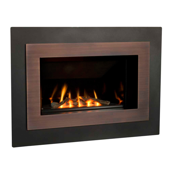
Direct Vent Gas Fireplace Heater
WARNING: If the information in these
instructions is not followed exactly, a fi re
or explosion may result causing property
damage, personal injury or loss of life.
Do not store or use gasoline or other
fl ammable vapors and liquids in the vicinity
of this or any other appliance.
WHAT TO DO IF YOU SMELL GAS
• Do not try to light the appliance.
• Do not touch any electrical switch; do not
use any phone in your building.
• Immediately call your gas supplier from
a neighbor's phone. Follow the gas
supplier's instructions.
• If you cannot reach your gas supplier, call
the fi re department.
Installation and service must be performed
by a qualifi ed installer, service agency or the
gas supplier.
4001955-12
© 2011, Miles Industries Ltd. All rights reserved.
H4 S
Model 650ILN (Natural Gas)
Model 650ILP (Propane)
Installation & Operating Instructions
HOT GLASS WILL
CAUSE BURNS.
DO NOT TOUCH GLASS
UNTIL COOLED.
NEVER ALLOW CHILDREN
TO TOUCH GLASS.
Manufactured by
MILES INDUSTRIES LTD., British Columbia, Canada
www.valorfi replaces.com
ERIES
INSTALLER: Leave this manual
with the appliance.
CONSUMER: Retain this manual
for future reference.
Please read this manual BEFORE
installing and operating this
appliance.
This appliance may be installed in an
after-market permanently located,
manufactured (mobile) home where not
prohibited by local codes.
This appliance is only for use with the type
of gas indicated on the rating plate. This
appliance is not convertible for use with
other gases, unless a certifi ed kit is used.
This appliance is a domestic room-heating
appliance. It must not be used for any other
purposes such as drying clothes, etc.
This appliance is suitable for installation in a
bedroom or bed sitting room.
Massachusetts: The piping and fi nal
gas connection must be performed by a
licensed plumber or gas fi tter in the State of
Massachusetts. Also, see Carbon Monoxide
Detector requirements under "Safety and
Warning Information" on page 5.
Advertisement
Table of Contents

Related Manuals for Valor 650ILN


Summary of Contents for Valor 650ILN
- Page 1 H4 S ERIES Model 650ILN (Natural Gas) Model 650ILP (Propane) Direct Vent Gas Fireplace Heater Installation & Operating Instructions HOT GLASS WILL CAUSE BURNS. INSTALLER: Leave this manual with the appliance. DO NOT TOUCH GLASS CONSUMER: Retain this manual UNTIL COOLED.
- Page 2 For purchasing a Valor by Miles Industries. Your new radiant gas heater is a technical appliance that must be installed by a qualifi ed dealer. Each Valor fi replace is fully tested during the production process for your safety and comfort.
-
Page 3: Table Of Contents
Table of Contents Safety and Warning Information ..............4 Specifi cations ....................7 Overview.....................8 Dimensions ....................9 Framing ....................10 Location ....................11 Venting ......................11 Co-Axial Venting ..................12 Co-Linear Venting ..................18 Appliance Preparation ................19 Gas Supply Installation ................22 Liner Panels Installation .................23 Ceramic Logs Installation ...............24 Window Refi... -
Page 4: Safety And Warning Information
Safety and Warning Information READ and UNDERSTAND all instructions carefully This unit MUST be used with a vent system as before starting the installation. FAILURE TO described in this installation manual. NO OTHER vent FOLLOW these installation instructions may result in system or components MAY BE USED. - Page 5 Safety and Warning Information a. In the event that the side wall horizontally vented Operating Your Fireplace for the First Time gas fueled equipment is installed in a crawl space or When operating your new fi replace for the fi rst time, an attic, the hard wired carbon monoxide detector with some vapors may be released due to the burning of alarm and battery back-up may be installed on the next...
- Page 6 Safety and Warning Information (c) MANUFACTURER REQUIREMENTS - GAS EQUIPMENT VENTING SYSTEM PROVIDED. When the manufacturer of Product Approved side wall horizontally vented gas equipment provides a venting system design or venting system components with the equipment, the instructions provided by the manufacturer for installation of the equipment and the venting system shall include: 1.
-
Page 7: Specifi Cations
Approvals & codes Supply Gas These appliances are certifi ed by ANSI Z21.88-2009/CSA Heater engine unit 650ILN is used with natural gas 2.33-2009 American National Standard / CSA Standard installations. for Vented Gas Fireplace Heaters for use in Canada and Heater engine unit 650ILP is used with propane gas USA. -
Page 8: Overview
Overview Framing—See Framing section Field convertible Remote Handset Wall Holder from top to rear outlet Min. 3/4” (19 mm) Fire On/Off Wall Switch 650IL Combustible framing allowed beneath Wall Finish fi replace. When May be combustible material. the appliance is NOTE: Finished wall surface, installed directly on carpeting, tile or... -
Page 9: Dimensions
Dimensions 8-1/4” (210 mm) From finished wall surface to top vent MINIMUM 3/4” (19 mm) from finished Stand-off wall surface to front of 3” (76 mm) min. appliance To side wall from inner frame in front of the appliance See table 36”... -
Page 10: Framing
Framing • A non-combustible hearth is not necessary in front of this appliance. • Note that the unit is installed at the framing stage and fi xed to framing using support angles. See page 20. The wall fi nish is then installed over the support angles up to the front frame on the unit, on the sides and up to the stand-offs on the top. -
Page 11: Location
Location Venting Vent Material Vent Penetration through Walls & Ceilings This unit is approved for installation using 4 by 6-5/8 Combustible: When penetrating through combustible inches diameter approved co-axial direct vent pipes walls and ceilings, frame a minimum of 10 inch by and accessories listed on pages 37–38 of this guide. -
Page 12: Co-Axial Venting
Co-Axial Venting Typical Co-Axial Venting Components VERTICAL TERMINATION STORM COLLAR FLASHING ATTIC INSULATION SHIELD ATTIC FIRESTOP CEILING FIRESTOP HORIZONTAL 2-PIECE TERMINATION 90˚ ELBOW PIPE WALL PIPE LENGTH THIMBLE LENGTH PIPE LENGTH PIPE LENGTH 817VAK 817VAK... - Page 13 Co-Axial Venting Co-Axial Venting Rear Vent with No Vertical Rise The horizontal vent run cannot be extended by the use of any vent accessory pipes. Vent pipe max. 15” (381 mm) 26” (660 mm) max. after 45° elbow vent length (14”...
- Page 14 Co-Axial Venting Horizontal Vent Termination Location • The vent terminal must be located on an outside wall or through the roof. • This direct vent appliance is designed to operate when an undisturbed airfl ow hits the outside vent terminal from any direction.
- Page 15 Co-Axial Venting Co-Axial Venting Confi gurations with Vertical Rise 4 x 90º ELBOWS MAXIMUM (or equivalent) 3” min. above top of horizontal pipe 1” min. all around vertical pipe 1” min. around bottom & sides of horizontal pipe Min. 6” rise for top outlet Min.
- Page 16 Co-Axial Venting 5. Each 90 degrees elbow installed on the horizontal How to Read the Venting Chart plane is equivalent to a 3 feet horizontal pipe; The chart below applies to co-axial roof or wall therefore, 3 feet must be subtracted from allowable termination in installations with vertical rise.
- Page 17 Co-Axial Venting Co-Axial Vertical Installations Overhang should • Check the roof pitch to determine which roof not extend beyond vent if within 48” of fl ashing will be needed. See venting accessories list Horizontal termination cap on pages 37–38 for allowable components. overhang •...
-
Page 18: Co-Linear Venting
Rear or Top Outlet Conversion to Co-Linear NOTE: Min. 1/2” Co-linear Co-linea Liners using Valor 556CLA Co-Linear Adapter. adapter adapter gap required for air flow (Generic co-axial to co-linear adapter boxes may also be used as an alternate to the 556CLA). -
Page 19: Appliance Preparation
8 screws. 5. Fit the outer collar over inner collar. Loosely fi t the 12 screws. Place the adapter 817VAK or Valor terminal kit 551DVK over the collars to check alignment. Tighten the 12 screws to secure the outer collar. - Page 20 Appliance Preparation Stand-off and Support Angles Installation Thickness of wall finish + extra 3/4” (19 mm) and Fitting (Appliance MUST project 3/4” (19 mm) in front of the wall finish surface) The distance from the support angles to the front face Fix to appliance of the heater case is adjustable to allow for a range of case with...
- Page 21 Appliance Preparation Air Restrictors Fitting No restrictors are required for appliances which only have a horizontal vent run. If installing an appliance which has a rear vent outlet connection and no vertical vent pipe rise, ignore this stage. A restrictor set, shown right, is supplied with each 650 engine unit. The restrictors cover part of the inlet air openings in the fi...
-
Page 22: Gas Supply Installation
Gas Supply Installation • The gas supply pipe should enter the appliance case through the opening at the left side. The supply pipe should be connected to the appliance gas inlet pipe situated at the left side of the control valve. Supply line connection to the inlet pipe is 3/8 inch NPT ( female). -
Page 23: Liner Panels Installation
Liner Panels Installation All liner panels can be installed as indicated below. 4. Insert the top panel over the left side panel while Unpack the liners carefully to avoid scratching or holding the top panel forward up the slope. Rotate damaging them. -
Page 24: Ceramic Logs Installation
Ceramic Logs Installation Unpack the ceramic logs very carefully to avoid damaging their fragile material. Install the logs as shown below. Please note that the position of the logs is critical to insure the good performance of the appliance. 1. Place the rear log centering it side to side in the 4. -
Page 25: Window Refi Tting & Baffl E Installation
Window Refi tting & Baffl e Installation 1. Slide the window inside the appliance case and rest it on the fi rebox front bottom tabs. Refi t the bottom two bolts. The bolts should be screwed in securely. 2. Refi t the top two bolts securing by turning them through 90 degrees. -
Page 26: Wall Switch Kit Installation
Wall Switch Kit Installation 4. Take the switch wire and plug it into the receiver’s CAUTION connection slot as indicated (the other slot should already be fi tted with the valve’s wire harness DO NOT PUT BATTERIES IN THE REMOTE connector). -
Page 27: Remote Control Initial Set-Up
Remote Control Initial Set-up The receiver and the handset of the remote control system must be initially synchronized before the fi rst use. 1. Insert alkaline batteries in the remote control receiver and handset. The receiver is located left of the control valve under the burner module. -
Page 28: Remote Control Handset Wall Holder Installation
Remote Control Handset Wall Holder Installation The remote control kit for this fi replace comes Alternative 2 complete with a wall-mounted holder. This Packing Contents: Alternative 3 holder is not required in all installations but 1 Wall Bracket A is provided as an optional feature for those 2 Screws B 1 Screw C customers who wish to mount the remote... - Page 29 Owner’s Information • Use a soft damp cloth to apply the cleaner. Dry the 4. Grab the top of the window and baffl e and pull them glass with a soft, dry, preferably cotton cloth. Most forward and release to check that the window opens paper towels and synthetic materials are abrasive to slightly and returns confi...
- Page 30 Owner’s Information Batteries Fireplace Control Devices There are two ways to control your fi replace. CAUTION 1. Thermostatic Remote Control DO NOT USE a screwdriver or other metallic object 2. Wall Switch to remove the batteries from the receiver or the handset! This could cause a short circuit to the receiver.
-
Page 31: Remote Control Operation
Remote Control Operation NOTE: Before using the remote control system for the fi rst time, the receiver and the handset must be synchronized. See the section Remote Control Initial Set-up on page 27 in this manual. Your fi replace remote control helps you get the comfort, convenience and aesthetics you want from your gas fi replace. The remote controls your fi... - Page 32 Remote Control Operation Operation Modes STANDBY MODE—Ignited pilot only. MAN MODE —Manual Mode. You can use this mode to adjust the flame height up or down. ☼ TEMP MODE —Daytime Temperature Mode (appliance must be in Standby mode; pilot ignited): The room temper- TEMP ature is measured and compared to the set temperature.
- Page 33 Remote Control Operation Temperature Use this setting when you come in and want to enjoy a set temperature. MODE or the ☽ 1. Select either the ☼ MODE by briefly pressing the SET button. TEMP TEMP 2. Hold the SET button until the TEMP display flashes. 3.
-
Page 34: Options
It may be fi tted before the 620FBL—Fluted Black Liner (Ceramic) fi replace is installed or retrofi tted at a later date 621VRL—Valor Red Brick Liner (Ceramic) provided power is available. 622LSL—Ledgestone Liner (Ceramic) NOTE: The power supply to the fan should be... -
Page 35: Lighting Instructions
Lighting Instructions FOR YOUR SAFETY, READ BEFORE LIGHTING WARNING: If you do not follow these instructions exactly, a fi re or explosion may result causing property damage, personal injury or loss of life. A. This appliance has a pilot which must be lighted by hand, remote control, or wall switch. Follow these instructions exactly. -
Page 36: Wiring Diagram
Wiring Diagram Wall Switch Kit Connector Yellow GV60 Wiring Diagram... -
Page 37: Approved Venting Components
Approved Venting Components APPROVED DIRECT VENT SUPPLIERS FOR VALOR MODELS 530, 534, 535, 650, AND MF28 Venting Parts Code / availability by Manufacturer Venting Parts Description Co-axial Kit, 26” long — — — — — 551DVK Standard Co-axial 46DVA-HC 4DT-HC TM-4HT —... - Page 38 835TG Notes: All listed above co-axial pipes and fi ttings require Valor 817VAK Adapter Kit to fi t Valor’s smooth collars. 2) Follow instructions supplied with each manufacturer’s components. 3) Unless otherwise specifi ed, all the parts and assemblies from the above table are to be used with 4” x 6-5/8” pipes.
-
Page 39: Warranty
Warranty If you have a problem with this unit, please contact your dealer or supplier immediately. Under no circumstances should you attempt to service the unit in any way by yourself. The warranties in paragraphs 1 and 2 are provided only to the fi rst purchaser/user of this unit, are not transferable and are subject to the conditions and limitations in paragraphs 3, 4 and 5. -
Page 40: Replacement Parts
Air shutter cover NG 4002346 Enamel black 618EBL Air shutter slider LPG 320B293 Ceramic fl uted black 620FBL Air shutter slider NG 4002345 Valor red brick 621VRL Burner NG 740K189 Ledgestone 622LSL Burner LPG 740K190 Rear panel Injector elbow 82-650 NG... - Page 42 Thank You ... For purchasing a Valor by Miles Industries. Your new radiant gas heater is a technical appliance that must be installed by a qualifi ed dealer. Please circle where appropriate - ask your installer if in doubt:Information provided will be used for customer records only.
- Page 43 Fold here Postage needed Miles Industries Ltd. 190 - 2255 Dollarton Highway North Vancouver, BC V7H 3B1 Canada Online Warranty registration at www.valorfi replaces.com Were you given all documentation and manuals for your product? Thank you for choosing a Valor Product...
Need help?
Do you have a question about the 650ILN and is the answer not in the manual?
Questions and answers