Table of Contents
Advertisement
Quick Links
Advertisement
Table of Contents

Related Manuals for AIC FB127-LX


Summary of Contents for AIC FB127-LX
- Page 1 FB127-LX Server Barebone User's Manual UM_FB127-LX_v1.3_110819...
-
Page 2: Table Of Contents
Table of Contents Preface ������������������������������������������������������������������������������������������������ i Safety Instructions ����������������������������������������������������������������������������� ii About This Manual ����������������������������������������������������������������������������� iv Chapter 1� Product Features ������������������������������������������������������������� 1 1�1 Box Contents ����������������������������������������������������������������������������������� 1 1.2 Specifications����������������������������������������������������������������������������������� 2 1�3 Feature ��������������������������������������������������������������������������������������������� 3 Chapter 2� Hardware Setup ��������������������������������������������������������������� 6 2�1 Central Processing Unit Setup ��������������������������������������������������������� 6 2.1.1 Processor Installation .................. - Page 3 4.3.1 Main ........................46 4�4 Advanced ����������������������������������������������������������������������������������������� 47 4.4.1 Peripheral Configuration ................... 47 4.4.2 Video Configuration ................... 47 4.4.3 OEMBoard Function ................... 47 4.4.4 SIO AST2500 ...................... 48 4.4.5 Socket Configuration ..................48 4.4.6 ME Configuration ....................54 4.4.7 PCH Configuration ..................... 55 4.4.8 H2O IPMI Configuration ..................
- Page 4 Document Release History Release Date Version Update Content User's Manual release to public. 2018 August 1.Cover update. 2019 September Motherboard setting update. 2019 1. Pin definition update. November 2019 2. SW update.
- Page 5 Copyright © 2018 AIC, Inc� All Rights Reserved� This document contains proprietary information about AIC products and is not to be disclosed or used except in accordance with applicable agreements.
-
Page 6: Preface
Disclaimer AIC shall not be liable for technical or editorial errors or omissions contained herein. The information provided is provided "as is" without warranty of any kind. To the extent permitted by law, neither AIC or its affiliates, subcontractors or suppliers will be liable for incidental, special or consequential damages including downtime cost;... -
Page 7: Safety Instructions
Safety Instructions Before getting started, please read the following important cautions: • All cautions and warnings on the equipment or in the manuals should be noted. • Most electronic components are sensitive to electrical static discharge. Therefore, be sure to ground yourself at all times when installing the internal components. •... - Page 8 • If one of the following situations arise, the equipment should be checked by service personnel: 1. The power cord or plug is damaged. 2. Liquid has penetrated the equipment. 3. The equipment has been exposed to moisture. 4. The equipment does not work well or will not work according to its user manual. 5.
-
Page 9: About This Manual
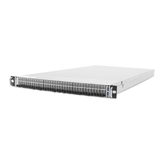
FB127-LX. Chapter 1 Product Features FB127-LX is a flexible storage server barebone that is specifically designed to accommodate diverse corporations and enterprises for managing heavy workloads and multiple applications. -
Page 10: Chapter 1� Product Features
Chapter 1. Product Features Chapter 1. Product Features FB127-LX is a high density storage server that includes mother board, chassis, redundant power supplies, HDD backplane, and hotswapple fans. For more information about our product, please visit our website at http://www.aicipc.com/en. -
Page 11: Specifications
FB127-LX User Manual Chapter 1. Product Features 1.2 Specifications mm : 438 x 801.2 x 44 RC-PE1U14-TY 1 x8 PCIe slot Dimensions Riser Card (W x D x H) (included) inches : 17.2 x 31.5 x 1.7 1 x16 PCIe slot... -
Page 12: 1�3 Feature
Chapter 1. Product Features 1�3 Feature FB127-LX is a reliable 2U storage server barebone with 24 hotswap drives bays at the front and 2 hotswap drive bays at the rear. This product is designed to accommodate the AIC-patented serverboard, Lynx, which supports two Intel® Xeon® Scalable Processors and 24 DDR4 DIMM to offer greater perfomance, efficiency, and utility for our customers. - Page 13 FB127-LX User Manual Chapter 1. Product Features Front Panel Item Description Item Description Power Button LAN Activity LED Power Status LED System Alert LED Drive Activity LED 2 x USB 3.0 Type A port Rear Panel ...
- Page 14 FB127-LX User Manual Chapter 1. Product Features Top View Lynx Serverboard Item Description 7 x 40x56 easy swap fans...
-
Page 15: Chapter 2� Hardware Setup
Chapter 2� Hardware Setup FB127-LX User Manual Chapter 2. Hardware Setup This section describes a simple instruction guide for installing the hardware components on the serverboard system. Turn off and unplug all system and peripheral devices before proceeding. 2�1 Central Processing Unit Setup The serverboard supports dual Xeon scalable processors and Socket P0 (LGA-3647). - Page 16 FB127-LX User Manual Chapter 2. Hardware Setup Processor Socker Assembly: The server board includes two processor sockets (LGA-3647), supports two Intel® Xeon® Processor Scalable Family and has a Thermal Design Power (TDP) of up to 165W on selected models. PHM (Processor Heatsink Module) Component:...
- Page 17 FB127-LX User Manual Chapter 2. Hardware Setup PHM Screw Installation Order: The PHM sits level with the processor socket assembly. The PHM is NOT installed properly if it does not sit level with the processor socket assembly. Once the PHM is seated over the processor socket assembly, the four heat sink torque screws must be secured in the following order as shown below.
-
Page 18: 2�2 System Memory
FB127-LX User Manual Chapter 2. Hardware Setup 2�2 System Memory 2�2�1 Placement CPU1 JDIMMJ1 JDIMMJ0 JDIMMK1 JDIMMK0 JDIMML1 JDIMML0 JDIMMC0 JDIMMC1 JDIMMB0 JDIMMB1 JDIMMA0 JDIMMA1 CPU0 JDIMMD1 JDIMMD0 JDIMME1 JDIMME0 JDIMMF1 JDIMMF0... -
Page 19: Dimm Population
FB127-LX User Manual Chapter 2. Hardware Setup 2�2�2 DIMM Population DIMM DIMM Numbers Placement Numbers CPU1 CPU0 JDIMMI1 JDIMMC1 JDIMMH0 JDIMMB0 JDIMMH1 JDIMMB1 JDIMMG0 JDIMMA0 JDIMMG1 JDIMMA1 2 DIMMs CPU1 CPU1 CPU0 CPU0 JDIMM_I0 JDIMM_C0 JDIMMD1 JDIMMJ1 JDIMMD0 JDIMMJ0 JDIMME1... - Page 20 FB127-LX User Manual Chapter 2. Hardware Setup CPU1 CPU0 JDIMMI1 JDIMMC1 JDIMM_I0 JDIMM_C0 JDIMMH1 JDIMMB1 JDIMMG1 JDIMMA1 JDIMM_H0 JDIMM_B0 10 DIMMs CPU1 CPU1 CPU0 CPU0 JDIMM_G0 JDIMM_A0 JDIMM_K0 JDIMM_E0 JDIMMJ1 JDIMMD1 JDIMMJ0 JDIMMD0 JDIMMK1 JDIMME1 JDIMM_L0 JDIMM_F0 JDIMMF1 JDIMML1 CPU1...
- Page 21 FB127-LX User Manual Chapter 2. Hardware Setup CPU1 CPU0 JDIMM_I0 JDIMM_C0 JDIMM_I1 JDIMM_C1 JDIMM_H0 JDIMM_B0 JDIMM_H1 JDIMM_B1 20 DIMMs JDIMM_G0 JDIMM_A0 CPU1 CPU1 CPU0 CPU0 JDIMM_G1 JDIMM_A1 JDIMM_J0 JDIMM_D0 JDIMMD1 JDIMMJ1 JDIMM_K0 JDIMM_E0 JDIMME1 JDIMMK1 JDIMM_L1 JDIMM_F1 JDIMM_L0 JDIMM_F0 CPU1...
-
Page 22: Installation
FB127-LX User Manual Chapter 2. Hardware Setup 2�2�3 Installation Step 1 Unlock the dimm socket by pressing the retaining clips outward. Step 2 Insert the memory module into the slot. Make sure that the dimm notch is accurately positioned. DIMM notch... -
Page 23: 2�3 Top Cover
FB127-LX User Manual Chapter 2. Hardware Setup 2�3 Top Cover Loosen the screws x 2 on the top cover. Push the cover towards the rear panel and lift upward. This information is provided for professional technicians only. -
Page 24: 2�4 Power Supply Unit Module
FB127-LX User Manual Chapter 2. Hardware Setup 2�4 Power Supply Unit Module Push the ejector to release the module. Pull the handle to remove the module out of the chassis. Push the replaced power supply unit into the chassis. Ensure that the module is hooked into the cage. -
Page 25: 2�5 Fan Module
FB127-LX User Manual Chapter 2. Hardware Setup 2�5 Fan Module Initiate the removal of the fan by unplugging the cables and connectors from the fan. Extract the fan by carefully dislodging the rubber connectors on the fan from the securing bracket. -
Page 26: 2�6 Air Duct
FB127-LX User Manual Chapter 2. Hardware Setup 2�6 Air Duct Position the airduck on top of the heatsink and secure the screw. This information is provided for professional technicians only. -
Page 27: 2�7 Ocp Card/M�2 Card Module
FB127-LX User Manual Chapter 2. Hardware Setup 2�7 OCP Card/M�2 Card Module Dislodge the screws on the OCP card bracket and pull it out of the chassis. Insert a new OCP card/M.2 card into the bracket. Insert the bracket into the chassis. -
Page 28: 2�8 Pcie Card Module
FB127-LX User Manual Chapter 2. Hardware Setup 2�8 PCIe Card Module Dislodge the screws on the PCIe bracket. Remove the bracket from the chassis. Pull the PCIe card from the bracket. Insert a new PCIe card into the PCIe bracket. Verify that the gold finger is properly aligned with the PCIe slot. -
Page 29: 2�9 Solid State Drive Module
FB127-LX User Manual Chapter 2. Hardware Setup 2�9 Solid State Drive Module Press the release button the tray lever to loosen the lever. Pull the tray lever outward completely. Pull the tray out of the system. This information is provided for professional technicians only. -
Page 30: 2�10 Slide Rail
FB127-LX User Manual Chapter 2. Hardware Setup 2�10 Slide Rail Pull on the ‘’Front-Release’’to unlock the inner channel from the Slide Assembly. Release the Detent-Lock and push Middle Channel inwards to retract Middle Channel. - Page 31 FB127-LX User Manual Chapter 2. Hardware Setup Optional: Remove Metal Spacer for Aluminium Racks Metal Spacer Aligning the Front Bracket with the Mounting Hole. Push in to assembly the Front Bracket onto the Rack.
- Page 32 FB127-LX User Manual Chapter 2. Hardware Setup Now the bracket is fixed onto the Rack. (Optional M6x10L screws are to secure the rails with posts if needed.) Refer to step 3 and 4 to assemble the End Bracket onto the Rack.
- Page 33 FB127-LX User Manual Chapter 2. Hardware Setup Assemble the inner channel onto the chassis using thescrews provided. Push the chassis with inner channels into Slide to complete Rack Installation.
-
Page 34: Chapter 3� Hardware Settings
Chapter 3� Hardware Settings FB127-LX User Manual Chapter 3. Hardware Settings This section provides illustrations that display the internal jumpers, connectors, and system LED indicators. 3�1 Motherboard 3�1�1 Block Diagram Platform Environment Control Interface(PECI) USB2#9 DIMM #I1 DIMM #C1 USB2#8 USB2.0(X2) -
Page 35: Content List
Chapter 3. Hardware Settings FB127-LX User Manual 3�1�2 Content List Connector and Header Location Connector and Header Location JPWR1 Backplane Power JPWR2 BMC I2C10 Header JBMC_I2C10 Header JPWR3 JPWR4 Power Supply JPWR5 BMC SPI Socket JSPI_BMC Connector Power Supply RJ45 port dedicated to BMC... - Page 36 FB127-LX User Manual Chapter 3. Hardware Settings Jumper Location Jumper Location Power Supply COM BMC Disable Jumper JBMC_DIS Bus Disable Jumper Power Supply Flash Descriptor PSKILL Disable Security override Jumper Jumper PS_ON Enable NTB Configuration JNTB Jumper Jumper SATA Power Header...
-
Page 37: Placement
Chapter 3. Hardware Settings FB127-LX User Manual 3�1�3 Placement... - Page 38 FB127-LX User Manual Chapter 3. Hardware Settings 3�1�4 Connector 1a ~ 1d Backplane Power Header (JPWR1, JPWR2, JPWR3, JPWR4) 2 Power Supply Connector (JPWR5) 3 Power Supply Header (JPMBUS_PDB) 4 PMBus Header (JPMBUS) SMB_PMBUS_CLK SMB_PMBUS_DATA PMBUS_ALERT_N +3.3V 5a ~ 5h Fan Connector (J19, J20, J23, J25, J26, J27, J28)
- Page 39 Chapter 3. Hardware Settings FB127-LX User Manual 6a ~ 6b Power Supply Connector (JPWR6, JPWR7) 7a PCH Fan Connector (J4) 7b CPU0 Fan Connector (J21) 7c CPU1 Fan Connector (J22) +12V TACH 8a Front I/O USB Header (JUSB_INT1, JUSB_INT2) 8b Front I/O USB Header (JUSB_INT2)
- Page 40 FB127-LX User Manual Chapter 3. Hardware Settings 9 Front I/O USB 2.0 Header (JUSB20) 10 OCuLink Connector (JSYS_EXT) BMC GPIO Header (JBMC_GPIO1) BMC GPIO Header (JBMC_GPIO2) GPIOP3 GPIOP2 GPIOI3 GPION7 +3.3V_DUAL...
- Page 41 Chapter 3. Hardware Settings FB127-LX User Manual 12 Front Panel Header (JFRNT_SSI) 13 PCH SGPIO Header (JSGPIO) 14 PCH SSGPIO (JSSGPIO) 18 LCM Header (JLCM) SW_PWR_BTN# SW_RST_BTN# TXDC RXDC...
- Page 42 FB127-LX User Manual Chapter 3. Hardware Settings COM Port (JCOM1, JCOM4) 21 Buzzer Header (JBUZZER) BMC_BUZZER- 22 IPMB Header (JBMC_I2C1) I2C1SDA I2C1SCL N.C. 23 BMC I2C10 Header (JBMC_I2C10) I2C10SCL I2C10SDA 29 VGA Header (JVGA_INT) DACROA N.C. DACGOA DDC_DATAO DACBOA AHSYNCO N.C.
- Page 43 Chapter 3. Hardware Settings FB127-LX User Manual 31 VRM SMB Header (JSMB_VR) SMB_VR_DAT SMB_VR_CLK 32 PCH GPIO Header (JPCH_GPIO) PCH_GPP_C16 PCH_GPP_C17 33 VROC KEY BOX Header (JRAID_KEY) +3.3V_DUAL PCH_GPP_C10 39 SATA DOM Power Header (JDOM_PWR) 41 PCIE Hot-Plug SMB Header (JPCIE_HP)
- Page 44 FB127-LX User Manual Chapter 3. Hardware Settings Power Supply Connector (J9, J10) +12V +12V +12V +12V +12V +12V +12V +12V +12V +12V +12V +12V +12V +12V +12V +12V +12V +12V PMBUS_SDA PMBUS_A0 PMBUS_SCL PMBUS_A1 PS_ON +12V_AUX ALERT CR_BUS_N SENSE- 12LS...
-
Page 45: Jumper
Chapter 3. Hardware Settings FB127-LX User Manual 3�1�5 Jumper A1 ~ A2 Power Supply COM Bus Disable H BMC Disable Jumper (JBMC_DIS) Jumper (J15, J16) JBMC_DIS Setting J15, J16 Setting Short Disable Short Disable Open Normal Defualt Open Enable Defualt... -
Page 46: 3�2 System Led Indicator
FB127-LX User Manual Chapter 3. Hardware Settings 3�2 System LED Indicator 3�2�1 Front Panel LED Green System is on. Power Status System is off. Yellow (Blinking) Disk activity is detected. HDD Drive Activity No disk activity is detected. Yellow (Blinking) -
Page 47: Internal Led
Chapter 3. Hardware Settings FB127-LX User Manual 3�2�2 Internal LED JDIMMJ0 JDIMMK1 NGFF2 ACT LED JDIMML0 JDIMMC0 JDIMMC1 NGFF1 ACT LED JDIMMB0 JDIMMB1 UID LED UID LED JDIMMA1 RSMRST PG LED RSMRST PG LED SYSTEM PG LED SYSTEM PG LED... -
Page 48: 3�3 Ssd Backplane
FB127-LX User Manual Chapter 3. Hardware Settings 3�3 SSD Backplane 3�3�1 Placement Top view JPMBUS1 JPICE32_USB JPIC32_ICE JPMBUS SW1 SW2 JPWR1 JPWR2 JPWR_MB1 J1 J2 J3 JPWR_MB2 Thermal sensor J6 J7 JMB_ID_A JMB_ID_B J1 K1 J2 K2 JFRONT Bottom view... -
Page 49: Connector And Switch
Chapter 3. Hardware Settings FB127-LX User Manual 3�3�2 Connector and Switch Power Output Connector for Node Motherboard (JPWR_MB1, JPWR_MB2 ) Description Description 7 PWRON_MB1/2 14 PWROK_MB1/2 6 GND 13 +5VSTBY_MB1/2 5 GND 12 +12V 4 GND 11 +12V 3 GND... - Page 50 FB127-LX User Manual Chapter 3. Hardware Settings FAN Connector (J1, J2, J3) Description Description 2 FAN_TACH_1 FAN_TACH_2 4 +12V +12V 6 PWM_1 PWM_1 8 GND FAN Connector (J4, J5, J6, J7) Description Description 2 FAN_TACH_1 FAN_TACH_2 4 +12V +12V 6 PWM_2...
- Page 51 Chapter 3. Hardware Settings FB127-LX User Manual Bootloader mode switch (SW1) Boot loader SW Default High (Active low) MCU PIC32 Reset (SW2) MCLR Default High (Active low)
-
Page 52: Led Indicator
FB127-LX User Manual Chapter 3. Hardware Settings 3�3�3 LED Indicator Top view LED1 LED2, LED3, LED4, LED5 Bottom view LED2000-LED2035 Drive status normal. Green No HDD activity. NF1/M.3 SSD Link/Fail Blinking Drive activity (4Hz). Activity LED Drive is not present. -
Page 53: Chapter 4. Bios Configuration Settings
Chapter 4. BIOS Configuration Settings Chapter 4 BIOS Configuration Settings FB127-LX User Manual This chapter demonstrates how to configure the UEFI BIOS settings in your system device. You can enter the BIOS screen during system startup. To enter BIOS configuration settings, •... -
Page 54: 4�2 Bios Menu
FB127-LX User Manual Chapter 4 BIOS Configuration Settings 4�2 BIOS Menu Press and to select the options of the menu bar. Press Enter to access the option screen. Menu Description Main Displays basic system information and date & time. -
Page 55: 4�3 Main
Chapter 4 BIOS Configuration Settings FB127-LX User Manual 4�3 Main Main Option Key: 4�3�1 Main Main System time Configures the current time. System date Configures the current date. -
Page 56: 4�4 Advanced
FB127-LX User Manual Chapter 4 BIOS Configuration Settings 4�4 Advanced Advanced Option Key: 4.4.1 Peripheral Configuration Peripheral Configuration PCIe SR-IOV [Enable] Disable PCIe ARI Enable [Disable] ARI Forward Enable [Disable] Spread Spectrum Enable [Disable] 4.4.2 Video Configuration Video Configuration Display Mode... -
Page 57: Sio Ast2500
Chapter 4 BIOS Configuration Settings FB127-LX User Manual 4�4�4 SIO AST2500 SIO AST2500 Serial Port A Auto [Enable] Disable Base I/O Address [3F8] Interrupt IRQ3 [IRQ4] Serial Port B Auto [Enable] Disable Base I/O Address [2F8] Interrupt [IRQ3] IRQ4 Serial Port D... - Page 58 FB127-LX User Manual Chapter 4 BIOS Configuration Settings Volatile Memory [Auto] Mode AppDirect cache Auto Enable [Disable] eADR Support Auto Enable [Disable] 1LM Memory 256B Target, 64B Target, 64B Interleave [Auto] 256B Channel Channel Granularity Memory Map IMC Interleaving [Auto]...
- Page 59 Chapter 4 BIOS Configuration Settings FB127-LX User Manual App Direct [Enable] Disable Memory Hole SWSMI [ASL] implementation SMBus Max Min= 0, Max= 4294967295, [350] Access Time NGNVM DIMM NGN Configuration Secure Erase SMBus Release Min= 0, Max= 4294967295, [150] Unit...
- Page 60 FB127-LX User Manual Chapter 4 BIOS Configuration Settings PCI 64-Bit Resource [Enable] Disable Allocation PCIe Train by BIOS [Yes] PCIe Hot Plug Auto Manual Enable [Disable] PCIe ACPI Hot Plug Enable [Disable] Per-Port PCI-E Completion Timeout (Global) [No] Per-Port Disable...
- Page 61 Chapter 4 BIOS Configuration Settings FB127-LX User Manual Intel® VMD 32-bit non-prefetchable for Volume [64-bit non-prefetchable] Intel® VMD MemBar2 IIO Configuration Management technology attribute Device on 64-bit prefetchable Socket 0 WFR Uncore GV Auto Enable [Disable] Rate Reduction Uncore Freq...
- Page 62 FB127-LX User Manual Chapter 4 BIOS Configuration Settings Non-Snoop Latency Latency Min=0, Max=7, [0] Multiplier Tolerence Requirement Non-Snoop Min=0x0, Max=0x3ff Latency Value IIO0_PKGC_ Enable CLK_GATE_ [Disable] DISABLE IIO1_PKGC_ Enable CLK_GATE_ [Disable] DISABLE IIO2_PKGC_ Enable CLK_GATE_ [Disable] DISABLE UPI01_PKGC_ Enable CLK_GATE_...
-
Page 63: Me Configuration
Chapter 4 BIOS Configuration Settings FB127-LX User Manual 4.4.6 ME Configuration ME Configuration Altitude Min=0x0, Max=0xffff, [0x8000] Server ME General ME Configuration Configuration MCTP Bus Owner Min=0x0, Max=0xffff, [0x0] ME Initialization Min=0, Max=12, [2] Complete Timeout Enable HSIO [Enable] Disable... -
Page 64: Pch Configuration
FB127-LX User Manual Chapter 4 BIOS Configuration Settings 4.4.7 PCH Configuration PCH Configuration PCH Devices PCH state after G3 [S5] Last State SATA Controller [Enable] Disable Configure SATA as [AHCI] RAID Support Aggressive Link Power [Enable] Disable Management Port 0~7... -
Page 65: H2O Ipmi Configuration
Chapter 4 BIOS Configuration Settings FB127-LX User Manual 4.4.8 H2O IPMI Configuration H2O IPMI Configuration IPMI Support [Enable] Disable BMC Warmup Time Min=0, Max=240, [90] ACPI SPMI Table [Enable] Disable Boot Option Support [Enable] Disable Set BIOS version to [Enable]... -
Page 66: H2O Event Log Config Manager
FB127-LX User Manual Chapter 4 BIOS Configuration Settings 4.4.11 H2O Event Log Config Manager H2O Event Log Config Manager BIOS Log Event To BIOS Event Log BIOS Event [BMC SEL] Memory Disable Configuration Log Viewer Event Log [Stop Overwrite Clear All... -
Page 67: 4�5 Security
Chapter 4 BIOS Configuration Settings FB127-LX User Manual 4�5 Security Security Option Key: 4�5�1 Security Security Current TPM Device Not Detected TPM 1.2 [TPM 2.0] TPM Active PCR Hash [SHA1, SHA256] Algorithm TPM Hardware Supported Hash [SHA1, SHA256] Algorithm TrEE Protocol Version 1.0 [1.1]... -
Page 68: 4�6 Power
FB127-LX User Manual Chapter 4 BIOS Configuration Settings 4�6 Power Power Option Key: 4�6�1 Power Power Wake on PME Enable [Disable]... -
Page 69: 4�7 Boot
Chapter 4 BIOS Configuration Settings FB127-LX User Manual 4�7 Boot Boot Option Key: 4�7�1 Boot Boot Boot Type [Dual Boot Type] Legacy Boot Type UEFI Boot Type Quick Boot [Enable] Disable Quiet Boot Enable [Disable] Network Stack [Enable] Disable [Disable]... -
Page 70: 4�8 Exit
FB127-LX User Manual Chapter 4 BIOS Configuration Settings 4�8 Exit Exit Option Key: 4�8�1 Exit Save and Exit Exit Saving Changes Exit system setup and save your changes. Save Change Without Exit Save your changes without exiting the system. Exit Discarding Changes Discard your changes when existing the system. -
Page 71: Chapter 5. Bmc Configuration Settings
Chapter 5. BMC Configuration Settings FB127-LX User Manual Chapter 5. BMC Configuration Settings 5�1 Login NOTE This feature works with the JAVA 6 run time installed console environment. The IP address below is an example using the default IP setting. The IP address is configurable. -
Page 72: 5�2 Web Gui
FB127-LX User Manual Chapter 5. BMC Configuration Settings 5�2 Web GUI 5�2�1 Menu Bar Click to select the options of the menu bar. Menu Description The Dashboard page gives the overall information about the status of a Dashboard device. Sensor The Sensor Readings page displays all the sensor related information. -
Page 73: User Information And Quick Button
FB127-LX User Manual Chapter 5. BMC Configuration Settings 5�2�2 User Information and Quick Button The user information and quick access buttons are located at the top right corner. It displays the logged-in user, his/her privilege and the four quick buttons allowing you to perform different functions. - Page 74 FB127-LX User Manual Chapter 5. BMC Configuration Settings 5�2�3 Dashboard The Dashboord page displays device, system, and network information. Click Dashboard on the menu bar to view the overall information of the server. 5�2�4 Sensor The Sensor page displays the status and records on related sensors.
-
Page 75: Fru Information
FB127-LX User Manual Chapter 5. BMC Configuration Settings 5�2�5 FRU Information The FRU Information page displays Basic Information, Chassis Information, Board Information and Product Information of the FRU device. Click FRU Information on the menu bar to view the details of the selected device. -
Page 76: Settings
FB127-LX User Manual Chapter 5. BMC Configuration Settings 5�2�7 Settings The Settings page displays the configuration settings for KVM Mouse Setting, Media Redirection Settings, Network Settings, Platform Event Filter, Services, SMTP Settings, SSL Settings, System Firewall, User Management, and Video Recording. -
Page 77: Remote Control
FB127-LX User Manual Chapter 5. BMC Configuration Settings 5�2�8 Remote Control The Remote Control page displays the configuration for power control and remote KVM. Launch KVM... - Page 78 FB127-LX User Manual Chapter 5. BMC Configuration Settings Procedure To Start KVM Step 1 Click Start KVM to start the H5Viewer video redirection. Step 2 Click Browse to select CD Image. Step 3 Click Start Media to redirect the selected CD image file to the Host.
- Page 79 FB127-LX User Manual Chapter 5. BMC Configuration Settings Remote KVM Menu and Option Key Button Description Start KVM Starts the H5Viewer video redirection. Stop KVM Stops the H5Viewer video redirection. Pause Video This option is used for pausing Console Redirection.
- Page 80 FB127-LX User Manual Chapter 5. BMC Configuration Settings This menu item can be used to act as the Right <Ctrl> right-side <CTRL> key when in Console Redirection. This menu item can be used to act as Right <Alt> the right-side <ALT> key when in Console Redirection.
-
Page 81: Power Control
FB127-LX User Manual Chapter 5. BMC Configuration Settings 5�2�9 Power Control The Power Control page allows you to view and control the power of your server. To open Power Control, click Power Control from the menu bar. The various options of Power Control are given below. -
Page 82: Maintenance
FB127-LX User Manual Chapter 5. BMC Configuration Settings 5�2�10 Maintenance This Maintenance page displays the configuration settings for Backup Configuration, Firmware Image Location, Firmware Information, Fimware Update, Preserve Configuration, Restore Configuration, Restore Configuration, and Restore Factory Defaults. Maintenance Procedure 1. Click Check All to backup the selected configuration items. The... -
Page 83: Sign Out
FB127-LX User Manual Chapter 5. BMC Configuration Settings 5�2�11 Sign out To log out of the BMC: Method 1: Click Sign out from the menu bar. The Logout dialog box will pop out. Method 2: Click the root quick button on the top right corner of the screen. -
Page 84: Chapter 6� Technical Support
Chapter 6� Technical Support FB127-LX User Manual Chapter 5. BMC Configuration Settings Taiwain, Global Headquarters South California, United States Address: No� 152, Section 4, Address: 21808 Garcia Lane Linghang N� Rd, Dayuan District, City of Industry, CA 91789, Taoyuan City 337, Taiwan...
Need help?
Do you have a question about the FB127-LX and is the answer not in the manual?
Questions and answers