Table of Contents
Advertisement
Advertisement
Table of Contents

Related Manuals for AIC J4078-01


Summary of Contents for AIC J4078-01
- Page 1 J4078-01 SAS 12Gb/s JBOD Series User's Manual UM_J4078-01_v1.3_040819...
-
Page 2: Table Of Contents
Table of Contents Preface ��������������������������������������������������������������������������������������������������������� i Safety Instructions �������������������������������������������������������������������������������������� ii About This Manual �������������������������������������������������������������������������������������� iv Chapter 1� Product Features �������������������������������������������������������������� 1 1�1 Box Content ���������������������������������������������������������������������������������������1 1.2 Specifications������������������������������������������������������������������������������������2 1�3 Features ��������������������������������������������������������������������������������������������3 Chapter 2� Hardware Setup ���������������������������������������������������������������� 8 2�1 Removing and Installing the Top Cover ����������������������������������������������8 2.1.1 Removing and Installing the First Top Cover ............8 2.1.2 Removing and Installing the Middle Top Cover ..........9 2.1.3 Removing and Installing Rear Top Cover ............ - Page 3 4.3.2 Configure Serial Command Line Interface ............ 34 4.3.2.1 How to configure T10 zoning ..............34 4.3.2.2 How to get all revisions in AIC SAS 12G Expander ......... 35 4.3.2.3 How to configure enclosure address (HUB only) ........35 4.3.2.4 How to configure standby timer for all disk drives (EDGE only) .... 35 4.3.2.5 How to configure wide port checker ............
- Page 4 4.4.5 Configuration ....................73 4.4.5.1 DNS ......................73 4.4.5.2 Network Settings ..................75 4.4.5.3 Network Link ..................... 77 4.4.5.4 NTP ......................78 4.4.5.5 PEF ......................80 4.4.5.6 SMTP ......................82 4.4.5.7 Schedule Power ON/OFF ................. 84 4.4.5.8 User ......................86 4.4.6 Remote Control ....................
- Page 5 Copyright © 2018 AIC, Inc� All Rights Reserved� This document contains proprietary information about AIC products and is not to be disclosed or used except in accordance with applicable agreements.
- Page 6 Document Release History Release Date Version Update Content July Release to public. 2018 1. Update BMC October 2. Update Java Sol 2018 3. New cover March Slide rail update 2019 April Safety instruction update 2019...
-
Page 7: Preface
Disclaimer AIC shall not be liable for technical or editorial errors or omissions contained herein. The information provided is provided "as is" without warranty of any kind. To the extent permitted by law, neither AIC or its affiliates, subcontractors or suppliers will be liable for incidental, special or consequential damages including downtime cost;... -
Page 8: Safety Instructions
Safety Instructions Before getting started, please read the following important cautions: • All cautions and warnings on the equipment or in the manuals should be noted. • Most electronic components are sensitive to electrical static discharge. Therefore, be sure to ground yourself at all times when installing the internal components. •... - Page 9 • If one of the following situations arise, the equipment should be checked by service personnel: 1. The power cord or plug is damaged. 2. Liquid has penetrated the equipment. 3. The equipment has been exposed to moisture. 4. The equipment does not work well or will not work according to its user manual. 5.
-
Page 10: About This Manual
This document pellucidly presents a brief overview of the product design, device installation, and firmware settings for J4078-01. For the latest version of this user's manual, please refer to the AIC website: https://www.aicipc.com/en/productdetail/40911. -
Page 11: Chapter 1� Product Features
Chapter 1. Product Features Spica User Manual Chapter 1. Product Features J4078-01 is a high performance JBOD product that includes 78 x 3.5" drive bays and single/dual expander module(s). For more information about our product, please visit our website at http://www.aicipc.com/en. -
Page 12: Specifications
J4078-01 User Manual Chapter 1. Product Features 1.2 Specifications Number of Expander Dual/Single Expander Chip Broadcom SAS35x48 General Host/Expansion 4 x Mini SAS HD (SFF-8644) Interface per expander module 12Gb/s & 6Gb/s SAS if using dual expanders Drive Interface 12Gb/s SAS and 6Gb/s SATA if using single... -
Page 13: 1�3 Features
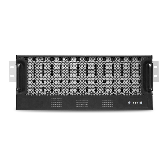
Chapter 1. Product Features 1�3 Features J4078-01 is a reliable SAS JBOD with 78 drives bays. This product is designed to accom- modate single/dual hub expanders with 4 Mini SAS HD wide ports. Featuring the expander chip, Broadcom SAS35x48, which is underscored for its high scalability and performance... - Page 14 J4078-01 User Manual Chapter 1. Product Features Front Panel J4078-01 offers 2 system buttons (System Power switch & System Alert Mute switch) and 4 LED indicators (Power, Power Fail, Temperature (overheating), and Fan Fault). System Power Temperature (Overheating) LED Behavior...
- Page 15 J4078-01 User Manual Chapter 1. Product Features Rear Panel 1600 W 1+1 redundant 80 + Platinum 4 x mini SAS HD 8 x 6056 fans NOTE The power supply only supports 200V~240V AC input...
- Page 16 J4078-01 User Manual Chapter 1. Product Features Rear Expander Panel J4078-01 offers single/dual expander(s) with 1 BMC port and 4 mini SAS HD ports per expander module. BMC LAN port 4 x mini SAS HD BMC console port & debug port...
- Page 17 J4078-01 User Manual Chapter 1. Product Features Major Components J4078-01 offers 3.5" x 78 HDD bays. • 12Gb/s & 6Gb/s SAS if using dual expanders • 12Gb/s SAS and 6Gb/s SATA if using single expander...
-
Page 18: Chapter 2� Hardware Setup
Chapter 2� Hardware Setup Chapter 2. Hardware Setup J4078-01 User Manual 2�1 Removing and Installing the Top Cover 2�1�1 Removing and Installing the First Top Cover Step 1 Push the release button on both sides of the top cover. Step 2 Lift the cover from the chassis. -
Page 19: Removing And Installing The Middle Top Cover
J4078-01 User Manual Chapter 2. Hardware Setup 2�1�2 Removing and Installing the Middle Top Cover Step 1 Push the release button on both sides of the top cover. Step 2 Lift the cover from the chassis. This information is provided for professional technicians only. -
Page 20: Removing And Installing Rear Top Cover
Chapter 2. Hardware Setup J4078-01 User Manual 2�1�3 Removing and Installing Rear Top Cover Step 1 Push the release button on both sides of the top cover. Step 2 Lift the cover from the chassis. This information is provided for professional technicians only. -
Page 21: 2�2 Removing And Installing The Hard Disk Drive
J4078-01 User Manual Chapter 2. Hardware Setup 2�2 Removing and Installing the Hard Disk Drive 2�2�1 Installing the 3�5" Hard Disk Drive Step 1 Match the dimples on the HDD with the tool-less tray. Step 2 Align the HDD with the tray by placing it against each other. -
Page 22: Removing The 3.5" Hdd From The Tray
Chapter 2. Hardware Setup J4078-01 User Manual Step 4 Complete the installation. 2�2�2 Removing the 3�5" HDD from the Tray Pull the sides of the tray to remove the HDD. Make certain to pull the tray with smaller dimples first away from the HDD and the larger dimples last for easier removal. -
Page 23: Installing The 2.5" Hard Disk Drive (Optional)
J4078-01 User Manual Chapter 2. Hardware Setup 2�2�3 Installing the 2�5" Hard Disk Drive (Optional) Step 1 Attach the HDD onto the HDD bracket and secure the screws (in red circle). Step 2 Match the dimples (in dotted red circle) on the HDD bracket and HDD with the tool-less tray. -
Page 24: Removing And Installing The Hdd Tray
Chapter 2. Hardware Setup J4078-01 User Manual 2�2�4 Removing and Installing the HDD Tray 2.2.4.1 Installing the HDD Tray Step 1 Insert the drive tray into chassis HDD cage. Make sure the drive tray is correctly secured in place when its front edge aligns with the bay edge. -
Page 25: 2�3 Removing And Installing The Power Supply Unit Module
J4078-01 User Manual Chapter 2. Hardware Setup 2�3 Removing and Installing the Power Supply Unit Module 2�3�1 Installing the Power Supply Unit Push the power supply module into the enclosure. Make sure the latch on the module is fully hooked onto the PSU housing. -
Page 26: 2�4 Removing And Installing The Fan Module
Chapter 2. Hardware Setup J4078-01 User Manual 2�4 Removing and Installing the Fan Module 2�4�1 Installing the Fan Align the fan module with the opening in the enclosure and insert the module into the JBOD. 2�4�2 Removing the Fan Step 1 Loosen the thumb screws x 2 pcs on the fan module. -
Page 27: 2�5 Removing And Installing The Expander Module
J4078-01 User Manual Chapter 2. Hardware Setup 2�5 Removing and Installing the Expander Module 2�5�1 Installing the Expander Step 1 Align the expander module with the opening in front of the enclosure and insert it into the enclosure. Step 2 Close the lever and secure the retaining screw. -
Page 28: 2�6 Removing And Installing The Hdd Backplane Module
Chapter 2. Hardware Setup J4078-01 User Manual 2�6 Removing and Installing the HDD Backplane Module NOTE Before you pull out the HDD backplane, your must remove all the HDD trays and cables. 2�6�1 Installing the HDD Backplane Step 1 Position the HDD backplane module into the chassis and secure the screws x 12 pcs onto the enclosure (8 screws on the HDD backplane, 4 screws on the HDD backplane tray). - Page 29 J4078-01 User Manual Chapter 2. Hardware Setup Bracket and HDD backplane removal Bracket and second HDD backplane removal This information is provided for professional technicians only.
-
Page 30: 2�7 Removing And Installing The Rear Handle
Chapter 2. Hardware Setup J4078-01 User Manual 2�7 Removing and Installing the Rear Handle 2�7�1 Installing the Rear Handle Step 1 Match the locking plate on the handle with the locks on the chassis. Step 2 Pull the handle upward to lock the handle onto the chassis. -
Page 31: 2�8 Slide Rail Installation
J4078-01 User Manual Chapter 2. Hardware Setup 2�8 Slide Rail Installation 1. Attach the slide rail braket assembly to the rack frame. Align and attach the front rail bracket to the rack. Ensure that the latch on the rail is hooked onto the rack. - Page 32 Chapter 2. Hardware Setup J4078-01 User Manual 2. Attach the chassis onto the rack fram Pull the inner and middle rail to fully locked position. Position the chassis vertically into the rail. Ensure the standoffs on the chassis ...
-
Page 33: Chapter 3 Sub-System Configuration Setup
AIC 12G Expander Controller To have multiple host/path access support (the host number can be up to the number of wide ports on each AIC 12G Expander Controller), only the following drives are supported for shared access: 1. SAS drive / Nearline SAS drive 2. -
Page 34: Chapter 4. Bmc Configuration Settings
Chapter 4. BMC Configuration Settings J4078-01 User Manual Chapter 4. BMC Configuration Settings 4�1 Login 1. Push the “[” key, it will show the IPMI serial interface. Type command for login the interface. #[sys pwd –u admin admin ] It will response [OK]... - Page 35 J4078-01 User Manual Chapter 4. BMC Configuration Settings 2. Find LAN information. Find LAN static IP /DHCP [30 00 02 01 04 00 00 ] Find LAN IP [30 00 02 01 03 00 00 ] Find submask [30 00 02 01 06 00 00 ]...
- Page 36 J4078-01 User Manual Chapter 4. BMC Configuration Settings 3. Set LAN information. Set LAN static IP /DHCP [30 00 01 01 04 01/02 ] Set LAN IP [30 00 01 01 03 C0 A8 00 0A ] Set submask [30 00 01 01 06 FF FF FF 00 ]...
- Page 37 J4078-01 User Manual Chapter 4. BMC Configuration Settings 4. Connect to RJ45 port. Set the local host IP to 192�168�11�xx segment. 5. Open the web browser and enter default IP http://192�168�11�11 . When the login window appears, set the user name and password to ''admin.'' 6.
-
Page 38: 4�2 Sensor's Location For Fan & Temperature
J4078-01 User Manual Chapter 4. BMC Configuration Settings 4�2 Sensor’s Location for Fan & Temperature EXP: expander chip fan 7 fan 5 fan 3 fan 1 Down fan 8 fan 6 fan 4 fan 2 (Up) (Up) Pri EXP Pri EXP... -
Page 39: 4�3 Expander Setting Via Java Sol
J4078-01 User Manual Chapter 4. BMC Configuration Settings 4�3 Expander Setting via Java Sol Step 1 Plug in the BMC LAN port. Expander rear panal Step 2 Log into the BMC interface. Please refer to Login. Step 3 Initiate Java SOL. Use one of the methods below to configure the expander setting. - Page 40 J4078-01 User Manual Chapter 4. BMC Configuration Settings 3. Check the warning message option and execute it (If JAVA blocks this action, please set the IP in order to access web site in the JAVA setting.).
- Page 41 J4078-01 User Manual Chapter 4. BMC Configuration Settings 4. Input the BMC IP, account, password, and set the baud rate to “38.4." 4U78swap: Hub 5. Now you can use the expander smart console via BMC SOL.
- Page 42 J4078-01 User Manual Chapter 4. BMC Configuration Settings Method 2 1. In addition, you can use ipmitool to start SOL function. #ipmitool –I lanplus –H <BMC IP> -U admin –P admin sol activate...
- Page 43 J4078-01 User Manual Chapter 4. BMC Configuration Settings 2. When you need to use SOL, type “~.” to exit this function. 3. If you want switch to another expander, you do not need to close SOL. Use the command below to switch your expander.
-
Page 44: Configure Serial Command Line Interface
J4078-01 User Manual Chapter 4. BMC Configuration Settings 4.3.2 Configure Serial Command Line Interface The RS232 setting - baud rate: 38400 bps, data bits: 8, parity: none, stop bits: 1, flow control: none 4.3.2.1 How to configure T10 zoning After enabling T10 zoning, five predefined groups are Group1, Group8, Group9, Group10, and Group11. -
Page 45: How To Get All Revisions In Aic Sas 12G Expander
J4078-01 User Manual Chapter 4. BMC Configuration Settings 4.3.2.2 How to get all revisions in AIC SAS 12G Expander ( A ) Expander firmware revision cmd> rev ( B ) Expander configuration revision cmd> showmfg ( C ) MCU firmware revision or sensor information (MCU firmware revision is reported by Hub only) cmd>... -
Page 46: How To Configure Wide Port Checker
This feature is applicable for SAS drives instead of SATA drives. If there is no connection with any active SAS initiator by checking all wide ports, AIC Expander Controller stops all attached SAS drives to save power consumption of SAS drives. -
Page 47: How To Configure Edfb (Edge Only)
J4078-01 User Manual Chapter 4. BMC Configuration Settings 4.3.2.7 How to configure EDFB (EDGE only) The default EDFB configuration is off. ( A ) Check the current configuration cmd> edfb EDFB is OFF ( B ) Enable the EDFB cmd>edfb on ( C ) Disable the EDFB cmd>... -
Page 48: How To Configure Zone Count
J4078-01 User Manual Chapter 4. BMC Configuration Settings 4.3.2.9 How to configure zone count Before you begin, your JBOD must be equipped with HUB/EDGE setting. There are 3 kinds of zoning options that can be implemented by Command Line interface operation. By using the zoning option, four of the 8644 ports will have a variety of zone group settings. - Page 49 J4078-01 User Manual Chapter 4. BMC Configuration Settings EDGE: Zone # Slot 1~39 40~78 (C-3) When Zone Count = 4, T10 zoning is enabled. HUB: Zone # Wideport EDGE: Zone # Slot 1~20 21~40 41~60 61~78...
- Page 50 J4078-01 User Manual Chapter 4. BMC Configuration Settings Zone Count Expander rear panel Zone count 1: 78 drives per zone. All SFF-8644 ports and drives are at the same zone group. SEE FIGURE BELOW. Group 1 Top View fan 1...
- Page 51 J4078-01 User Manual Chapter 4. BMC Configuration Settings Zone count 2: Expander rear panel 39 drives per zone. Port 1 & 2 is in zone group 1. Port 3 & 4 is in zone group 2. SEE FIGURE BELOW. Group 1...
- Page 52 J4078-01 User Manual Chapter 4. BMC Configuration Settings Zone count 4: 20 drives per zone. Port 1 is in at Expander rear panel zone group 1. Port 2 is in zone group 2. Port 3 is in zone group 3. Port 4 is at zone group 4.
-
Page 53: How To Configure Zoning Of The Wide Port (Hub Only)
J4078-01 User Manual Chapter 4. BMC Configuration Settings 4.3.2.10 How to configure zoning of the wide port (HUB only) After enabling T10 zoning, five predefined groups are Group1, Group8, Group9, Group10, and Group11. (A) Get current zoning of wide port 1 cmd>... -
Page 54: Ses Inband Features
Chapter 4. BMC Configuration Settings 4�3�3 SES Inband Features To ensure proper function, high performance, and durability, J4078-01 has implemented SCSI Enclosure Services to monitor the status of power supply, system cooling fan, and working temperature. It also has indicators to deliver the status of fail devices such as power supply or cooling fan. -
Page 55: Implementation On Ses
J4078-01 User Manual Chapter 4. BMC Configuration Settings 4.3.3.3 Implementation on SES Pages SES String In Page Get PMBUS information with String In Page. String In Format BYTE/BIT I2C congestion (0: no congestion, 1: congestion or failure) PSU Module1 STATUS_WORD... - Page 56 J4078-01 User Manual Chapter 4. BMC Configuration Settings SES Vendor specific page: Canister Number ( page code 83h) Out / In The length N of canister number can be 0~30 bytes. If no canister number is entered (N=0), then canister number is restored to default: 0x20 0x20 0x20 0x20 0x20 0x20 0x20 0x20 (8 spaces in ASCII).
-
Page 57: Implementation On Ses Elements
J4078-01 User Manual Chapter 4. BMC Configuration Settings 4.3.3.4 Implementation on SES Elements Only the fields highlighted in green are supported. Power Supply Element (A) Power Supply Control Element BYTE/BIT COMMON CONTROL SELECT PRDFAIL DISABLE Reserved SWAP RQST Reserved IDENT... - Page 58 J4078-01 User Manual Chapter 4. BMC Configuration Settings Cooling Element (A) Cooling Control Element BYTE/BIT COMMON CONTROL SELECT PRDFAIL DISABLE Reserved SWAP RQST Reserved IDENT RQST Reserved RQST ON Reserved REQUESTED SPEED CODE FAIL Field Value RQST IDENT Please refer to section “SES Element Control Functions” for details.
- Page 59 J4078-01 User Manual Chapter 4. BMC Configuration Settings Temperature Sensor Element (A) Temperature Sensor Control Element BYTE/BIT COMMON CONTROL SELECT PRDFAIL DISABLE Reserved SWAP RQST RQST Reserved IDENT FAIL Reserved Reserved (B) Temperature Sensor Status Element BYTE/BIT COMMON STATUS Reserved PRDFAIL DISABLE...
- Page 60 J4078-01 User Manual Chapter 4. BMC Configuration Settings Enclosure Element (A) Enclosure Control Element BYTE/BIT COMMON CONTROL SELECT PRDFAIL DISABLE Reserved SWAP RQST Reserved IDENT POWER CYCLE POWER CYCLE DELAY REQUEST REQUEST REQUEST POWER OFF DURATION FAILURE WARNING Field Value POWER CYCLE Please refer to section “SES Element Control Functions”...
- Page 61 J4078-01 User Manual Chapter 4. BMC Configuration Settings The time that power is scheduled to keep off when power is cycled. REQUEST 0: (i) No power cycle is scheduled or POWER OFF (ii) It is scheduled to be kept off for 10 seconds.
- Page 62 J4078-01 User Manual Chapter 4. BMC Configuration Settings Voltage Element (A) Voltage Control Element BYTE/BIT COMMON CONTROL SELECT PRDFAIL DISABLE Reserved SWAP RQST RQST Reserved IDENT FAIL Reserved Reserved (B) Voltage Status Element BYTE/BIT COMMON STATUS Reserved PRDFAIL DISABLE SWAP...
- Page 63 J4078-01 User Manual Chapter 4. BMC Configuration Settings Array Device Element (A) Array Device Control Element BYTE/BIT COMMON CONTROL SELECT PRDFAIL DISABLE Reserved0 SWAP RQST RQST RQST RQST RQST IN RQST RQST R/ RQST OK RSVD CONS IN CRIT FAILED...
- Page 64 J4078-01 User Manual Chapter 4. BMC Configuration Settings (B) Array Device Status Element BYTE/ COMMON STATUS Reserved PRDFAIL DISABLE SWAP ELEMENT STATUS CODE RSVD IN CRIT IN FAILED REBUILD/ DEVICE HOT SPARE CONS CHK R/R ABORT ARRAY ARRAY REMAP ENCLOSURE...
-
Page 65: Ses Element Control Functions
J4078-01 User Manual Chapter 4. BMC Configuration Settings 4.3.3.5 SES Element Control Functions LED indicators (blue and red) associated with an attached disk drive Array Device Slot control element BYTE/BIT COMMON CONTROL SELECT PRDFAIL DISABLE Reserved0 SWAP RQST RQST RQST... - Page 66 We use the software package "sg3_utils" on Linux for example, and have a SAS HBA and a cable to connect your host with the expander. (A) Show the device for AIC Expander Controller (canister) $ sg_map -i /dev/sg2 AIC 12G...
- Page 67 “PowerSupply01” to power off the entire enclosure. We use the software package "sg3_utils" on Linux for example, and have a SAS HBA and a cable to connect your host with the expander. (A) Show the device for AIC Expander Controller (canister) $ sg_map -i /dev/sg2 AIC...
- Page 68 “POWER CYCLE REQUEST” as 10b to cancel any scheduled power cycle. (A) Show the device for AIC Expander Controller (canister) $ sg_map -i /dev/sg2 AIC...
- Page 69 Clearing both bits disables the enclosure alarm. We use the software package "sg3_utils" on Linux for example, and have a SAS HBA and a cable to connect your host with the expander. (A) Show the device for AIC Expander Controller (canister) $ sg_map -i /dev/sg2 AIC 12G...
- Page 70 System fans) supports this feature. We use the software package "sg3_utils" on Linux for example, and have a SAS HBA and a cable to connect your host with the expander. (A) Show the device for AIC Expander Controller (canister) $ sg_map -i...
- Page 71 J4078-01 User Manual Chapter 4. BMC Configuration Settings REQUESTED SPEED CODE 100% Leave at current speed...
- Page 72 We use the software package "sg3_utils" and LSI utility “g3Xflash” on Linux for example, and have a SAS HBA and a cable to connect your host with the expander. (A) Show the device for AIC Expander Controller $ sg_map -i...
- Page 73 J4078-01 User Manual Chapter 4. BMC Configuration Settings (E) Show the devices for the Hub and the Edge0 $ sg_map -i /dev/sg1 AIC 12G 4U78swapHub 0c30 /dev/sg2 AIC 12G 4U78swapEdge0 0c31 (F) Update firmware of the Edge0 $ sg_write_buffer --id=0x0 --in=<firmware filename> --mode=0x2 --offset=0 /dev/ (G) Update MFG of the Edge0 $ sg_write_buffer --id=0x83 --in=<MFG filename>...
-
Page 74: Reading Phy Counters Via Java Sol
J4078-01 User Manual Chapter 4. BMC Configuration Settings 4�3�4 Reading Phy Counters via Java Sol 1. Initiate SOL function in BMC. #ipmitool –I lanplus –H [BMC_IP] –U admin –P admin sol activate 2. Select expander connection NetFN 36 Command Code: 53h... - Page 75 J4078-01 User Manual Chapter 4. BMC Configuration Settings 4. Type in “counters” to execute counters command.
- Page 76 J4078-01 User Manual Chapter 4. BMC Configuration Settings 5. To read the the expander Edge-1 counter value, 1, execute the ipmi command to configure BMC SOL to Edge-1 # ipmitool -I lanplus -H [BMC_IP] -U admin -P admin raw 0x36 0x54 0x3...
- Page 77 J4078-01 User Manual Chapter 4. BMC Configuration Settings 6. Type in “counters” to execute counters command.
-
Page 78: 4�4 Web
J4078-01 User Manual Chapter 4. BMC Configuration Settings 4�4 Web UI 4�4�1 Dashboard Device Information Displays the Firmware Revision and Firmware Build Time (Date and Time). Network Information Shows network settings for the device. Click on the link Edit to view the Network Settings Page. -
Page 79: Fru Information
J4078-01 User Manual Chapter 4. BMC Configuration Settings 4�4�2 FRU information This page displays the BMC FRU file information. On selecting a particular FRU Device ID its corresponding FRU information will be displayed. Basic Information It displays the FRU device ID and device name for the selected FRU device ID. -
Page 80: Hard Disk Status
J4078-01 User Manual Chapter 4. BMC Configuration Settings 4�4�3 Hard Disk Status This page displays all the HDD power on/off status, user the "Power On" and "Power Off" button to control HDD power. ACTIONS Power On Select a HDD to turn it power on. -
Page 81: Storage Heath
J4078-01 User Manual Chapter 4. BMC Configuration Settings 4�4�4 Storage Heath 4.4.4.1 Sensor Readings A list of sensor readings will be displayed here. Click on a record to show more information about that particular sensor, including thresholds and a graphical representation of all associated events. -
Page 82: Event Log
J4078-01 User Manual Chapter 4. BMC Configuration Settings 4.4.4.2 Event Log This page displays the list of events incurred by different sensors on this device. Double click on a record to see the details of that entry. You can also sort the list of entries by clicking on any of the column headers. -
Page 83: Configuration
J4078-01 User Manual Chapter 4. BMC Configuration Settings 4.4.5 Configuration 4.4.5.1 DNS This page is used to configure the Host name and Domain Name Server configuration of the device. Host configuration Host Settings Choose either Automatic or Manual settings. Host Name It displays the hostname of the device if Auto is selected. - Page 84 J4078-01 User Manual Chapter 4. BMC Configuration Settings Domain Name It displays the domain name of the device if Auto is selected. If the Domain setting is chosen as Manual, then specify the domain name of the device. Domain Name Server Configuration DNS Server Settings It lists the options for the DNS interface, Manual and available LAN interfaces.
-
Page 85: Network Settings
J4078-01 User Manual Chapter 4. BMC Configuration Settings 4.4.5.2 Network Settings This page is used to configure the network settings for available LAN channels. LAN Interface Select the LAN interface to be configured. LAN Settings Check this option to enable LAN support for the selected interface. - Page 86 J4078-01 User Manual Chapter 4. BMC Configuration Settings IPv6 Configuration It lists the IPv6 configuration settings. IPv6 Settings Check this option to enable IPv6 support for the selected interface. Obtain an IP address automatically Enable ‘Use DHCP’ to dynamically configure the IPv4 address using Dynamic Host Configuration Protocol (DHCP).
-
Page 87: Network Link
J4078-01 User Manual Chapter 4. BMC Configuration Settings 4.4.5.3 Network Link This page is used to configure the network link option for the available network interfaces. LAN Interface Select the network interface from the list for which the Link speed and duplex mode are to be configured. -
Page 88: Ntp
J4078-01 User Manual Chapter 4. BMC Configuration Settings 4.4.5.4 NTP This page displays the device’s current Date & Time Settings. It can be used to configure either Date & Time or NTP (Network Time Protocol) server settings for the device. - Page 89 J4078-01 User Manual Chapter 4. BMC Configuration Settings Automatically synchronize Check this option to automatically synchronize Date and Time with the NTP Server. Refresh Click ‘Refresh’ to reload the current date & time settings. Save Click ‘Save’ to save any changes made.
-
Page 90: Pef
J4078-01 User Manual Chapter 4. BMC Configuration Settings 4.4.5.5 PEF This page is used to configure the Event Filter, Alert Policy and LAN Destination. To view the page, the user must at least be an Operator. To modify or add a PEF, the user must be an Administrator. - Page 91 J4078-01 User Manual Chapter 4. BMC Configuration Settings NOTE: Test alerts can be sent only with SMTP configurations set to enabled. SMTP suppport can be enabled under Configuration->SMTP. Select a free slot and click ‘Add’ to add a new entry to the device. Alternatively, double click on a free slot.
-
Page 92: Smtp
J4078-01 User Manual Chapter 4. BMC Configuration Settings 4.4.5.6 SMTP This page is used to configure the SMTP settings. LAN Channel Number Select the LAN channel to which the SMTP information needs to be configured. Sender Address Enter the ‘Sender Address’ valid on the SMTP Server. - Page 93 J4078-01 User Manual Chapter 4. BMC Configuration Settings The server address will support the following: • IPv4 Address format. • IPv6 Address format. SMTP Server requires Authentication Check the option ‘Enable’ to enable SMTP Authentication. Note: SMTP Server Authentication Types supported are: •...
-
Page 94: Schedule Power On/Off
J4078-01 User Manual Chapter 4. BMC Configuration Settings 4.4.5.7 Schedule Power ON/OFF This page displays the device's current date & time. It can be used to configure dates within a week or specific a date to power on/off the device. - Page 95 J4078-01 User Manual Chapter 4. BMC Configuration Settings ACTIONS Enable schedule Check this option for enable/disable the schedule. Action Check a action to do power on/off for the device. Set days for action Setting dates within a week to do power on/off for the device.
-
Page 96: User
J4078-01 User Manual Chapter 4. BMC Configuration Settings 4.4.5.8 User The displayed table shows any configured Users and available slots. You can modify or add new users from here. A maximum of 10 slots are available, including the default admin and anonymous. It is advised that the anonymous user’s privilege and password should be modified as a security measure. -
Page 97: Remote Control
J4078-01 User Manual Chapter 4. BMC Configuration Settings 4�4�6 Remote Control 4.4.6.1 Storage power control This page helps you to view or perform any host power cycle operations. Power Off Storage Select this option to immediately power off the storage. -
Page 98: Zone Settings
J4078-01 User Manual Chapter 4. BMC Configuration Settings 4.4.6.2 Zone Settings You can setup and check the zone count setting in this page. Set zone value You can set a zone count value and click the SET button. The BMC will be configured on all of the hub and edge expander. - Page 99 J4078-01 User Manual Chapter 4. BMC Configuration Settings GET ZONE COUNT NetFN 36 Command Code: 52h Message Byte Data Field Expander select 01h: Hub Request 02h: Edge_0 03h: Edge_1 04h: Edge_2 Completion Code Response 00h Success zone count value #ipmitool –I lanplus –H <BMC IP> -U admin –P admin raw 0x36 0x52 0x1...
-
Page 100: 4�5 Bmc Firmware Update
J4078-01 User Manual Chapter 4. BMC Configuration Settings 4�5 BMC Firmware Update 4�5�1 Requirement Browsers: FireFox 24.0 or later version Chrome 35.0 or later version I.E. 7.0 or later version Linux: Redhat 6.4 If you want to update a new version firmware for BMC, when finished all the update process, please clear the web browser cookies�... - Page 101 J4078-01 User Manual Chapter 4. BMC Configuration Settings 3. This is login main page. 4. Click the “Firmware Update” and it will pop a drop-down menu. Click “Firmware Update.”...
- Page 102 J4078-01 User Manual Chapter 4. BMC Configuration Settings 5. This page shows the update warning. If you want to update the BMC firmware, click the “Enter Update Mode” button. 6. Wait a few minutes and a window will pop up. Click “Select file” to upload the...
- Page 103 J4078-01 User Manual Chapter 4. BMC Configuration Settings 7. Wait a few minutes and the window that checks the update section will pop up. Check the “Check this option to do all full firmware flash” option. 8. Click “OK” and the firmware will start the update process.
- Page 104 J4078-01 User Manual Chapter 4. BMC Configuration Settings 9. In the update process, it will take 3~5 minutes. Caution: Please do not close this webpage! Closing the web page may cause the firmware to crash. 10. When “Device has been reset” window appears, it means the firmware...
-
Page 105: Image Transfer Protocol
J4078-01 User Manual Chapter 4. BMC Configuration Settings 4�5�3 Image Transfer Protocol This page is used to configure the firmware image protocol information. ACTIONS Protocol Type Protocol to be used to transfer the firmware image into the BMC. Server Address Address of the server where the firmware image is stored. -
Page 106: 4�6 Expander Firmware/Mfg Update
J4078-01 User Manual Chapter 4. BMC Configuration Settings 4�6 Expander Firmware/MFG Update 1. Click Firmware Update > Expander Firmware Update in your BMC menu bar. 2. Under "Select the expander," choose an expander and click Start update. - Page 107 J4078-01 User Manual Chapter 4. BMC Configuration Settings 3. Click Choose File. 4. Select and click Open.
- Page 108 J4078-01 User Manual Chapter 4. BMC Configuration Settings 5. Click Upload� 6. Click Proceed.
- Page 109 J4078-01 User Manual Chapter 4. BMC Configuration Settings 7. Wait a few seconds. 8. Click Choose File�...
- Page 110 J4078-01 User Manual Chapter 4. BMC Configuration Settings 9. Choose .bin and click Upload. 10. Click Proceed.
- Page 111 J4078-01 User Manual Chapter 4. BMC Configuration Settings 11. Update complete. 12. To select another expander, please refer to steps 2 to 11.
-
Page 112: Chapter 5� Technical Support
Chapter 5� Technical Support Taiwain, Global Headquarters South California, United States Address: No� 152, Section 4, Address: 21808 Garcia Lane Linghang N� Rd, Dayuan District, City of Industry, CA 91789, Taoyuan City 337, Taiwan United States Tel: +886-3-433-9188 Toll free: +7-4997019998 Fax: +886-3-287-1818 Tel: +1-909-895-8989 Sales Email: sales@aicipc�com�tw...
Need help?
Do you have a question about the J4078-01 and is the answer not in the manual?
Questions and answers