Table of Contents
Advertisement
Quick Links
Advertisement
Table of Contents

Related Manuals for AIC FB201-LX


Summary of Contents for AIC FB201-LX
- Page 1 FB201-LX Server Barebone User's Manual UM_FB201-LX_v1.1_022119...
-
Page 2: Table Of Contents
Table of Contents Preface ������������������������������������������������������������������������������������������������� i Safety Instructions ������������������������������������������������������������������������������ ii About This Manual ������������������������������������������������������������������������������ iv Chapter 1� Product Features �������������������������������������������������������������� 1 1�1 Box Contents �����������������������������������������������������������������������������������1 1.2 Specifications �����������������������������������������������������������������������������������2 1�3 Feature ���������������������������������������������������������������������������������������������3 Chapter 2� Hardware Setup ���������������������������������������������������������������� 8 2�1 Central Processing Unit Setup ����������������������������������������������������������8 2.1.1 Processor Installation ..................8 2�2 System Memory Setup ��������������������������������������������������������������������11 2.2.1 DIMM Installation .................... - Page 3 2.9.2 Installing the Riser Card .................. 22 2�10 Tool-less Slide Blade Installation ��������������������������������������������������23 Chapter 3� Hardware Settings ���������������������������������������������������������� 27 3�1 Motherboard Block Diagram ������������������������������������������������������������27 3�2 Motherboard Content List ���������������������������������������������������������������28 3�3 Motherboard Layout ������������������������������������������������������������������������30 3�4 Connector and Jumper ��������������������������������������������������������������������31 3�5 System LED Indicator ����������������������������������������������������������������������40 3.5.1 Front Panel LED ....................
- Page 4 4.4.13 APEI Configuration ..................72 4.4.14 Console Redirection Setup ................73 4�5 Security ������������������������������������������������������������������������������������������74 4.5.1 Security ......................74 4�6 Power ���������������������������������������������������������������������������������������������75 4.6.1 Power ....................... 75 4�7 Boot ������������������������������������������������������������������������������������������������76 4.7.1 Boot ........................76 4�8 Exit �������������������������������������������������������������������������������������������������77 4.8.1 Exit ........................77 Chapter 5. BMC Configuration Settings �������������������������������������������� 78 5�1 Login ����������������������������������������������������������������������������������������������78 5�2 Web GUI ����������������������������������������������������������������������������������������79 5.2.1 Menu Bar ......................
- Page 5 Document Release History Release Date Version Update Content January User's Manual release to public. 2019 Febuary Safety information update. 2019 Contents...
- Page 6 Copyright © 2019 AIC, Inc� All Rights Reserved� This document contains proprietary information about AIC products and is not to be disclosed or used except in accordance with applicable agreements.
-
Page 7: Preface
Disclaimer AIC shall not be liable for technical or editorial errors or omissions contained herein. The information provided is provided "as is" without warranty of any kind. To the extent permitted by law, neither AIC or its affiliates, subcontractors or suppliers will be liable for incidental, special or consequential damages including downtime cost;... -
Page 8: Safety Instructions
Safety Instructions Before getting started, please read the following important cautions: • All cautions and warnings on the equipment or in the manuals should be noted. • Most electronic components are sensitive to electrical static discharge. Therefore, be sure to ground yourself at all times when installing the internal components. •... - Page 9 • If the equipment is not used for a long time, disconnect the equipment from mains to avoid being damaged by transient over-voltage. • Never open the equipment. For safety reasons, only qualified service personnel should open the equipment. • If one of the following situations arise, the equipment should be checked by service personnel: 1.
-
Page 10: About This Manual
This document pellucidly presents a brief overview of the product design, device installation, and firmware settings for FB201-LX. For the latest version of this user's manual, please refer to the AIC website: http://www.aicipc.com/tw/productdetail/51014. -
Page 11: Chapter 1� Product Features
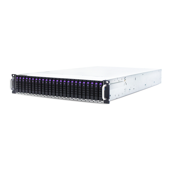
Chapter 1. Product Features FB201-LX User Manual Chapter 1. Product Features FB201-LX is a high density storage server that includes mother board, chassis, redundant power supplies, HDD backplane, and hotswapple fans. For more information about our product, please visit our website at http://www.aicipc.com/en. -
Page 12: 1.2 Specifications
FB201-LX User Manual Chapter 1. Product Features 1.2 Specifications Riser Card mm : 438 x 800 x 88 Dimensions RC-PE2U09-TY 2 x16 PCIe slots (included) (W x D x H) inches : 17.2 x 31.5 x 3.5 AIC Server Board Lynx... -
Page 13: 1�3 Feature
Chapter 1. Product Features 1�3 Feature FB201-LX is a reliable 2U storage server barebone with 24 hotswap drives bays at the front and 2 hotswap drive bays at the rear. This product is designed to accommodate the AIC-patented serverboard, Lynx, which supports two Intel® Xeon® Scalable Processors and 24 DDR4 DIMM to offer greater perfomance, efficiency, and utility for our customers. - Page 14 FB201-LX User Manual Chapter 1. Product Features Front Panel 2.5" HDD hotwap drive (U.2 NVMe) Power On/Off Button System Power LED System HDD Activity LED LAN LED System Alert LED System ID LED System ID Button System Reset Button...
- Page 15 FB201-LX User Manual Chapter 1. Product Features Rear Panel 2.5" HDD tray low profile PCIe RJ45 dedicated to BMC VGA port RJ45 USB 3.0 Type A 1600W 1+1 redundant PSU port Rear Panel without 2�5" Tray RJ45 dedicated to BMC...
- Page 16 FB201-LX User Manual Chapter 1. Product Features Top view 1600W 1+1 redundant power supply 80+ Platinum 4 x 60 x 56mm hotswap fans...
- Page 17 FB201-LX User Manual Chapter 1. Product Features System Block Diagram Code Name : MB-DPSK03 LYNX MB BLOCK DIAGRAM LYNX MB BLOCK DIAGRAM Project Name : Lynx Lynx : Review Project Code : B48-DTIET02G00A000 CPU Footprint(LGA3647-P0 NRW-F) Version : A Platform Environment Control Interface(PECI)
-
Page 18: Chapter 2� Hardware Setup
Chapter 2� Hardware Setup Chapter 2. Hardware Setup FB201-LX User Manual This section describes a simple instruction guide for installing the hardware components on the serverboard system. Turn off and unplug all system and peripheral devices before proceeding. 2�1 Central Processing Unit Setup The serverboard supports dual Xeon scalable processors and Socket P0 (LGA-3647). - Page 19 FB201-LX User Manual Chapter 2. Hardware Setup Processor Socker Assembly: The server board includes two processor sockets (LGA-3647), supports two Intel® Xeon® Processor Scalable Family and has a Thermal Design Power (TDP) of up to 165W on selected models. PHM (Processor Heatsink Module) Component:...
- Page 20 Chapter 2. Hardware Setup FB201-LX User Manual PHM Screw Installation Order: The PHM sits level with the processor socket assembly. The PHM is NOT installed properly if it does not sit level with the processor socket assembly. Once the PHM is seated over the processor socket assembly, the four heat sink torque screws must be secured in the following order as shown below.
-
Page 21: 2�2 System Memory Setup
FB201-LX User Manual Chapter 2. Hardware Setup 2�2 System Memory Setup This server board supports 24 DDR4 2400/2666 Registered ECC SDRAM(RDIMM) / Load- Reduced DIMM (LRDIMM). 2�2�1 DIMM Installation Step 1 Unlock the dimm socket by pressing the retaining clips outward. -
Page 22: Dimm Location
Chapter 2. Hardware Setup FB201-LX User Manual 2�2�2 DIMM Location CPU1 JDIMMJ1 JDIMMJ0 JDIMMK1 JDIMMK0 JDIMML1 JDIMML0 JDIMMC0 JDIMMC1 JDIMMB0 JDIMMB1 JDIMMA0 JDIMMA1 CPU0 JDIMMD1 JDIMMD0 JDIMME1 JDIMME0 JDIMMF1 JDIMMF0... -
Page 23: Dimm Slot Installation Order
FB201-LX User Manual Chapter 2. Hardware Setup 2�2�3 DIMM Slot installation Order DIMM DIMM Numbers Placement Numbers CPU1 CPU0 JDIMMI1 JDIMMC1 JDIMMH0 JDIMMB0 JDIMMH1 JDIMMB1 JDIMMG0 JDIMMA0 JDIMMG1 JDIMMA1 2 DIMMs JDIMM_I0 JDIMM_C0 CPU1 CPU1 CPU0 CPU0 JDIMMD1 JDIMMJ1 JDIMMD0... - Page 24 Chapter 2. Hardware Setup FB201-LX User Manual CPU1 CPU0 JDIMMI1 JDIMMC1 JDIMM_I0 JDIMM_C0 JDIMMH1 JDIMMB1 JDIMMG1 JDIMMA1 JDIMM_H0 JDIMM_B0 10 DIMMs CPU1 CPU1 CPU0 CPU0 JDIMM_G0 JDIMM_A0 JDIMM_K0 JDIMM_E0 JDIMMJ1 JDIMMD1 JDIMMJ0 JDIMMD0 JDIMMK1 JDIMME1 JDIMM_L0 JDIMM_F0 JDIMMF1 JDIMML1 CPU1...
- Page 25 FB201-LX User Manual Chapter 2. Hardware Setup CPU1 CPU0 JDIMM_I0 JDIMM_C0 JDIMM_I1 JDIMM_C1 JDIMM_H0 JDIMM_B0 JDIMM_H1 JDIMM_B1 20 DIMMs JDIMM_G0 JDIMM_A0 CPU1 CPU1 CPU0 CPU0 JDIMM_G1 JDIMM_A1 JDIMM_J0 JDIMM_D0 JDIMMD1 JDIMMJ1 JDIMM_K0 JDIMM_E0 JDIMME1 JDIMMK1 JDIMM_L1 JDIMM_F1 JDIMM_L0 JDIMM_F0 CPU1...
-
Page 26: 2�3 Removing And Installing The Top Cover
Chapter 2. Hardware Setup FB201-LX User Manual 2�3 Removing and Installing the Top Cover 2�3�1 Removing the Top Cover Step 1 Press the release button x 2 on both sides of the system. Step 2 Slide the cover toward the rear panel and pull upward to remove. -
Page 27: 2�4 Removing And Installing Power Supply Unit Module
FB201-LX User Manual Chapter 2. Hardware Setup 2�4 Removing and Installing Power Supply Unit Module 2�4�1 Removing the Power Supply Unit Step 1 Press the latch and hold the handle on the module. Step 2 Pull the module out of the system barebone. -
Page 28: 2�5 Removing And Installing Fan Module
Chapter 2. Hardware Setup FB201-LX User Manual 2�5 Removing and Installing Fan Module 2�5�1 Removing the Fan Pull to remove the fan module from the system. 2�5�2 Installing the Fan Insert the fan module into the fan slot. Verify if the fan is properly aligned with the... -
Page 29: 2�6 Removing And Installing Hard Disk Drive
FB201-LX User Manual Chapter 2. Hardware Setup 2�6 Removing and Installing Hard Disk Drive 2�6�1 Removing the Hard Disk Drive Tray Step 1 Press the release button the tray lever to loosen the lever. Step 2 Pull the tray lever outward completetly to remove the tray. -
Page 30: 2�7 Removing And Installing The Hdd Backplane
Chapter 2. Hardware Setup FB201-LX User Manual 2�7 Removing and Installing the HDD Backplane 2�7�1 Removing the HDD Backplane Step 1 Detach the cables & HDDs from the backplane and the release the backplane by shifting the hook. Step 2 Dislodge the screws on the backplane and lift the blackplane upward to remove. -
Page 31: 2�8 Removing And Installing The Bridge Board
FB201-LX User Manual Chapter 2. Hardware Setup 2�8 Removing and Installing the Bridge Board 2�8�1 Removing the Bridge Board Step 1 Loosen the captive screws x 2. Step 2 Pull the bridge board upward to remove. 2�8�2 Installing the Bridge Board Step 1 Align and insert the bridge board with the bracket into the appropriate card slot. -
Page 32: 2�9 Removing And Installing The Riser Card
Chapter 2. Hardware Setup FB201-LX User Manual 2�9 Removing and Installing the Riser Card 2�9�1 Removing the Riser Card Step 1 Loosen the captive screw. Step 2 Remove the riser card from the system. 2�9�2 Installing the Riser Card Step 1 Align and insert the riser card with bracket into the appropriate card slot. -
Page 33: 2�10 Tool-Less Slide Blade Installation
FB201-LX User Manual Chapter 2. Hardware Setup 2�10 Tool-less Slide Blade Installation 1. Pull on the ‘’Front-Release’’to unlock the inner channel from the Slide Assembly. 2. Release the Detent-Lock and push Middle Channel inwards to retract Middle Channel. - Page 34 Chapter 2. Hardware Setup FB201-LX User Manual Optional: Remove Metal Spacer for Aluminium Racks Metal Spacer 3. Aligning the Front Bracket with the Mounting Hole. 4. Push in to assembly the Front Bracket onto the Rack.
- Page 35 FB201-LX User Manual Chapter 2. Hardware Setup 5. Now the bracket is fixed onto the Rack. (Optional M6x10L screws are to secure the rails with posts if needed.) 6. Refer to step 3 and 4 to assemble the End Bracket onto the Rack.
- Page 36 Chapter 2. Hardware Setup FB201-LX User Manual 7. Assemble the inner channel onto the chassis using thescrews provided. 8. Push the chassis with inner channels into Slide to complete Rack Installation.
-
Page 37: Chapter 3� Hardware Settings
Chapter 3� Hardware Settings FB201-LX User Manual Chapter 3. Motherboard Settings This section provides illustrations that display the internal jumpers, connectors, and system LED indicators. 3�1 Motherboard Block Diagram Platform Environment Control Interface(PECI) USB2#9 DIMM #I1 DIMM #C1 USB2#8 USB2.0(X2) -
Page 38: 3�2 Motherboard Content List
FB201-LX User Manual Chapter 3. Motherboard Settings Connector/Header/Jumper Location Connector/Header/Jumper Location 3�2 Motherboard Content List Power Supply COM CPU0 Configurations J15, J16 JPG_LOCK Bus Disable Jumper Jumper Power Supply PSKILL J14, J17 COM Port JCOM1, JCOM4 Disable Jumper Backplane Power... - Page 39 FB201-LX User Manual Chapter 3. Motherboard Settings Connector/Header/Jumper Location Connector/Header/Jumper Location No Reboot (Watch 51 VROC Key Header JRAID_KEY dog) Jumper BIOS Recovery Mode ME Force Recovery Jumper Mode Jumper JNGFF1, JNGFF Connector 53 Speaker JSPKR JNGFF2 AUX Power Header...
-
Page 40: 3�3 Motherboard Layout
FB201-LX User Manual Chapter 3. Motherboard Settings 3�3 Motherboard Layout 29b 30b 54 55 56 57 CPU1 JDIMMJ1 JDIMMJ 0 JDIMMK0 JDIMML1 JDIMML0 JDIMMC0 JDIMMC1 JDIMMB0 SATA6 JDIMMB1 JDIMMA0 SATA5 JDIMMA1 24 DIMM Sockets SATA4 SATA10 SATA3 SATA9 SATA2 SATA8... -
Page 41: 3�4 Connector And Jumper
FB201-LX User Manual Chapter 3. Motherboard Settings 3�4 Connector and Jumper 3a Backplane Power Header (JPWR1) 3b Backplane Power Header (JPWR2) 3c Backplane Power Header (JPWR3) 3d Backplane Power Header (JPWR4) 4 Power Supply Connector (JPWR5) 6 Power Supply Header (JPMBUS_PDB) - Page 42 FB201-LX User Manual Chapter 3. Motherboard Settings 8a Fan Connector (J19) 8e Fan Connector (J26) 8b Fan Connector (J20) 8f Fan Connector (J27) 8c Fan Connector (J23) 8g Fan Connector (J28) 8d Fan Connector (J25) +12V TACH FAN_PRSNT_N LED_FAN_FAULT 9a Power Supply Connector: 12V (JPWR6)
- Page 43 FB201-LX User Manual Chapter 3. Motherboard Settings 14 Front I/O USB 2.0 Header (JUSB20) 15 OCulink Connector (JSYS_EXT) BMC GPIO Header (JBMC_GPIO1) BMC GPIO Header (JBMC_GPIO2) GPIOP3 GPIOP2 GPIOI3 GPION7 +3.3V_DUAL...
- Page 44 FB201-LX User Manual Chapter 3. Motherboard Settings 17 Front Panel Header ( JFRNT_SSI PCH SGPIO Header (JSGPIO) 20 PCH SSGPIO (JSSGPIO)
- Page 45 FB201-LX User Manual Chapter 3. Motherboard Settings COM Port (JCOM1) COM Port (JCOM4) 23 BMC Debug Port Header (JBMC_DP) BMC_UART_TXD5 BMC_UART_RXD5 24 Buzzer Header (JBUZZER) BMC_BUZZER- 25 LCM Header (JLCM) SW_PWR_BTN# SW_RST_BTN# TXDC RXDC HFI Header (JHFI1/JHFI2) SMB_HFI0CPU0_LVC2_SCL FM_MODPRST_HFI0_CPU0_LVT2_N SMB_HFI0CPU0_LVC2_SDA...
- Page 46 FB201-LX User Manual Chapter 3. Motherboard Settings HFI Header (JHFI2) SMB_HFI0CPU1_LVC2_SCL FM_MODPRST_HFI0_CPU1_LVT2_N SMB_HFI0CPU1_LVC2_SDA LED_HFI0_CPU1_N RST_HFI0_CPU1_LVT2_N IRQ_HFI0_CPU1_LVT2_N SMB_HFI1CPU1_LVC2_SCL FM_MODPRST_HFI1_CPU1_LVT2_N SMB_HFI1CPU1_LVC2_SDA LED_HFI1_CPU1_N RST_HFI1_CPU1_LVT2_N IRQ_HFI1_CPU1_LVT2_N +12V +3.3V PVPP_GHI_GD +3.3V PVPP_GHI SMB_3V3SB_CLK SMB_3V3SB_DAT 33 IPMB Header (JBMC_I2C1) I2C1SDA I2C1SCL N.C. 39 BMC I2C10 Header (JBMC_I2C10)
- Page 47 FB201-LX User Manual Chapter 3. Motherboard Settings 45 VGA Header (JVGA_INT) DACROA N.C. DACGOA DDC_DATAO DACBOA AHSYNCO N.C. DVO_5V AVSYNCO DDC_CLKO 46 SATA DOM Power Header (JDOM_PWR) +12V 47 VRM SMB Header (JSMB_VR) SMB_VR_DAT SMB_VR_CLK 51 VROC KEY BOX Header (JRAID_KEY) +3.3V_DUAL...
- Page 48 FB201-LX User Manual Chapter 3. Motherboard Settings 58 PCIE Hot-Plug SMB Header (JPCIE_HP) CPU1_HP_I2C_CLK CPU0_HP_I2C_CLK CPU1_HP_I2C_DAT CPU10_HP_I2C_DAT +3.3V Power Supply Connector (J9) Power Supply Connector (J10) +12V +12V +12V +12V +12V +12V +12V +12V +12V +12V +12V +12V +12V +12V...
- Page 49 FB201-LX User Manual Chapter 3. Motherboard Settings 34 BMC Disable Jumper (JBMC_DIS) BMC Disable Jump Setting JBMC_DIS Setting Short Disable (Default) Open Normal 35 BMC Reset Jumper (JBMC_RST) BMC Reset Jump Setting JBMC_RST Setting Short Reset BMC (Default) Open Normal...
-
Page 50: 3�5 System Led Indicator
FB201-LX User Manual Chapter 3. Motherboard Settings 3�5 System LED Indicator 3�5�1 Front Panel LED Green System is on. Power Status System is off. Yellow (Blinking) Disk activity is detected. HDD Drive Activity No disk activity is detected. Yellow (Blinking) -
Page 51: Internal Led
FB201-LX User Manual Chapter 3. Motherboard Settings 3�5�2 Internal LED JDIMMJ0 JDIMMK1 NGFF2 ACT LED JDIMML0 JDIMMC0 JDIMMC1 NGFF1 ACT LED JDIMMB0 JDIMMB1 UID LED UID LED JDIMMA1 RSMRST PG LED RSMRST PG LED SYSTEM PG LED SYSTEM PG LED... -
Page 52: 3�6 Hdd Backplane
FB201-LX User Manual Chapter 3. Motherboard Settings 3�6 HDD Backplane 3�6�1 Layout Top View Bottom View... -
Page 53: Connector And Jumper
FB201-LX User Manual Chapter 3. Motherboard Settings 3�6�2 Connector and Jumper Connector Function Physical Description Location SFF8639 Connector NVME SSD connector J2000 ~ J2011 Connect with Bridge board pin define AirMax Connector J1 ~ J6 by AIC. 12V power input connector with Bridge... -
Page 54: Chapter 4. Bios Configuration Settings
Chapter 4. BIOS Configuration Settings FB201-LX User Manual Chapter 4. BIOS Configuration Settings This chapter demonstrates how to configure the UEFI BIOS settings in your system device. You can enter the BIOS screen during system startup. To enter BIOS configuration settings, •... -
Page 55: 4�2 Bios Menu
FB201-LX User Manual Chapter 4. BIOS Configuration Settings 4�2 BIOS Menu 4�2�1 Menu Press and to select the options of the menu bar. Press Enter to access the option screen. Menu Description Displays system information such as CPU bus... - Page 56 FB201-LX User Manual Chapter 4. BIOS Configuration Settings Step 2 There will be a message “Entering SETUP” displayed on the diagnostics screen. Step 3 Identify the BIOS version. CAUTION For the official released version, the last digit of the BIOS version must end in a “0.“...
- Page 57 FB201-LX User Manual Chapter 4. BIOS Configuration Settings Step 4 Load Optimal Default Setting. Step 5 Save the setting and exit the BIOS setup utility.
-
Page 58: 4�3 Main
FB201-LX User Manual Chapter 4. BIOS Configuration Settings 4�3 Main Main Option Key: 4�3�1 Main Option Key Description System time Configures the current time. System date Configures the current date. -
Page 59: 4�4 Advanced
FB201-LX User Manual Chapter 4. BIOS Configuration Settings 4�4 Advanced Advanced Option Key: 4.4.1 Boot Configuration Boot Configuration Numlock SCU Resolution 640*480 800*600 1024*768 Auto CSM on Enable Disable Demand USB BIOS Support USB BIOS Enable Disable UEFI Only Support... -
Page 60: 4.4.2 Peripheral Configuration
FB201-LX User Manual Chapter 4. BIOS Configuration Settings 4.4.2 Peripheral Configuration Peripheral Configuration PCIe SR-IOV Enable Disable PCIe ARI Enable Disable ARI Forward Enable Disable Spread Enable Disable Spectrum 4.4.3 Video Configuration Video Configuration Display Mode Plug In First On Board First 4�4�4 ACPI Table/Features Control... - Page 61 FB201-LX User Manual Chapter 4. BIOS Configuration Settings EMCA MCE-SMI EMCA gen 1 Dual EMCA gen 2 - Disable Enable Mode MSMI Corrected Error eLog Enable Disable eMCA Settings Memory Error eLog Enable Disable Processor Error eLog Enable Disable WHEA Support...
- Page 62 FB201-LX User Manual Chapter 4. BIOS Configuration Settings IIO/PCH Global Error Enable Disable Support IIO MCA Support Enable Disable IIO Error Pin Programming Enable Disable IIO Error Registers Clear Enable Disable IIO LER Support Enable Disable LER MA Error Logging...
-
Page 63: Debug Configuration
FB201-LX User Manual Chapter 4. BIOS Configuration Settings PCIE AER Corrected Enable Disable Errors PCIE AER Advisory Enable Disable Nonfatal Error PCIE AER Nonfatal Error Enable Disable PCIe Error PCIE AER Fatal Error Enable Disable Enabling SERR Propagation Enable Disable... -
Page 64: Socket Configuration
FB201-LX User Manual Chapter 4. BIOS Configuration Settings Serial Port D Auto Enable Disable Base I/O Address Interrupt IRQ7 IRQ10 4�4�9 Socket Configuration Socket Configuration Hyper-Threading Enable Disable [ALL] Check CPU BIST Enable Disable Result 3StrikeTimer Enable Disable Fast String... - Page 65 FB201-LX User Manual Chapter 4. BIOS Configuration Settings Core Disable Min=0x0, Max=0xfffffff Bitmap(Hex) CPU Socket IOT Cfg Enable Disable Processor 0/1/2/3 Configuration Num of OCLA Configuration Min=0, Max=8 Ways OCLA Tor IDs Min=0, Max=17 MMCFG Size 128M 256M 512M MMIO High Base...
- Page 66 FB201-LX User Manual Chapter 4. BIOS Configuration Settings Auto RdCur for XPT Enable Prefetch Disable Maximun UPI VNA Credit Minimun Override Per Link Auto CRC Mode 16 Bit CRC 32 Bit rolling CRC UPI Load Board for Enable Disable Failed Links...
- Page 67 FB201-LX User Manual Chapter 4. BIOS Configuration Settings Halt at UPI Link Train Auto Enable Disable Failure UPI Max Init Auto Enable Disable Abort Llc Share Auto Enable Disable Drd Crd Auto Mode 0 Mode 1 CBo Bias Fwd Mode...
- Page 68 FB201-LX User Manual Chapter 4. BIOS Configuration Settings Multi- Threaded Auto Enable Disable SPD CRC Auto Enable Disable Check Enhanced Log Enable Disable Parsing LRDIMM Auto Disable Module Delay Mem Test Auto Enable Disable Mem Test Min=0, Max=65535 Loops UDIMMs and...
- Page 69 FB201-LX User Manual Chapter 4. BIOS Configuration Settings WR CRC feature Auto Enable Disable Control DIMM Isolation Auto Enable Disable Enable Scrambling Min=0, Max=65535 Seed Low Scrambling Min=0, Max=65535 Seed High Enable ADR Enable Disable Legacy ADR Enable Disable Mode...
- Page 70 FB201-LX User Manual Chapter 4. BIOS Configuration Settings Volatile Memory Auto Mode Auto 64B Target 1LM Memory Interleave 64B Channel Granularity 256B Target 256B Channel 1-way 2-way Auto Interleaving Interleave Interleave Memory Map Auto 1-way Interleave Channel Interleaving 2-way Interleave...
- Page 71 FB201-LX User Manual Chapter 4. BIOS Configuration Settings Patrol Scrub Min=0, Max=24 Interval Memory RAS Configuration Patrol Scrub System Physical Setup Address Reverse Address Address Mode Set TDP DIMM power limit Auto ARS on Boot Enable Disable Auto Lock NGN CSRs...
- Page 72 FB201-LX User Manual Chapter 4. BIOS Configuration Settings NGN DIMM DIMM Auto BIOS Setup Management Management Driver Load NGN DIMM Auto Enable Disable Management Drivers Persistent Memory Memory Dfx Memory Auto Enable Disable Configuration Configuration Mode NVMDIMM Enable Disable Partitioning...
- Page 73 FB201-LX User Manual Chapter 4. BIOS Configuration Settings PCIE Coherent PCIRd Cur Setting, PRd Setting Read Partial PCIE Coherent PCIRd Cur Setting, PRd Setting Read Full PCI-E Completion Timeout (Global) Per-port Disable PCI-E Global 50m~64s Timeout Value PCI-E ASPM Per-port...
- Page 74 FB201-LX User Manual Chapter 4. BIOS Configuration Settings IIO IOAPIC Stack Enable Disable Intel® VT for Enable Disable Directed I/O (VT-d) Interrupt Enable Disable Remapping Intel® VT for PassThrough DMA Enable Disable Directed I/O (VT-d) Enable Disable Posted Interrupt Enable...
-
Page 75: 4.4.10 Me Configuration
FB201-LX User Manual Chapter 4. BIOS Configuration Settings Intel® AIC Retimer/AIC Enable Disable SSD HW at PStack0~2 Intel® AIC Intel® AIC Port A Retimer/AIC SSD Retimer/ Port B Technology (non- AIC SSD on Enable Disable Port C VMD) Socket 0~1... - Page 76 FB201-LX User Manual Chapter 4. BIOS Configuration Settings Enable Pre- DramInitDone None ME Reset HMRFPO_LOCK Enable Disable Message HMRFPO_ENABLE Enable Disable Message END_OF_POST Enable Disable Message HECI-1 Enable HECI-2 Enable Enable Disable HECI-3 Enable Boot Mode Override None Performance Optimized...
-
Page 77: Pch Configuration
FB201-LX User Manual Chapter 4. BIOS Configuration Settings 4�4�11 PCH Configuration PCH Configuration DCI enable Enable Disable (HDCIEN) DCI Auto Detect Enable Disable Enable PCH Server Error Reporting Mode Enable Disable (SERM) CLKRUN# logic Enable Disable Serial IRQ Mode Queit... -
Page 78: Pch Configuration
FB201-LX User Manual Chapter 4. BIOS Configuration Settings 4�4�11 PCH Configuration PCH Configuration SATA Controller Enable Disable Configure SATA as AHCI RAID SATA test mode Enable Disable Support Aggressive Enable Disable Link Power Management Port .~7 Enable Disable SATA Port 0... - Page 79 FB201-LX User Manual Chapter 4. BIOS Configuration Settings sSATA Controller Enable Disable Configure SATA as AHCI RAID SATA test mode Enable Disable Support Aggressive Enable Disable Link Power Management Port 0~5 Enable Disable Hot Plug Enable Disable Configure as Enable...
- Page 80 FB201-LX User Manual Chapter 4. BIOS Configuration Settings USB Precondition Enable Disable XHCI Manual Mode Enable Disable Trunk Clock Gating Enable Disable (BTCG) Enable USB 3.0 Enable Disable pins USB 3.0 pin Enable Disable #1~#10 USB Per-Connector Enable Disable Disable...
- Page 81 FB201-LX User Manual Chapter 4. BIOS Configuration Settings MCTP Broadcast Enable Disable Cycle DMI Link Down Hang Bypass Enable Disable (DLDHB) Enable/ Platform-POR Enable Disable Disable ADR ADR GPIO GPIO B GPIO C Enable/ Disable ADR Platform-POR Enable Disable Timer...
-
Page 82: H2O Ipmi Configuration
FB201-LX User Manual Chapter 4. BIOS Configuration Settings 4�4�12 H2O IPMI Configuration H2O IPMI Configuration IPMI Support Enable Disable BMC Warmup Min=0, Max=240 Time ACPI SPMI Enable Disable Table Boot Option Enable Disable Support Set BIOS Enable Disable version to BMC... -
Page 83: Console Redirection Setup
FB201-LX User Manual Chapter 4. BIOS Configuration Settings 4�4�14 Console Redirection Setup Console Redirection Setup Console Serial Enable Disable Redirect Terminal Type VT_100 VT_100+ VT_UTF8 PC_ANSI Baud Rate 1200 2400 4800 9600 19200 38400 57600 115200 Data Bits 7 Bits... -
Page 84: 4�5 Security
FB201-LX User Manual Chapter 4. BIOS Configuration Settings 4�5 Security Security Option Key: 4�5�1 Security Security Current TPM Not Detected TPM 1.2 TPM 2.0 Device TPM Availability Available Hidden TPM Operation No operation Disable and Deactivate Enable and Activate Clear TPM... -
Page 85: 4�6 Power
FB201-LX User Manual Chapter 4. BIOS Configuration Settings 4�6 Power Power Option Key: 4�6�1 Power Power Wake on PME Enable Disable Auto Wake on S5 By Every day By Day of Month Disable Wake on S5 Time HH(0):MM(0):SS(0) Day of Month... -
Page 86: 4�7 Boot
FB201-LX User Manual Chapter 4. BIOS Configuration Settings 4�7 Boot Boot Option Key: 4�7�1 Boot Boot Boot Type Dual Boot Type Legacy Boot Type UEFI Boot Type Quick Boot Enable Disable Quiet Boot Enable Disable Network Stack Enable Disable PXE Boot to LAN... -
Page 87: 4�8 Exit
FB201-LX User Manual Chapter 4. BIOS Configuration Settings 4�8 Exit Exit Option Key: 4�8�1 Exit Save and Exit Exit Saving Changes Exit system setup and save your changes. Save Change Without Save your changes without exiting the system. Exit Exit Discarding Discard your changes when existing the system. -
Page 88: Chapter 5. Bmc Configuration Settings
Chapter 5. BMC Configuration Settings FB201-LX User Manual Chapter 5. BMC Configuration Settings 5�1 Login NOTE This feature works with the JAVA 6 run time installed console environment. The IP address below is an example using the default IP setting. The IP address is configurable. -
Page 89: 5�2 Web Gui
FB201-LX User Manual Chapter 5. BMC Configuration Settings 5�2 Web GUI 5�2�1 Menu Bar Click to select the options of the menu bar. Menu Description The Dashboard page gives the overall information about the status of a Dashboard device. Sensor The Sensor Readings page displays all the sensor related information. -
Page 90: User Information And Quick Button
FB201-LX User Manual Chapter 5. BMC Configuration Settings 5�2�2 User Information and Quick Button The user information and quick access buttons are located at the top right corner. It displays the logged-in user, his/her privilege and the four quick buttons allowing you to perform different functions. -
Page 91: Dashboard
FB201-LX User Manual Chapter 5. BMC Configuration Settings 5�2�3 Dashboard The Dashboord page displays device, system, and network information. Click Dashboard on the menu bar to view the overall information of the server. 5�2�4 Sensor The Sensor page displays the status and records on related sensors. -
Page 92: Fru Information
FB201-LX User Manual Chapter 5. BMC Configuration Settings 5�2�5 FRU Information The FRU Information page displays Basic Information, Chassis Information, Board Information and Product Information of the FRU device. Click FRU Information on the menu bar to view the details of the selected device. -
Page 93: Logs And Reports
FB201-LX User Manual Chapter 5. BMC Configuration Settings 5�2�6 Logs and Reports The System Inventory page displays IPMI Event Log and Video Log. Click Logs and Reports from the menu bar → select Event Log or Video Log to view the contents. -
Page 94: Settings
FB201-LX User Manual Chapter 5. BMC Configuration Settings 5�2�7 Settings The Settings page displays the configuration settings for KVM Mouse Setting, Media Redirection Settings, Network Settings, Platform Event Filter, Services, SMTP Settings, SSL Settings, System Firewall, User Management, and Video Recording. - Page 95 FB201-LX User Manual Chapter 5. BMC Configuration Settings Settings Menu and Option Keys: Settings Mouse Mode Configuration • Relative Positioning (Linux) KVM Mouse Setting • Absolute Positioning (Windows) • Other Mode (SLES-11 OS Installation) Media Redirection VMedia Instance General Settings...
-
Page 96: Remote Control
FB201-LX User Manual Chapter 5. BMC Configuration Settings 5�2�8 Remote Control The Remote Control page displays the configuration for power control and remote KVM. Launch KVM... - Page 97 FB201-LX User Manual Chapter 5. BMC Configuration Settings Procedure To Start KVM Step 1 Click Start KVM to start the H5Viewer video redirection. Step 2 Click Browse to select CD Image. Step 3 Click Start Media to redirect the selected CD image file to the Host.
- Page 98 FB201-LX User Manual Chapter 5. BMC Configuration Settings Remote KVM Menu and Option Key Button Description Start KVM Starts the H5Viewer video redirection. Stop KVM Stops the H5Viewer video redirection. Pause Video This option is used for pausing Console Redirection.
- Page 99 FB201-LX User Manual Chapter 5. BMC Configuration Settings This menu item can be used to act as the Right <Ctrl> right-side <CTRL> key when in Console Redirection. This menu item can be used to act as Right <Alt> the right-side <ALT> key when in Console Redirection.
-
Page 100: Power Control
FB201-LX User Manual Chapter 5. BMC Configuration Settings 5�2�9 Power Control The Power Control page allows you to view and control the power of your server. To open Power Control, click Power Control from the menu bar. The various options of Power Control are given below. -
Page 101: Maintenance
FB201-LX User Manual Chapter 5. BMC Configuration Settings 5�2�10 Maintenance This Maintenance page displays the configuration settings for Backup Configuration, Firmware Image Location, Firmware Information, Fimware Update, Preserve Configuration, Restore Configuration, Restore Configuration, and Restore Factory Defaults. - Page 102 FB201-LX User Manual Chapter 5. BMC Configuration Settings Maintenance Procedure 1. Click Check All to backup the selected configuration items. The Backup Configuration page will appear Click Download Config to save the backup file to the client system Backup Configuration 2.
-
Page 103: Sign Out
FB201-LX User Manual Chapter 5. BMC Configuration Settings 5�2�11 Sign out To log out of the BMC: Method 1: Click Sign out from the menu bar. The Logout dialog box will pop out. Method 2: Click the root quick button on the top right corner of the screen. -
Page 104: Chapter 6� Technical Support
Chapter 6� Technical Support Taiwain, Global Headquarters South California, United States Address: No� 152, Section 4, Address: 21808 Garcia Lane Linghang N� Rd, Dayuan District, City of Industry, CA 91789, Taoyuan City 337, Taiwan United States Tel: +886-3-433-9188 Toll free: +7-4997019998 Fax: +886-3-287-1818 Tel: +1-909-895-8989 Sales Email: sales@aicipc�com�tw...
Need help?
Do you have a question about the FB201-LX and is the answer not in the manual?
Questions and answers