Table of Contents
Advertisement
Quick Links
Advertisement
Table of Contents

Related Manuals for AIC TB116-AN


Summary of Contents for AIC TB116-AN
- Page 1 TB116-AN Storage Server Barebone User's Manual UM_TB116_AN_v2_081418...
-
Page 2: Table Of Contents
CONTENTS PREFACE ������������������������������������������������������������������������������������������� i SAFETY INSTRUCTIONS �������������������������������������������������������������������� ii CHAPTER OVERVIEW ��������������������������������������������������������������������� iv Chapter 1� Product Features ������������������������������������������������������� 1 1�1 Box Contents ���������������������������������������������������������������������������������������1 1.2 Specifications �������������������������������������������������������������������������������������2 1�3 Features �����������������������������������������������������������������������������������������������3 Chapter 2� Hardware Setup �������������������������������������������������������� 6 2�1 Central Processing Unit (CPU) �����������������������������������������������������������6 2�2 System Memory ��������������������������������������������������������������������������������10 2�3 Removing and Installing the Top Cover ����������������������������������������13 2�4 Removing and Installing Hard Disk Drive ���������������������������������������14... - Page 3 Copyright © 2018 AIC, Inc. All Rights Reserved. This document contains proprietary information about AIC products and is not to be disclosed or used except in accordance with applicable agreements.
-
Page 4: Preface
Disclaimer AIC shall not be liable for technical or editorial errors or omissions contained herein. The information provided is provided "as is" without warranty of any kind. To the extent permitted by law, neither AIC or its affiliates, subcontractors or suppliers will be liable for incidental, special or consequential damages including downtime cost;... -
Page 5: Safety Instructions
SAFETY INSTRUCTIONS Before getting started, please read the following important cautions: • All cautions and warnings on the equipment or in the manuals should be noted. • Most electronic components are sensitive to electrical static discharge. Therefore, be sure to ground yourself at all times when installing the internal components. •... - Page 6 • Place the power cord out of the way of foot traffic. Do not place anything over the power cord. The power cord must be rated for the product, voltage and current marked on the product’s electrical ratings label. The voltage and current rating of the cord should be greater than the voltage and current rating marked on the product.
-
Page 7: Chapter Overview
(Aspeed2400) User's Manual for a more detailed description. Chapter 6 Technical Support For more information or suggestion, please verify and contact the nearest AIC corporation representative in your district or visit the AIC website. It is our pleasure to provide the best service for our customers. - Page 8 Document Release History Release Date Version Update Content May, 2017 User's Manual release to public August, 2018 1. Gramnar Errors 2. Add Chapter Overview...
-
Page 9: Chapter 1� Product Features
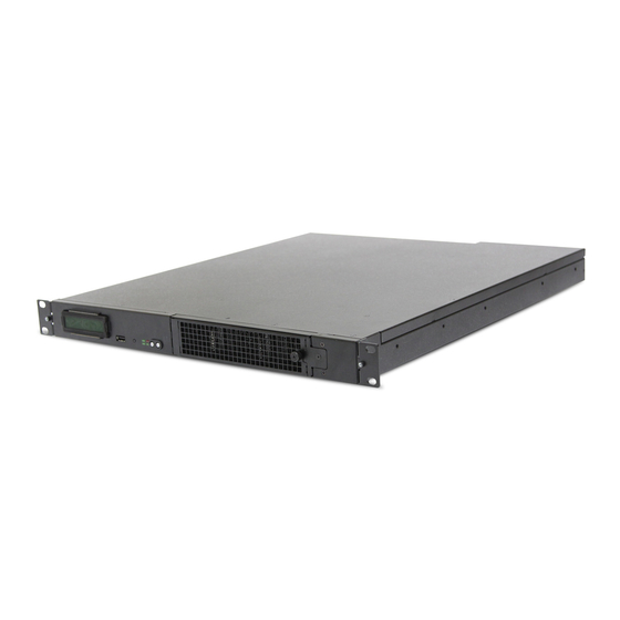
Chapter 1 Product Features Chapter 1� Product Features TB116-AN is a high density storage storage server that includes a mother board, a chassis, power supply, fan and backplane. For more information about our product, please visit our website at http://www.aicipc.com/en/index. -
Page 10: 1.2 Specifications
Dimensions BIOS Type • SPI (Serial Peripheral Interface) (W x D x H) inches : 17.2 x 21.3 x 1.7 5 FLASH Interface AIC Server Board Antlia Motherboard • ACPI1.0/2.0/3.0 One Intel® Xeon® Processor E3-1200 • PXE 2.0 • WOL... -
Page 11: 1�3 Features
Chapter 1 Product Features 1�3 Features TB116-AN is a reliable 1U storage server barebone with 10 hard drive disk bays that supports two Intel® Xeon® Scalable processors. This barebone consists of a Intel® Lewisburg C620 series Chipset, onboard baseboard management controller for system management and IPMI control and hot swap redundant fans. - Page 12 System HDD Activity LED Service ID LED On/Off System Reset Rear Panel TB116-AN provides 3 LAN ports (GbE RJ45 x 1, 10G SFP+ x 2), 2 USB 3.0 double stack Type A, 1 VGA port and 1 DB-9 COM-port. TB116-AN User's Manual...
- Page 13 Chapter 1 Product Features Major Components TB116-AN provides 650W 1+1 redundant power supply (Optional 750W/850W 1+1 redundant power supply) and 5 x 40 x 56 mm dual rotor fans. TB116-AN User's Manual...
-
Page 14: Chapter 2� Hardware Setup
2.1.1 Installing the CPU 1. Press the load lever to release the load plate. Load lever Load plate 2. Lift the load plate. 3. Remove the processor protective cover from CPU socket. TB116-AN User's Manual... - Page 15 Please keep the socket protective cover on when processor is not installed. 5. Close the load plate & load lever. Press to close TB116-AN User's Manual...
- Page 16 2. Tighten the four screws in a diagonal sequence, a couple of turns at a time, until all four screws are secure and the heatsink is securely fastened to the chassis. TB116-AN User's Manual...
- Page 17 Chapter 2 Hardware Setup 2.1.3 Heatsink Location TB116-AN User's Manual...
-
Page 18: 2�2 System Memory
Chapter 2 Hardware Setup 2�2 System Memory This server board supports up to four DDR4 1866/2133 Non-ECC UDIMM and ECC UDIMM Memo ry. JDIMM_B1 JDIMM_B0 JDIMM_A1 JDIMM_A0 CPU0 TB116-AN User's Manual... - Page 19 2.2.1 Populate DIMMs in the following order: DIMM Number DIMM arrangement JDIMM_B1 1 DIMMs JDIMM_B1 JCPU0 JDIMM_A1 JDIMM_B1 2 DIMMs JDIMM_A1 JDIMM_B1 JCPU0 JDIMM_A1 JDIMM_B0 JDIMM_B1 JDIMM_A1 JDIMM_B1 3 DIMMs JDIMM_B0 JCPU0 JDIMM_A0 JDIMM_A1 JDIMM_B0 JDIMM_B1 4 DIMMs JDIMM_A1 JDIMM_B1 JDIMM_A0 JDIMM_B0 JCPU0 TB116-AN User's Manual...
- Page 20 2.2.2 DIMM Installation Procedure Unlock a DIMM socket by pressing the retaining clips outward. Insert module vertically and press down until it snaps into place. Note: DIMM notch and socket bump must align as shown. DIMM notch TB116-AN User's Manual...
-
Page 21: 2�3 Removing And Installing The Top Cover
Step 2 Secure the screw x 12. 2.3.2 Removing the top cover Step 1 Press the release button on both sides of the enclosure. Step 2 Pull in a horizontal direction away from the front panel and lift upward. TB116-AN User's Manual... -
Page 22: 2�4 Removing And Installing Hard Disk Drive
Step 1 Remove the tray cover on top of the tray and loosen the thumb screw that is installed on the cover Step 2 Remove the tray onto the server board and loosen the thumb screw that is installed on the tray. TB116-AN User's Manual... - Page 23 2.4.4 Removing the 2.5" hard disk drive into the tray Step 1 Loosen the thumb screw on the bracket. Step 2 Remove the bracket. Step 3 Pull the hard disk drive out of the enclosure. Removal procedure TB116-AN User's Manual...
- Page 24 2.4.6 Removing the 3.5" hard disk drive Step 1 Remove the tray cover on top of the tray and loosen the thumb screw that is installed on the cover. Step 2 Remove the hard disk drive. TB116-AN User's Manual...
-
Page 25: 2�5 Removing And Installing The Fan Module
Step 2 Pull the handle on the fan module. 2.5.2 Removing the fan module Step 1 Loosen the screw and remove the bracket from the rear panel. Step 2 Pull the handle on the fan module. TB116-AN User's Manual... -
Page 26: 2�6 Removing And Installing The Power Supply Unit Module
Push the tray handle on the power supply module to install. 2.6.2 Removing the power supply unit module Step 1 Push the latch inward and hold the tray handle. Step 2 Pull the tray handle. TB116-AN User's Manual... -
Page 27: 2�7 Removing And Installing The Pcie Card
Step 2 Loosen the screw x 2 on bracket A and remove bracket A. Step 3 Loosen the screw on the PCIe card. Step 4 Slide the PCIe card away from the slot to remove. bracket A bracket B TB116-AN User's Manual... -
Page 28: 2�8 Removing And Installing The Tool-Less Blade Slide
Secure the inner chassis with the screws from the standard screw kit after the bayonets go through the holes and are accurately positioned. Bayonet on chassis shall be pre-formed as per the recommended dimension and location. TB116-AN User's Manual... - Page 29 Push the safety lock forward to secure the bracket. Be certain to check if the safety lock is in disenaged position before mounting the brackets. Release safety lock before mounting Push the safety lock forward to secure TB116-AN User's Manual...
- Page 30 Step 2 Refer to 2.9.3 to remove the outer cabinet from the slide rail. Step 3 Refer to 2.9.2 to remove the inner side rail from the enclosure. Step 4 Refer to 2.9.1 to push the inner slide rail into the blad slide. TB116-AN User's Manual...
-
Page 31: Chapter 3� Motherboard Settings
PCIE x4 PCIE x4 USB2.0 x2 AM2/AM4 USB2.0 x2 USB3.0 x2 (Rear Panel) (Front Panel) LAN x2 (By Header) USB3.0 x2 USB3.0 x2 USB2.0 x2 (Rear Panel) USB2.0 x2 SPIO USB2.0 x2 SPIO Interface SPI TPM (Front Panel) TB116-AN User's Manual... -
Page 32: 3�2 Motherboard Layout
Chapter 3 Motherboard Settings 3�2 Motherboard Layout RJ45 I350 RJ45 TB116-AN User's Manual... -
Page 33: 3�3 Motherboard Content List
Chapter 3 Motherboard Settings 3�3 Motherboard Content List TB116-AN User's Manual... -
Page 34: 3�4 Internal Connectors/Jumpers
Chapter 3 Motherboard Settings 3�4 Internal Connectors/Jumpers RJ45 I350 RJ45 COM_OUT_RXD5 COM_OUT_TXD5 TB116-AN User's Manual... - Page 35 Chapter 3 Motherboard Settings Internal Connectors/Jumpers TB116-AN User's Manual...
- Page 36 Chapter 3 Motherboard Settings Internal Connectors/Jumpers RJ45 I350 RJ45 TB116-AN User's Manual...
- Page 37 Chapter 3 Motherboard Settings Internal Connectors/Jumpers DDC_CLKO AVSYNCO VCC_VGA_5V AHSYNCO VGA_DACBO_F DDC_DATAO VGA_DACGO_F VGA_DACRO_F EXT_FM_BMC_GPIOD7 EXT_GPIOQ4_I2C14SCL EXT_GPIOC0_I2C10SCL EXT_GPIOQ5_I2C14SDA EXT_GPIOC1_I2C10SDA Setting (1-2) No REBOOT (Default) (2-3) REBOOT TB116-AN User's Manual...
- Page 38 PE_ PCH_TXC_DP10 NGFF_DEVSLP N.C. PE_ PCH_RXR_DP9 N.C. PE_ PCH_RXR_DN9 N.C. N.C. PE_ PCH_TXC_DN9 N.C. PE_ PCH_TXC_DP9 NGFF_PERST_N NGFF_CLKREQ_N CK_100M_NGFF_DN NGFF_PEWAKE_N CK_100M_NGFF_DP NGFF_MFG_DAT NGFF_MFG_CLK N.C. N.C. N.C. N.C. N.C. N.C. N.C. N.C. N.C. NGFF_SUSCLK_N NGFF_PEDET +3.3V +3.3V +3.3V TB116-AN User's Manual...
- Page 39 Chapter 3 Motherboard Settings Internal Connectors/Jumpers Setting SATA1 pin7 GND (1-2) (Default) SATA1 pin7 +5V (For SATA DOM with (2-3) pin7 + 5V) J33 J34 J37 J38 J44 J45 J46 J47 SATA_RXC_DP SATA_RXC_DN SATA_TXC_DN XDP_CPU2_MBP_N3 SATA_TXC_DP TB116-AN User's Manual...
- Page 40 Chapter 3 Motherboard Settings Internal Connectors/Jumpers RJ45 I350 RJ45 J49J J56J TB116-AN User's Manual...
- Page 41 Chapter 3 Motherboard Settings Internal Connectors/Jumpers TB116-AN User's Manual...
- Page 42 Chapter 3 Motherboard Settings Internal Connectors/Jumpers SMB_PMBUS_CLK CPU0_FAN_PWM SMB_PMBUS_DATA CPU0_FAN_TACH FM_PMBUS _ALERT_N +12V +3.3V TB116-AN User's Manual...
- Page 43 Chapter 3 Motherboard Settings Internal Connectors/Jumpers RJ45 I350 RJ45 TB116-AN User's Manual...
- Page 44 Chapter 3 Motherboard Settings Internal Connectors/Jumpers TB116-AN User's Manual...
- Page 45 Close: BMC SRST Enable BMC EXT REST (9-10) Open: Normal <Default> Close: BMC Ext REST Enable ME FIRMWARE UPDATE (11-12) Open: Normal <Default> Close: ME force update Password Clear Jumper (13-14) Open: Normal <Default> Close: Password clear TB116-AN User's Manual...
-
Page 46: 3�5 Leds
BMC RACK LAN activity detected (Only for RACK) LED2 BMC RACK LAN is not active (Only for RACK) BMC RACK LAN activity detected (Only for RACK) LED3 BMC RACK LAN is not active (Only for RACK) Blinking BMC working (Blinking) LED4 BMC No work TB116-AN User's Manual... - Page 47 LED2 LED1 PIN 1 Left LED(LED2) Left LED(LED1) Description (Activity) (Activity) No Link Link Green Green Linked at 10 Mbps Active Blinking Green Blinking Green Link Green Green Linked at 100 Mbps Active Blinking Green Blinking Green TB116-AN User's Manual...
- Page 48 Chapter 3 Motherboard Settings 3.5.3 RJ45 LED Definition LED2 LED1 LED4 LED3 RJ45 LED Definition (For AIC STD) Left LED (LED4, LED2,) Right LED (LED3, LED1,) Description ((Link/Activity)) (Speed) No Link Link Green Linked at 10 Mbps Active Blinking Green...
-
Page 49: Chapter 4. Bios Configuration Settings
Chapter 4 BIOS Configuration Settings Chapter 4. BIOS Configuration Settings 3.5.3 RJ45 LED Definition LED2 LED1 LED4 LED3 RJ45 LED Definition (For AIC STD) Left LED (LED4, LED2,) Right LED (LED3, LED1,) Description ((Link/Activity)) (Speed) No Link Link Green Linked at 10 Mbps... - Page 50 Chapter 4 BIOS Configuration Settings Identify the BIOS Version. Load Optimal Default setting. Save the setting and exit the BIOS setup utility. TB116-AN User's Manual...
-
Page 51: 4�1 Updating Bios
Chapter 4 BIOS Configuration Settings 4�1 Updating BIOS Important Notes: To identify the current BIOS version, please check out on BIOS setup. TB116-AN User's Manual... - Page 52 To use this utility, you must include the flash.bat , H2OFFT-D.exe, and bin file in the same folder. Please follow the instructions to update whole flash part: Execute flash.bat to update Flash in the DOS environment. Reboot system. TB116-AN User's Manual...
-
Page 53: Chapter 5. Bmc Configuration Settings
Insert Ethernet LAN cable into the BMC LAN port. There are two methods to setup BMC IP: BMC management port 5�1 Method 1 (Use the BIOS setup) 1. BIOS SETUP Server Mgmt BMC network configuration Configuration Address source Static TB116-AN User's Manual... - Page 54 Chapter 5 BMC Configuration Settings 2. Input IP address. Set static IP. TB116-AN User's Manual...
- Page 55 Chapter 5 BMC Configuration Settings 3. Input subnet mask address. TB116-AN User's Manual...
-
Page 56: 5�2 Method 2 (Use A Dos Tool - Syscheck)
5�2 Method 2 (Use a Dos Tool - Syscheck) 1 . Type : sc –lanset. 2. Modify IP setting. Note: type 1 for selecting static IP mode or type 2 for selecting DHCP mode. 3. Input the IP address. TB116-AN User's Manual... - Page 57 Below IP address is an example using a default IP setting. User is allowed to change the IP address for realistic use. 5. Finish the BMC IP configuration. Note: Type sc.exe –langet command to obtain BMC IP and MAC address. TB116-AN User's Manual...
-
Page 58: 5�3 Connect To Bmc
Password: admin Note: The default user name and password are in lower-case characters. Note: Users who login with the admin user name and password will have full administrative power. The admin password can be changed after login. TB116-AN User's Manual... - Page 59 Chapter 5 BMC Configuration Settings 3.Dashboard 4. Server Health - Sensor Readings: TB116-AN User's Manual...
- Page 60 Chapter 5 BMC Configuration Settings 5. Configuration Refer to AIC BMC User Guide for more information on AIC BMC. Mouse Mode setting: For Windows OS environment, set mode to absolute. For Linux OS environment, set mode to relative TB116-AN User's Manual...
- Page 61 Chapter 5 BMC Configuration Settings 6. Remote Control: Environmental setting: Press “ALT+C” for local and remote OS mouse control switching. TB116-AN User's Manual...
-
Page 62: 5�4 Updating Bmc Firmware
A:>cd SB301C01 A:\ SB301C01>a.bat This is just an example. The latest BMC firmware version is available from the FAE or AIC website. 4. After updating the BMC firmware, please turn off and then turn on the system. Notes: 1. DO NOT USE EMM386 IN DOS ENVIRONMENT WHEN UPDATING FIRMWARE OR YOU WILL GET A FAIL. -
Page 63: Chapter 6� Technical Support
Chapter 1 Product Introduction Chapter 1 Product Introduction Chapter 6� Technical Support www�aicipc�com • TAIWAN Tel: +886 3 433 9188 Fax: +886 3 287 1818 Email: sales@aicipc�com�tw • CHINA Tel: +86�21�54961421, +86�21�54961422 Fax: Extension: 608 Email Technical Support: support@aicipc�com • AMERICA - West coast Tel: +1�909�895�8989 Fax: +1�909�895�8999 Email: sales@aicipc�com...
Need help?
Do you have a question about the TB116-AN and is the answer not in the manual?
Questions and answers