Table of Contents
Advertisement
Quick Links
Advertisement
Table of Contents

Subscribe to Our Youtube Channel
Related Manuals for AIC Rack Venus


Summary of Contents for AIC Rack Venus
- Page 1 Rack Venus Server Rack User's Manual UM_Rack Venus_v1_110619...
-
Page 2: Table Of Contents
3.5.1 How to enable/disable T10 zoning ..............26 3.5.2 How to configure T10 zoning ................27 3.5.3 How to get all revisions in AIC SAS 12G Expander ........29 3.5.4 How to configure temperature sensor ............30 3.5.5 How to configure enclosure address .............. 31 3.5.6 How to configure standby timer for all disk drives ........ - Page 3 3.5.7 How to configure wide port checker ............... 33 3.5.8 How to configure serial number ..............35 3.5.9 How to power off/on all disk drives automatically ........36 3.5.10 How to configure EDFB ................. 37 3.5.11 How to configure power setting ..............38 3�6 SES Inband Features �����������������������������������������������������������������������40 3.6.1 SES pages support ..................
- Page 4 5.4.12 Sign Out ......................83 Chapter 6. Hardware Specification ��������������������������������������������������� 84 6�1 Rack Backplane ������������������������������������������������������������������������������84 6.1.1 Placement ......................84 6.1.2 Connector and Jumper ..................85 6.1.3 System LED Indicator ..................86 6�2 RMC ����������������������������������������������������������������������������������������������88 6.2.1 RMC Placement ....................88 6.2.2 Connector and Jumper ..................88 6.2.3 System LED Indicator ..................
- Page 5 Copyright © 2019 AIC, Inc� All Rights Reserved� This document contains proprietary information about AIC products and is not to be disclosed or used except in accordance with applicable agreements.
- Page 6 Document Release History Release Date Version Update Content November Release to public. 2019...
-
Page 7: Preface
Disclaimer AIC shall not be liable for technical or editorial errors or omissions contained herein. The information provided is provided "as is" without warranty of any kind. To the extent permitted by law, neither AIC or its affiliates, subcontractors or suppliers will be liable for incidental, special or consequential damages including downtime cost;... -
Page 8: Safety Instructions
Safety Instructions Before getting started, please read the following important cautions: • All cautions and warnings on the equipment or in the manuals should be noted. • Most electronic components are sensitive to electrical static discharge. Therefore, be sure to ground yourself at all times when installing the internal components. •... - Page 9 • If the equipment is not used for a long time, disconnect the equipment from mains to avoid being damaged by transient over-voltage. • Never open the equipment. For safety reasons, only qualified service personnel should open the equipment. • If one of the following situations arise, the equipment should be checked by service personnel: 1.
-
Page 10: Rack System Precautions
Rack System Precautions Elevated Operating Ambient Temperature The rack design should take into consideration the maximum operating ambient temperature for the unit. If installed in a closed or multi-unit rack assembly, the operating ambient temperature of the rack environment may be greater than room ambient. Therefore, consideration should be given to installing the system in an environment compatible with the system’s maximum rated ambient temperature. -
Page 11: About This Manual
Chapter 9 Product-End-of_Life Instruction This offers a recommended instruction about the product-end-of-life. Chapter 10 Technical Support For more information or suggestion, please contact the nearest AIC corporation representative in your district or visit the AIC website: https://www.aicipc.com/ en/productdetail/51090. It is our greatest honor to provide the best service for our... -
Page 12: Chapter 1� Product Features
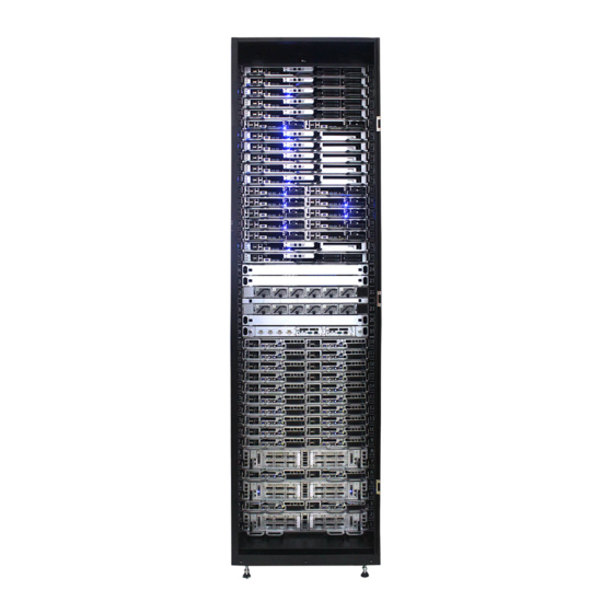
SB101-LB User Manual 1�1 Feature Rack Venus is a 42OU server rack that offers maximized performance, enhanced security, and easy maintanance for datacenters and cloud computing applications. With the design of 15KW with 3000W power supply unit and configurable smart cooling system... -
Page 13: 1�2 Tools Required
Rack Venus User Manual Chapter 1. Product Features 1�2 Tools Required The rack shipping kit contains the following tools and equipment that is required for installing and servicing the rack: Cage nut toolL eveling wrench 3-mm hex wrench 5-mm hex wrench... -
Page 14: Moving The Rack Cabinet
SB101-LB User Manual Chapter 1. Product Features 1�3�2 Moving the Rack Cabinet CAUTION Very important: It requires at least 5 people to move the rack cabinet for safety puroose. -
Page 15: Smart Rack Specifications
Rack Venus User Manual Chapter 1. Product Features 1.4 Smart Rack Specifications AIC Venus Rack Model Name 42 OU height Rack Dimension 600 x 1185 x 2230.5 mm (WxDxH) 23.7 x 46.7 x 87.8 inches • 2 OU reserved for power bank •... -
Page 16: Node Specifications
536 x 800 x 48 Dimension (WxDxH) Inches: 21" x 31.5" x 1.89" Spec per Node Mother Board AIC Server Board PAVO Intel® Xeon® Processors Scalable Family CPU Type UPI Speeds : 9.6 GT/s, 10.4 GT/s CPU Socket Socket P0 (LGA-3647 Socket) -
Page 17: Ou Nvme Node
Rack Venus User Manual Chapter 1. Product Features 1�5�2 1 OU NVMe Node 536 x 800 x 48 Dimension (WxDxH) Inches: 21" x 31.5" x 1.89" Spec per Node Mother Board AIC Server Board PAVO Intel® Xeon® Processors Scalable Family CPU Type UPI Speeds : 9.6 GT/s, 10.4 GT/s... -
Page 18: 1Ou Dual Node
536 x 800 x 48 Dimension (WxDxH) Inches: 21" x 31.5" x 1.89" Spec per Node Mother Board AIC Server Board PAVO Intel® Xeon® Processors Scalable Family CPU Type UPI Speeds : 9.6 GT/s, 10.4 GT/s CPU Socket Socket P0 (LGA-3647 Socket) -
Page 19: 2Ou 30 Jbod
Rack Venus User Manual Chapter 1. Product Features 1�5�4 2OU 30 JBOD Form Factor 2 OU Rackmount External I/O Ports 8 x 12Gb/s mini-SAS ports Storage (15+15) 3.5" or 2.5" SAS/SATA hot-pluggable HDDs Management port BMC (IPMI) management Expansion Support... -
Page 20: Chapter 2� Hardware Setup
Chapter 2� Hardware Setup Rack Venus User Manual Chapter 2. Hardware Setup This section describes a simple instruction guide for installing the hardware components on the serverboard system. Turn off and unplug all system and peripheral devices before proceeding. To ensure a safe and easy setup, you need to prepare before installation or removal: ... -
Page 21: 2�1 Power Distribution Unit Module
Rack Venus User Manual Chapter 2. Hardware Setup 2�1 Power Distribution Unit Module 2�1�1 Removing the PDU Module Step 1 Push the latch on the module. Step 2 Hold the handlebar and pull the handlebar out gently to slide the module out of the socket. -
Page 22: 2�2 Fan Module
Rack Venus User Manual Chapter 2. Hardware Setup 2�2 Fan Module 2�2�1 Removing the Fan Module Step 1 Remove the handle from the fan module. Step 2 Pull the handle to remove the fan module from the enclosure. 2�2�2 Installing the Fan Module Step 1 Align the fan module with the opening in the rack cabinet. -
Page 23: 2�3 Sata Node Server
Rack Venus User Manual Chapter 2. Hardware Setup 2�3 SATA Node Server 2�3�1 Replacing the SATA Node Server Step 1 Push the latches on the node and pull the handlebars on the node to remove. Step 2 Replace the dual node with a new one and install it into the rack... -
Page 24: Replacing The Components In The Sata Node
Rack Venus User Manual Chapter 2. Hardware Setup 2�3�2 Replacing the Components in the SATA Node Step 1 Push the latch on the node upward Step 2 Pull the handle bar on the node to remove the node without removing the node cage. -
Page 25: 2�4 Nvme Node Server
Rack Venus User Manual Chapter 2. Hardware Setup 2�4 NVMe Node Server 2�4�1 Replacing the NVMe Node Step 1 Push the latches on the node and pull the handlebars on the node to remove. Step 2 Replace the dual node with a new one and install it into the rack... -
Page 26: 2�5 Dual Node Server
Rack Venus User Manual Chapter 2. Hardware Setup 2�5 Dual Node Server 2�5�1 Replacing the Dual Node Server Step 1 Make sure the system is turned off. Step 2 Remove all the cables from front panel and make room for the dual node to be removed. -
Page 27: Replacing The Components In The Dual Node
Rack Venus User Manual Chapter 2. Hardware Setup 2�5�2 Replacing the Components in the Dual Node Step 1 Push the latch on the node upward Step 2 Pull the handle bar on the node to remove the node without removing the node cage. -
Page 28: 2�6 Rack Management Control Module
Rack Venus User Manual Chapter 2. Hardware Setup 2�6 Rack Management Control Module 2�6�1 Removing the RMC Module Step 1 Remove the thrumb screws holding the bracket kit into place. Step 2 Pull the RMC module from the rack cabinet. -
Page 29: 2�7 Rack Backplane Module
Rack Venus User Manual Chapter 2. Hardware Setup 2�7 Rack Backplane Module 2�7�1 Replacing the rack backplane Module Step 1 Remove the LED panel by dislodging the screws x 4. Step 2 Remove the bracket frame with the fan module by disloging the screws x 4. -
Page 30: Chapter 3. 2U30 Jbod Subsystem Configuration
Chapter 3. 2U30 JBOD Subsystem Configuration Rack Venus User Manual Chapter 3. 2U30 JBOD Subsystem Configuration Settings 3.1 Supported Configuration and Unsupported Feature 3.1.1 Supported Configuration ..Host-1 Host-n AIC 12G Expander Controller NOTE To have mutiple host access support (the host number can be up to the number of wide... -
Page 31: 3�3 Utility Setup On Host
Rack Venus User Manual Chapter 3. 2U30 JBOD Subsystem Configuration Settings 3�3 Utility Setup on Host Step 1 Set up the host and RS232 connection Set up RS232 connection application into your host as shown in the example process below. - Page 32 Rack Venus User Manual Chapter 3. 2U30 JBOD Subsystem Configuration Settings Step 3 Enter a new name for the icon in the field below and click OK. Step 4 Connect by selecting an option in the drop down menu circled in red below...
- Page 33 Rack Venus User Manual Chapter 3. 2U30 JBOD Subsystem Configuration Settings Step 5 Under “Bits per second,” select 38400. Under “Flow control,” select 'None.' Click OK when you have finished your selections. Step 6 After step 5, you will enter hyper terminal screen. Press "Enter" key and the...
-
Page 34: 3�4 Updating Firmware And Mfg Through Console Port
Rack Venus User Manual Chapter 3. 2U30 JBOD Subsystem Configuration Settings 3�4 Updating Firmware and MFG through Console Port Step 1 Please type in “fdl 0 0” in command line to update the firmware. Step 2 Select the tool bar ''Transfer'' ''Send File'' within 10 seconds. - Page 35 Rack Venus User Manual Chapter 3. 2U30 JBOD Subsystem Configuration Settings Step 3 Select the Firmware file. Set the Protocol type as “Xmodem” and then press the “Send” button. Step 4 After completing the firmware update, the screen will show “Buffer Download...
- Page 36 Rack Venus User Manual Chapter 3. 2U30 JBOD Subsystem Configuration Settings Step 5 Type in “fdl 83 0 ” in the commond line to update the MFG. Step 6 Go to the "Transfer" menu, and then select “Send file” within 10 seconds.
-
Page 37: Configure The Command Line Interface Operation
Rack Venus User Manual Chapter 3. 2U30 JBOD Subsystem Configuration Settings 3.5 Configure the Command Line Interface Operation 3�5�1 How to enable/disable T10 zoning The default T10 zoning configuration is off. (A) Check the current zoning state cmd> phyzone state... -
Page 38: How To Configure T10 Zoning
Rack Venus User Manual Chapter 3. 2U30 JBOD Subsystem Configuration Settings 3.5.2 How to configure T10 zoning After enabling T10 zoning, five predefined groups are Group1, Group8, Group9, Group10,and Group11. Each PHY should be in one of the five groups, and all PHYs in a wide port should be in the same group. - Page 39 Rack Venus User Manual Chapter 3. 2U30 JBOD Subsystem Configuration Settings...
-
Page 40: How To Get All Revisions In Aic Sas 12G Expander
Rack Venus User Manual Chapter 3. 2U30 JBOD Subsystem Configuration Settings 3�5�3 How to get all revisions in AIC SAS 12G Expander (A) Expander firmware revision cmd> rev (B) Expander configuration revision cmd> showmfg (C) MCU firmware revision and sensor information... -
Page 41: How To Configure Temperature Sensor
Rack Venus User Manual Chapter 3. 2U30 JBOD Subsystem Configuration Settings 3.5.4 How to configure temperature sensor Four temperature settings in Celsius are T1, T2, warning threshold, and alarm (critical) threshold. The T1, T2 and alarm (critical) threshold are applied to the smart fan function. -
Page 42: How To Configure Enclosure Address
Rack Venus User Manual Chapter 3. 2U30 JBOD Subsystem Configuration Settings 3.5.5 How to configure enclosure address (A) Get the current enclosure address cmd> enclosure_addr Enclosure Address: 0x500605B0000272BF (B) Set the enclosure address with 0x500605B0000272BF. The new setting will take effect after reset. -
Page 43: How To Configure Standby Timer For All Disk Drives
Rack Venus User Manual Chapter 3. 2U30 JBOD Subsystem Configuration Settings 3.5.6 How to configure standby timer for all disk drives This feature is applicable for SAS/SATA drives. Standby timer is in units of minutes. Setting standby timer with 0 minute disables this feature. -
Page 44: How To Configure Wide Port Checker
This feature is applicable for SAS drives instead of SATA drives. If there is no connection with any active SAS initiator by checking all wide ports, AIC Expander Controller stops all attached SAS drives to save power consumption of SAS drives. - Page 45 Rack Venus User Manual Chapter 3. 2U30 JBOD Subsystem Configuration Settings...
-
Page 46: How To Configure Serial Number
Rack Venus User Manual Chapter 3. 2U30 JBOD Subsystem Configuration Settings 3.5.8 How to configure serial number (A) Get the current serial number cmd> serial_number Expander number: 421-12021704510010 or Expander number: 421- 12021704510010 Enclosure number: 526-12071100500088 (B) Only set Expander serial number with 421-12021704510010. -
Page 47: How To Power Off/On All Disk Drives Automatically
3�5�9 How to power off/on all disk drives automatically This feature is applicable for SAS/SATA drives. If there is no connection with any active SAS initiator by checking all wide ports, AIC Expander Controller powers off all attached SAS/SATA drives to save power consumption. Otherwise, AIC Expander Controller powers on all attached SAS/SATA drives to provide drive access service to any active SAS initiator. -
Page 48: How To Configure Edfb
Rack Venus User Manual Chapter 3. 2U30 JBOD Subsystem Configuration Settings 3.5.10 How to configure EDFB The default EDFB configuration is off. (A) Check the current configuration cmd> edfb EDFB is OFF (B) Enable the edfb cmd>edfb on (C) Disable the edfb... -
Page 49: How To Configure Power Setting
Rack Venus User Manual Chapter 3. 2U30 JBOD Subsystem Configuration Settings 3.5.11 How to configure power setting This feature is for restoring on AC power loss. Three supported options are "keep off," "keep on," and "keep last state." The default setting is "keep off."... - Page 50 Rack Venus User Manual Chapter 3. 2U30 JBOD Subsystem Configuration Settings...
-
Page 51: 3�6 Ses Inband Features
Rack Venus User Manual Chapter 3. 2U30 JBOD Subsystem Configuration Settings 3�6 SES Inband Features 3�6�1 SES pages support 00h - List of supported diagnostic pages 01h - SES configuration 02h - SES enclosure control / enclosure status 07h - SES element descriptor... -
Page 52: Implementation On Ses Elements
Rack Venus User Manual Chapter 3. 2U30 JBOD Subsystem Configuration Settings 3�6�3 Implementation on SES Elements Only the fields highlighted in green are supported. 3.6.3.1 Temperature Sensor Element (A) Temperature Sensor Control Element Byte / Bit COMMON CONTROL SELECT PRDFAIL... - Page 53 Rack Venus User Manual Chapter 3. 2U30 JBOD Subsystem Configuration Settings 3.6.3.2 Enclosure Element (A) Enclosure Control Element Byte / Bit COMMON CONTROL SELECT PRDFAIL DISABLE RST SWAP ELEMENT STATUS CODE RQST Reserved IDENT POWER CYCLE POWER CYCLE DELAY REQUEST...
- Page 54 Rack Venus User Manual Chapter 3. 2U30 JBOD Subsystem Configuration Settings 3.6.3.3 Array Device Element (A) Array Device Control Element Byte / Bit COMMON CONTROL SELECT PRDFAIL DISABLE RST SWAP Reserved RQST RQST RQST RQST IN RQST RQST HOT RQST R/R...
- Page 55 Rack Venus User Manual Chapter 3. 2U30 JBOD Subsystem Configuration Settings (B) Array Device Status Element Byte / Bit COMMON CONTROL Reserved PRDFAIL DISABLE RST SWAP ELEMENT STATUS CODE RSVD CONS IN CRIT IN FAILED REBULD/ DEVICE SPARE CHECK ARRAY...
-
Page 56: Ses Element Control Functions
Rack Venus User Manual Chapter 3. 2U30 JBOD Subsystem Configuration Settings 3�6�4 SES Element Control Functions 3.6.4.1 LED indicators (blue and red) associated with an attached disk drive Array Device Slot control element Byte / Bit COMMON CONTROL SELECT PRDFAIL... - Page 57 We use the software package "sg3_utils" on Linux for example, and have a SAS HBA and a cable to connect your host with the expander. (A) Show the device for AIC Expander Controller (canister) $ sg_map -i /dev/sg2 AIC 12G Rack 2U30 Exp 0c04 (B) Get the current state of a slot power.
- Page 58 "sg3_utils" on Linux for example, and have a SAS HBA and a cable to connect your host with the expander. (A) Show the device for AIC Expander Controller (canister) $ sg_map -i /dev/sg2 AIC 12G Rack 2U30 Exp...
- Page 59 We use the software package "sg3_utils" on Linux for example, and have a SAS HBA and a cable to connect your host with the expander. (A) Show the device for AIC Expander Controller (canister) $ sg_map -i /dev/sg2 AIC 12G Rack 2U30 Exp...
-
Page 60: Chapter 4� 2U30 Jbod Bmc Settigs
Chapter 4� 2U30 JBOD BMC Settigs Rack Venus User Manual Chapter 4. JBOD 2U30 BMC Settings 4�1 Utility Setup on Host Please refer to Section 3.2. 4�2 Connect Host to BMC by RS232 1. Type in "[" and the IPMI serial interface will appear. - Page 61 Rack Venus User Manual Chapter 4. JBOD 2U30 BMC Settings 2. Find LAN information. Find LAN static IP /DHCP [30 00 02 01 04 00 00 ] Find LAN IP [30 00 02 01 03 00 00 ] Find submask...
- Page 62 Rack Venus User Manual Chapter 4. JBOD 2U30 BMC Settings 4. Get LAN2(eth1) information Get LAN static IP /DHCP [30 00 02 08 04 00 00 ] Get LAN IP [30 00 02 08 03 00 00 ] Get submask...
-
Page 63: Sensor And Fan Location
Rack Venus User Manual Chapter 4. JBOD 2U30 BMC Settings 4.3 Sensor and Fan Location Sensor Location JBOD Reer Side HDD BP HDD BP JBOD Front Side... -
Page 64: Login
Rack Venus User Manual Chapter 4. JBOD 2U30 BMC Settings 4.4 Login Open a web browser, enter default IP and press "Enter." When the login window appears, set the user name and password to Admin. Click Log In to continue. -
Page 65: 4�5 Web Gui
Rack Venus User Manual Chapter 4. JBOD 2U30 BMC Settings 4�5 Web GUI 4�5�1 Menu Bar Click to select the options of the menu bar. Menu Description The Dashboard page gives the overall information about the Dashboard status of a device. -
Page 66: Dashboard
Rack Venus User Manual Chapter 4. JBOD 2U30 BMC Settings 4�5�2 Dashboard The Dashboard page displays device, system information, and assert logs. Click Dashboard on the menu bar to view the overall information of the server. Power Cycle: This page navigates you to view the Power Control page. -
Page 67: Fru Information
Rack Venus User Manual Chapter 4. JBOD 2U30 BMC Settings 4�5�4 FRU information This page displays the BMC FRU file information. On selecting a particular FRU Device ID its corresponding FRU information will be displayed. • Available FRU Devices •... -
Page 68: Logs & Reports
Rack Venus User Manual Chapter 4. JBOD 2U30 BMC Settings 4.5.6 Logs & Reports IPMI Event Log This page displays the list of events incurred by different sensors on this device. Click on a record to see the details of that entry. You can use the sensor type or sensor name filter options to view those specific events logged in the device. - Page 69 Rack Venus User Manual Chapter 4. JBOD 2U30 BMC Settings • Media Redirection Settings: This page is used to configure the media into BMC for redirection. General Settings: This option is used to configure General Media Settings. VMedia Instance Settings: This page is used to configure Virtual Media device settings.
-
Page 70: Power Control
Rack Venus User Manual Chapter 4. JBOD 2U30 BMC Settings 4�5�8 Power Control The Power Control page allows you to view and control the power of your server. 4�5�9 Hard Disk Monitor The Hard Disk Monitor page allows to remotely manage hard disk monitors. -
Page 71: Maintenance
Rack Venus User Manual Chapter 4. JBOD 2U30 BMC Settings 4�5�10 Maintenance The Maintenance page allows you to do maintenance tasks on the device. Firmware Image Location: Protocol to be used to transfer the firmware image into the BMC. Firmware Information: Describes the information of the active BMC, Expander and MFG image Firmware Update: This wizard takes you through the process of firmware upgradation. -
Page 72: 4�6 Firmware Safety Mode
Rack Venus User Manual Chapter 4. JBOD 2U30 BMC Settings 4�6 Firmware Safety Mode If you update process fail or primary firmware suffers some error, it will boot in safety mode. Safety mode: This mode is useing update BMC firmware for recover primary frmware, when boot in this firmware, the only one thing you can do is update BMC firmware again. -
Page 73: Menu Bar
Rack Venus User Manual Chapter 4. JBOD 2U30 BMC Settings 4�6�2 Menu Bar Click to select the options of the menu bar. Menu Description The Dashboard page gives the overall information about the Dashboard status of a device. The FRU Information page displays the details for FRU FRU Information devices in the system. -
Page 74: Fru Information
Rack Venus User Manual Chapter 4. JBOD 2U30 BMC Settings 4�6�4 FRU information This page displays the BMC FRU file information. On selecting a particular FRU Device ID its corresponding FRU information will be displayed. • Available FRU Devices •... -
Page 75: Maintenance
Rack Venus User Manual Chapter 4. JBOD 2U30 BMC Settings 4�6�6 Maintenance The Maintenance page allows you to do maintenance tasks on the device. Firmware Image Location: Protocol to be used to transfer the firmware image into the BMC. Firmware Information: Describes the information of the active BMC image. -
Page 76: 4�7 Firmware Update Step
Rack Venus User Manual Chapter 4. JBOD 2U30 BMC Settings 4�7 Firmware Update Step Step 1 Click Maintenance to enter to Firmware Update page. Step 2 Choose the Firmware image and click Start firmware update button to upgrade the current device firmware. - Page 77 Rack Venus User Manual Chapter 4. JBOD 2U30 BMC Settings Step 3 Wait for the firmware to update and re-login web UI again after the update is complete. The pop up box“firmware reset is called close the current session and open a new session...
-
Page 78: Chapter 5. Rmc Configuration Settings
Chapter 5. RMC Configuration Settings Rack Venus User Manual Chapter 5. RMC Configuration Settings 5�1 Utility Setup on Host As shown drawing as below Connect management switch to DHCP server. Connect RMC serial port (DB9 connector in RMC) to your computer. (For example,... -
Page 79: Sensor And Fan Location
Rack Venus User Manual Chapter 5. RMC Configuration Settings 5.2 Sensor and Fan Location Sensor Location Conn. Conn. Board Board TOP VIEW L_U2 R_U2 L_Exp._Rear R_Exp._Rear Expander_Temp L_Exp._Front R_Exp._Front L_U1R... - Page 80 Rack Venus User Manual Chapter 5. RMC Configuration Settings Fan Location Fan 6-8 Fan 6-7 Fan 6-6 Fan 6-5 Fan 6-4 Fan 6-3 Fan 6-2 Fan 6-1 Fan 5-8 Fan 5-7 Fan 5-6 Fan 5-5 Fan 5-4 Fan 5-3 Fan 5-2...
-
Page 81: 5�3 Web Gui
Rack Venus User Manual Chapter 5. RMC Configuration Settings 5�3 Web GUI 5.3.1 Login Open a web browser and enter the default IP. Proceed to press enter. When the login window appears, set the user name to Admin and leave the password box empty. -
Page 82: Menu Bar
Rack Venus User Manual Chapter 5. RMC Configuration Settings 5�4�2 Menu Bar Click to select the options of the menu bar. Menu Description The Dashboard page gives the overall information about the status of Dashboard a device. Sensor The Sensor Readings page displays all the sensor related information. -
Page 83: User Information And Quick Button
Rack Venus User Manual Chapter 5. RMC Configuration Settings 5�4�3 User Information and Quick Button The user information and quick access buttons are located at the top right corner. It displays the logged-in user, his/her privilege and the four quick buttons allowing you to perform different functions. -
Page 84: Dashboard
Rack Venus User Manual Chapter 5. RMC Configuration Settings 5�4�4 Dashboard The Dashboard page gives the overall information about the status of a device. To open the Dashboard page, click Dashboard from the menu bar. A sample screenshot of the Dashboard page is shown below. -
Page 85: Fru Information
Rack Venus User Manual Chapter 5. RMC Configuration Settings 5�4�6 FRU Information FRU Information page displays the BMC’s FRU device information. FRU page shows information like Basic Information, Chassis Information, Board Information and Product Information of the FRU device. To open the FRU Information page, click FRU Information from the menu bar. Select a FRU Device ID from the FRU Information section to view the details of the selected device. -
Page 86: Node List (Rmc Only)
Rack Venus User Manual Chapter 5. RMC Configuration Settings 5�4�7 Node List (RMC only) Node List Information page displays the BMC’s Node device information. Node List page shows Node information. To open the Node List Information page, click Node List from the menu bar. Select a Node Device item from the Node List Information section to view the details of the selected device. - Page 87 Rack Venus User Manual Chapter 5. RMC Configuration Settings Node detail Select a particular Node item from the Node lists. The Node Detail Information will be displayed as shown below. Node Information • Node Location • Health • Power •...
- Page 88 Rack Venus User Manual Chapter 5. RMC Configuration Settings IP Setting The various options of IP Setting are given below. Field Description IP Address Source Choose the source of DHCP or Static IP Address These fields are for specifying the static IPv4 address to be configured to the device.
-
Page 89: Logs & Reports
Rack Venus User Manual Chapter 5. RMC Configuration Settings 5.4.8 Logs & Reports The Logs & Reports page displays the following information: IPMI Event Log, System Log, Audit Log, User Log IPMI Event Log This page displays the list of event logs occurred by the different sensors on this device. - Page 90 Rack Venus User Manual Chapter 5. RMC Configuration Settings Audit Log Audit Log page will display all the system events occurred in this device that has been already configured. NOTE Logs have to be configured under Settings > Log Settings > Advanced Log Settings in order to display any entries.
-
Page 91: Settings
Rack Venus User Manual Chapter 5. RMC Configuration Settings 5�4�9 Settings This group of pages allows you to access various configuration settings. A screenshot of Configuration Group menu is shown below. Field Description Date & Time This field is used to set the date and time on the BMC. -
Page 92: Rack Control
Rack Venus User Manual Chapter 5. RMC Configuration Settings 5�4�10 Rack Control This page allows you to view and rack control of your server. To open Rack Control, click Rack Control from the menu bar. A sample screenshot of Power Control is shown below. -
Page 93: Maintenance
Rack Venus User Manual Chapter 5. RMC Configuration Settings 5�4�11 Maintenance This group of pages allows you to do maintenance tasks on the device. A sample screenshot of Power Control is shown below. The various options of Power Control are given below. -
Page 94: Sign Out
Rack Venus User Manual Chapter 5. RMC Configuration Settings 5�4�12 Sign Out o log out from the web GUI, click the admin on the top right corner of the screen. A sample screenshot of admin option is shown below. Click Sign Out to perform log out from the web GUI. A Warning message will be... -
Page 95: Chapter 6. Hardware Specification
Chapter 6. Hardware Specification Rack Venus User Manual Chapter 6. Hardware Specification This chapter provides detailed information on hardware specifications. 6�1 Rack Backplane 6�1�1 Placement Top View PDB0 PDB1 PDB2 PDB3 PDB4 PDB5 FAN1 FAN3 JID1 FAN2 FAN4 IPMB1 JNGFF1... -
Page 96: Connector And Jumper
Rack Venus User Manual Chapter 6. Hardware Specification 6�1�2 Connector and Jumper Connector/Jumper Location Connector/Jumper Location Rack BP Connect to PDB0~PDB5 Power Connector PDB Board IPMB CONNECTOR IPMB1 LED Control J2002 LAN1 ROM Module JNGFF1 Debug Port Backup ROM Module... -
Page 97: System Led Indicator
Rack Venus User Manual Chapter 6. Hardware Specification 6.1.3 System LED Indicator LED7 LED8 LED10 LED11 LED12 Top View 10Hz : ARM Running on Flash. (instruction fetch from flash). 2Hz : ARM Running on DRAM without interrupt enabled. (instruction fetch from DRAM) On (Blinking) 0.5Hz : ARM Running on DRAM with interrupt... - Page 98 Rack Venus User Manual Chapter 6. Hardware Specification LED1 LED3 LED5 LED9 Bottom View LED2 LED4 LED6 Green Rack backplane fan status successful. LED1~LED6 FAN Status Rack fan status failure. backplane Green Rack backplane status successful. LED9 RACK BP Status...
-
Page 99: 6�2 Rmc
Rack Venus User Manual Chapter 6. Hardware Specification 6�2 RMC 6�2�1 RMC Placement Top View Bottom View AST2520 Main DRAM FLASH JUART1 64Mb JCOM1 JCOM2 Backup FLASH 64Mb RJ45 6�2�2 Connector and Jumper Connector/Jumper Location Connector/Jumper Location LAN PORT SWRST1... -
Page 100: System Led Indicator
Rack Venus User Manual Chapter 6. Hardware Specification 6.2.3 System LED Indicator HBLED1 STATLED1 UIDLED PWRLED in button in button System ID detected. BMC ID LED Blue (SWUID1) System ID not detected. System has failed. BMC Status LED (STATLED1) System actvity is normal. -
Page 101: 6�3 Rmc Backplane
Rack Venus User Manual Chapter 6. Hardware Specification 6�3 RMC Backplane 6�3�1 Placement PORT5 PORT4 PORT3 PORT2 PORT1 PORT0 PTULAN1 PTULAN0 UPLAN1 UPLAN0 Bottom... -
Page 102: Connector
Rack Venus User Manual Chapter 6. Hardware Specification 6�3�2 Connector Connector/Jumper Location Connector/Jumper Location PSU Control Signal BK0, BK1 LAN For PSU PTULAN0, PTULAN1 Power Connector J4, J5 LAN For External UPLAN0, UPLAN1 LAN For Node PORT0~PORT5 RMC Mode PCIE1, PCIE2... -
Page 103: 6�4 Power Distribution Unit
Rack Venus User Manual Chapter 6. Hardware Specification 6�4 Power Distribution Unit 6�4�1 Placement Top View Rear View... -
Page 104: Connector Location
Rack Venus User Manual Chapter 6. Hardware Specification 6.4.2 Connector Location 12VSB 12VSB 12V_2 12V_2 12V_1 12V_1 PWOK_L RESET 5VSB 5VSB SMB_ALERT_L IN0K_L 5VSB SGND PSON_SHELF_L I2C_SDA I2C_SCL 5VSB 5VSB 5VSB... -
Page 105: 7�1 Block Diagram
Chapter 7� Pavo Serverboard Rack Venus User Manual Chapter 7. Pavo Serverboard This section describes the jumpers, internal connectors, and internal LED settings on the Pavo motherboard. The motherboard layout and jumper settings are listed below. 7�1 Block Diagram... -
Page 106: Content List
Rack Venus User Manual Chapter 7. Pavo Serverboard 7.2 Content List Connector and Header Location Connector and Header Location COM Port by 3.5mm Phone Jack 22 PMBUS Header 2b 2 x USB 3.0 Type A Connector 23b PCIe Slot (x24) -
Page 107: 7�3 Placement
Rack Venus User Manual Chapter 7. Pavo Serverboard 7�3 Placement CPU0 CPU0 CPU1 CPU1... -
Page 108: 7�4 Connector And Jumper
Rack Venus User Manual Chapter 7. Pavo Serverboard 7�4 Connector and Jumper 6a ~ 6b COM Header (J11, J12) 7 Front VGA Header (J7) 8 UID LED Header (J15) 9 10 UID_LED P5V_AUX 11 UART Header (J17) UART_RX UART_TX 10 Front I/O USB 3.0 Header... - Page 109 Rack Venus User Manual Chapter 7. Pavo Serverboard 21 Front Panel Header (J81) 25 PCIe Hot Plug SMB Header 26 PCIe Hot Plug SMB Header (J2001) (J2002) +3.3V_DUAL PWR_LED+ SMB_PEHPCPU0_SCL SMB_PEHPCPU1_SCL UID_LED+ SMB_PEHPCPU0_DAT SMB_PEHPCPU1_DAT UID_LED- PWR_LED- FAULT_LED+ HD_LED+ FAULT_LED- HD_LED-...
- Page 110 Rack Venus User Manual Chapter 7. Pavo Serverboard A Clear CMOS Jumper (J10) E ME Recovery Mode Jumper (J35) Setting Setting Pin 1-2 Normal Default Short ME Recovery Mode Pin 2-3 Clear CMOS Open Normal Default B BMC Reset Jumper (J23)
- Page 111 Rack Venus User Manual Chapter 7. Pavo Serverboard J XDP Port Setting CPU0 Bypass chain control (J83) Setting Force Bypass of Pin 1-2 CPU0 Pin 2-3 Normal Default K XDP Port Setting CPU1 Bypass chain control (J84) Setting Force Bypass of...
-
Page 112: System Led Indicator
Rack Venus User Manual Chapter 7. Pavo Serverboard 7.5 System LED Indicator 7�5�1 Front Panel Yellow System is On. System is in Standby; System is off, but has Power Blinking AC power. System has no AC power. Blue System ID activity is detected. - Page 113 Rack Venus User Manual Chapter 7. Pavo Serverboard 7.5.3 Rear PCH LAN Green LAN1 activity is detected. LED5 LAN1 is not active. Green LAN1 link is detected. LED7 LAN1 is not linked. Green LAN0 activity is detected. LED6 LAN0 is not linked.
- Page 114 Rack Venus User Manual Chapter 7. Pavo Serverboard 7.5.4 Rear UID and Internal LED UID activity is detected. LED1 UID is not active. BMC Rack LAN activity is detected (Only for Rack). LED2 BMC Rack LAN is not active (Only for Rack).
-
Page 115: Bios Configuration Settings
Rack Venus User Manual Chapter 7. Pavo Serverboard 7.6 BIOS Configuration Settings 7�6�1 Navigation Keys The navigation keys are listed below. Function Key Description < > < > < > Select item. < > < Enter >... -
Page 116: Bios Setup
Rack Venus User Manual Chapter 7. Pavo Serverboard 7�6�2 BIOS Setup 7.6.2.1 Menu Press and to select the options of the menu bar. Press Enter to access the option screen. Menu Description Main Displays basic system information and date & time. - Page 117 Rack Venus User Manual Chapter 7. Pavo Serverboard Step 2 There will be a message “Entering SETUP” displayed on the diagnostics screen. Step 3 Identify the BIOS version. CAUTION For the official released version, the last digit of the BIOS version must end in a “0.“...
- Page 118 Rack Venus User Manual Chapter 7. Pavo Serverboard Step 4 Load Optimal Default Setting. Step 5 Save the setting and exit the BIOS setup utility.
- Page 119 Rack Venus User Manual Chapter 7. Pavo Serverboard 7.6.2.3 Update To identify the latest BIOS version, please check the BIOS setup.
- Page 120 Rack Venus User Manual Chapter 7. Pavo Serverboard Update BIOS by INSYDE H2OFFT-D utility under DOS environment If you need to update Flash in the DOS environment, please use H2OFFT-D utility. To use this utility, you must include the flash.bat , H2OFFT-D.exe, and bin file in the same folder.
-
Page 121: Main
Rack Venus User Manual Chapter 7. Pavo Serverboard 7�6�3 Main Main Option Key: Option Key Description System time Configures the current time. System date Configures the current date. -
Page 122: Advanced
Rack Venus User Manual Chapter 7. Pavo Serverboard 7�6�4 Advanced Advanced Option Key: 7.6.4.1 Peripheral Configuration Peripheral Configuration PCIe SR-IOV Enable Disable PCIe ARI Enable Disable ARI Forward Enable Disable Spread Enable Disable Spectrum Redfish On/ Enable Disable 7.6.4.2 Video Configuration... - Page 123 Rack Venus User Manual Chapter 7. Pavo Serverboard MSR Lock Control Enable Disable Processor Configuration Extended APIC Enable Disable 128M 256M MMCFG Size 512M Common MMIO High Base RefCode Configuration MMIO High Granularity Size 256G 1024G Disable Minimum Serial Debug Message...
- Page 124 Rack Venus User Manual Chapter 7. Pavo Serverboard Check Platform Detect Enable Disable Erase-Arm NVDIMMs Enable Disable Restore NVDIMMs Enable Disable Memory Configuration Interleave NVDIMMs Enable Disable Custom Refresh Rate Min=0, Max=40 Auto 100 KHz SMB Clock Frequency 400 KHz...
- Page 125 Rack Venus User Manual Chapter 7. Pavo Serverboard Single Power Enable Disable Domain (SPD) Max Performance Boot performance Max Efficient mode Set by Intel Node Manager CPU P State Control Energy Enable Disable Efficient Turbo Turbo Mode Enable Disable CPU Flex Ratio...
- Page 126 Rack Venus User Manual Chapter 7. Pavo Serverboard 7.6.4.5 PCH Configuration PCH Configuration PCH Devices PCH state after G3 Last State SATA Controller Configure SATA as AHCI RAID Support Aggressive Link Power Enable Disable Management Alternate Device ID on Enable...
- Page 127 Rack Venus User Manual Chapter 7. Pavo Serverboard 7.6.4.6 H2o Event Log Config Manager H2o Event Log Config Manager Console Serial Enable Disable Redirect VT_100 VT_100+ Terminal Type VT_UTF8 PC_ANSI 1200 2400 4800 9600 Baud Rate 19200 38400 57600 115200...
-
Page 128: Security
Rack Venus User Manual Chapter 7. Pavo Serverboard 7�6�5 Security Security Option Key: Security Current TPM Not Detected TPM 1.2 TPM 2.0 Device TrEE Protocol Version Available Hidden Availability Disable and No operation Enable and Activate Operation Deactivate... -
Page 129: Power
Rack Venus User Manual Chapter 7. Pavo Serverboard 7�6�6 Power Power Option Key: Power Wake on PME Enable Disable... -
Page 130: Security
Rack Venus User Manual Chapter 7. Pavo Serverboard 7�6�7 Security Boot Option Key: Boot Boot Type Dual Boot Type Legacy Boot Type UEFI Boot Type Quick Boot Enable Disable Quiet Boot Enable Disable Network Enable Disable Stack PXE Boot to... -
Page 131: Exit
Rack Venus User Manual Chapter 7. Pavo Serverboard 7�6�8 Exit Exit Option Key: Save and Exit Exit Saving Changes Exit system setup and save your changes. Save Change Without Save your changes without exiting the system. Exit Exit Discarding Discard your changes when existing the system. -
Page 132: Bmc Configuration Settings
Rack Venus User Manual Chapter 7. Pavo Serverboard 7.7 BMC Configuration Settings 7.7.1 Login NOTE This feature works with JAVA 6 Runtime installed Console Environment. The IP address below is an example using the default IP setting. The User is allowed to change the IP address. -
Page 133: Web Gui
Rack Venus User Manual Chapter 7. Pavo Serverboard 7�7�2 Web GUI 7.7.2.1 Menu Bar Click to select the options of the menu bar. Menu Description The Dashboard page gives the overall information about the status of a Dashboard device. Sensor The Sensor Readings page displays all the sensor related information. - Page 134 Rack Venus User Manual Chapter 7. Pavo Serverboard 7.7.2.2 User Information and Quick Button The user information and quick access buttons are located at the top right corner. It displays the logged-in user, his/her privilege and the four quick buttons allowing you to perform different functions.
- Page 135 Rack Venus User Manual Chapter 7. Pavo Serverboard 7.7.2.3 Dashboard The Dashboard page gives the overall information about the status of adevice. 7.7.2.4 Sensor The Sensor Readings page displays all the sensor related information. 7.7.2.5 FRU Information The FRU Information page displays Basic Information, Chassis Information, Board Information aand Product Information of the FRU device.
- Page 136 Rack Venus User Manual Chapter 7. Pavo Serverboard 7.7.2.6 Logs and Report The System Inventory page displays IPMI Event Log and Video Log. Click Logs and Reports from the menu bar. 7.7.2.7 Settings The Settings page allows you to access various configuration settings.
- Page 137 Rack Venus User Manual Chapter 7. Pavo Serverboard 7.7.2.8 KVM Mouse Setting The KVM Mouse Setting page allows you to configure the mouse mode to relative, absolute, and other. • For Windows OS environment, set mode to absolute. • For Linux OS environment, set mode to relative.
- Page 138 Rack Venus User Manual Chapter 7. Pavo Serverboard Launch KVM:...
-
Page 139: 8�1 Troubleshooting Overview
Rack Venus User Manual Chapter 8. Trouble Shooting 8�1 Troubleshooting Overview Describe the problem. Provide the following information to AIC Technical Support understand the problem that you are encountering: • What are you trying to do when the problem occurs? •... - Page 140 Rack Venus User Manual Chapter 8. Trouble Shooting Below lists the problems that might arise as you use your Rack Venus. Possible solutions are listed for each problem. If the solutions listed here do not fix the problem. Problem Possible solution...
-
Page 141: 8�2 Troubleshoot Your Rack With Rmc
Rack Venus User Manual Chapter 8. Trouble Shooting 8�2 Troubleshoot your Rack with RMC Use the RMC Dashboard for general information about your rack and then drill down to geographical information, web transactions and errors. In one place, you can easily see: Dashboard for rack status Login to active RMC, go Dashboard for rack components status. -
Page 142: Troubleshoot Your Rack With System Event Log
Chapter 8. Trouble Shooting 8.4 Troubleshoot your Rack with System Event Log If you cannot determine the cause of a problem, you might need to contact AIC Technical Support for additional assistance. In such cases, you must collect diagnostic data before you contact AIC Technical Support. -
Page 143: Chapter 9. Product-End-Of-Life Instructions
Chapter 9. Product-End-of-Life Instructions Rack Venus User Manual Chapter 9. Product End-of-Life Instructions Instructions Product Range: Rack Enclosures and Accessories Purpose: The product family must be disposed according to the legislation of the country. This document is intended for use by end of life recyclers or treatment facilities. It provides the basic information to assure an appropriateend of life treatment for the components and materials of the product. -
Page 144: Chapter 10� Technical Support
Chapter 10� Technical Support www�aicipc�com Taiwain, Global Headquarters New Jersey, United States Address: No� 152, Section 4, Address: 11 Melanie Lane Linghang N. Rd, Dayuan District, Unit #20 & 21 Taoyuan City 337, Taiwan East Hanover, NJ 07936 Tel: +886-3-433-9188 United States Tel: +1-973-884-8886 Fax: +886-3-287-1818...
Need help?
Do you have a question about the Rack Venus and is the answer not in the manual?
Questions and answers